PHYSICAL
SECURITY
INTEGRATION
PLATFORM
Any Scale
Unlimited numberof servers,
workstations, and security
devices in the system
Integration
Dozens of physical security
systems and open commu-
nication protocols
Automation
From standard event
responses to complex
programmable scenarios
Video Analytics
Detectors based on neural
networks and standard
image analysis methods
axxonsoft.com
Axxon PSIM is a software platform
for creating comprehensive security
systems of any scale
VMS at the Core
Axxon PSIM is based on
a full-featured video
management system
110
3.
2 Physical SecurityIntegration Platform
Benefit from the Security
Integration Platform
• Combine equipment from different
manufacturers and manage it from
a single control center and local or
remote workstations.
• Integrate third-party software and
equipment using standard protocols.
• Minimize the financial costs of equipping
the facility by reducing the hardware and
software needed and connecting existing
equipment to the system.
• Implement new features that are not
available with standalone systems.
• Reduce the amount of information that
the operator has to process, with a more
intuitive interface.
• Improve situational analysis based on
information from different sources.
• Automate decision making for standard
situations.
• Significantly reduce the likelihood of
operator mistakes.
• Better protect the system from
external interference.
PHYSICAL
SECURITY
INFORMATION
MANAGEMENT
SYSTEM
CORE
VIDEO ANALYTICS
FIRE ALARM
PIDS/FIDS PLC/SCADA
INTRUDER ALARM
INTERCOMS
PUBLIC ADDRESS SYSTEM
ACCESS CONTROL SYSTEM
I/O DEVICES
BMS/BAS
CONTROL
LOGIC
3rd party
applications
Data Representation
Interactive Maps
Report Management
Audit Trail
MACRO
USERS DB INCIDENTS & EVIDENCE
HANDLING
SITUATIONAL
AWARENESS
SCRIPT
SDK
OPEN PLATFORM
SOFTWARE
SCENARIO CHECK
AND RESPONSE
REACTION
EVENT
OBJECTS STATUS
10.2
111
4.
axxonsoft.com 3
About
AxxonSoft
Global Presence
Basedin Cork, Ireland, AxxonSoft has over 30 offices world-
wide, which helps ensure the company’s visibility, 24/7 sup-
port, and quick response times for its partners and clients
in every corner of the globe. More than 20,000 customers in
140+ countries rely on AxxonSoft to safeguard critical opera-
tions, protect people and assets, and boost business efficiency
using video intelligence.
Integrated Approach
We believe that intelligent technology can deliver great value
to business and society through extracting actionable data
from video and making decisions based on that data in com-
bination with information from other sources. That is why we
see the unification of standalone systems and seamlessly in-
tegrated AI video analytics as our key competitive advantag-
es. And why we have always taken an integrated approach,
forging strong partnerships with IT market leaders and being
among the first VMS developers to support advanced video
camera capabilities and interoperability standards, such as
ONVIF Profile G, T, and M.
Our Partners
AxxonSoft is an extremely partner-oriented company that
puts its partner’s needs first. We never compete with our part-
ners, integrators and distributors, as system implementation
is not our business. Moreover, functionality enhancements
are often made based on partner requests according to spe-
cific project requirements. Alongside leading-edge products,
we provide our partners with training, presale, project assess-
ment, hardware calculation, marketing and sales support, and
24/7 technical support.
AxxonSoft is a software
development company that offers
video management software (VMS),
a physical security information
management platform (PSIM),
cloud solutions (VSaaS), and
in-house-designed customizable AI
video analytics. AxxonSoft software
provides best-in-class integration
and customization capacity for
building intelligent video surveillance
and integrated security systems of
any scale and for diverse industries.
axxonsoft.com
112
5.
4 Physical SecurityIntegration Platform
Axxon PSIM
Axxon PSIM is a software platform for creating comprehensive security
solutions of any scale. It integrates all physical security systems and
allows them to be managed through unified interfaces and flexibly
customizable automated scripts.
512 25 407
56.6 t
Р
Operator
Workstation
Interactive Map,
Incident Manager,
Event Viewer
Video Wall
Road Traffic
Monitoring Server
Data Storage
System
Cash Register
System
POS Supervision
Server
Physical Security
Systems Server
Physical Security
Systems Equipment
License Plate
Recognition
Server
I
P
C
a
m
e
r
a
s
V
i
d
e
o
M
a
n
a
g
e
m
e
n
t
S
e
r
v
e
r
R
a
i
l
C
a
r
N
u
m
b
e
r
R
e
c
o
g
n
i
t
i
o
n
S
e
r
v
e
r
VIDEO
GATE
VIDEO
GATE
AB 1234 CD
EU
113
6.
axxonsoft.com 5
Distributed Architecture
Acomprehensive security system based on Axxon PSIM can
include an unlimited number of devices, such as cameras and
sensors, and system components:
∞ Servers for working with equipment, data processing
and storage.
∞ Remote Administrator Workstations for system
administration and handling special functions (web server,
backup storage server, etc.).
∞ Remote Clients used by operators.
∞ Video Gates that route video streams between servers
and clients.
Axxon PSIM synchronizes all data, including events, com-
mands, and configuration parameters, across all components.
The system can incorporate Failover servers that take over the
functions of malfunctioning servers.
Integration
Axxon PSIM integrates with IP cameras, access control systems,
public address systems, fire/intruder alarms and perimeter se-
curity systems, inspection equipment, and other types of sys-
tems and devices. Support for open communication protocols
makes it possible to interact with building automation systems,
engineering equipment, industrial automation applications, etc.
Automation
Axxon PSIM supports four layers of automation, ranging from
standard reactions to events, which can be easily activated
through the graphical user interface, to scripting program-
ming languages for creating scenarios of any complexity.
User Interfaces
Axxon PSIM provides user interfaces for a variety of tasks.
Basic operator tools include:
∞ Video Surveillance Monitor for camera operation.
∞ Event Viewer that enables getting general and detailed
information about events along with corresponding
video footage.
∞ Operator Protocol and Incident Manager — interfaces
for handling events by a group of operators with
differentiation of rights, the ability to customize processing
scenarios and get reports on operator actions.
∞ Interactive Map — multifunctional interface for monitoring
events and device status and controlling equipment.
Axxon PSIM also supports remote access via mobile apps and
offers dedicated interfaces for specific tasks such as POS super-
vision. An integrator can build custom operator interfaces from
ready blocks to create best-fit solutions for the customer needs.
Examples of solutions based on
Axxon PSIM:
Video surveillance with audio recording
and video analytics
Access control and working time
management
Fire and intruder alarm management
License plate recognition, road traffic
monitoring, traffic violation recording
Rail car and container number
recognition, rolling stock monitoring
Point-of-sale/retail monitoring
Monitoring of multiple
distributed sites
Incident Manager
Incident Manager is a universal tool for handling any events,
such as triggering a video detector or alarm sensor, or receiv-
ing specified events from the integrated systems. It helps or-
ganize an efficient and reliable incident management system
that fully corresponds to the specifics of the protected site.
For each type of event, a step-by-step processing logic can be
configured, with the option to add comments and automat-
ically initiate a predefined scenario at each step. Every next
step can be selected based on the operator’s actions. Due to
its step-by-step approach, Incident Manager helps the opera-
tor handle any alarm in even the most stressful situation.
When an event occurs, the operator receives complete infor-
mation about it, can view related videos and locate the event
source on the map. A time limit can be defined, after which
an unprocessed event will be transferred to another operator.
Operator rights for processing, transferring, and tracking
events can be flexibly configured, allowing for the creation
of a hierarchical structure. Based on events and operator
actions, the system generates reports that can be used to
track operator performance.
10.7
10.1
114
7.
6 Physical SecurityIntegration Platform
Intelligent Search in Video
Footage
Object tracker or neural tracker analyzes the video stream
during recording, and metadata is stored in the database.
The user sets search criteria similar to the settings of situa-
tional video analytics detectors, for example: line crossing
and object type. The system processes the stored metadata
and quickly finds all video recordings matching the request.
Equipment Support
Axxon PSIM supports more than 10,000 models of IP and
locally connected devices:
∞ IP-cameras: fixed and PTZ, thermal imaging,
and fisheye cameras.
∞ Video recorders of various types.
∞ Encoders/decoders, communication panels, network
loudspeakers, input/output (I/O) modules, PTZ device
control modules.
∞ Control panels, security control keyboards, joysticks.
Axxon PSIM supports ONVIF (Profile S, G, T, C), RTSP, SIP, and
proprietary protocols of equipment manufacturers, as well
as all common codecs, including intelligent: H.264+, H.265+,
and others.
Video Management
and Audio Monitoring
Axxon PSIM is based on a video management system (VMS) with all the
advantages of a distributed architecture: unlimited number of cameras,
servers and workstations, local and remote monitoring and administration.
VMS interaction with other integrated systems can be flexibly customized.
Video Analytics
Axxon PSIM video detectors utilize both classical and neural
network methods for video analysis. The basic set includes
motion detector, and service detectors that register camera
tampering and malfunctions.
Situational video analytics is based on an object tracker that
records metadata about object movement in the scene and
triggers alarms on specified events — line crossings or move-
ment within a zone, including entry, exit, appearance, disap-
pearance of objects, etc. Additional object parameters such as
perspective-aware size and color can be configured to reduce
false alarms. A neural tracker is used for accurate detection
of objects of a specific type, and a neural counter counts such
objects in a specified area.
Also available: fire and smoke detectors, pose detector rec-
ognizing squatting person, man down, raised arms, etc., and
personal protective equipment detector for helmets, jackets,
pants, gloves, and shoes. In addition, Axxon PSIM can receive
events and metadata (scene description) from smart cameras
and third-party video analytics modules.
Video analytics for transportation and
retail are described in the POS PSIM and
Auto PSIM sections on pages 10–13.
10.3
10.4
10.10
10.12
115
8.
axxonsoft.com 7
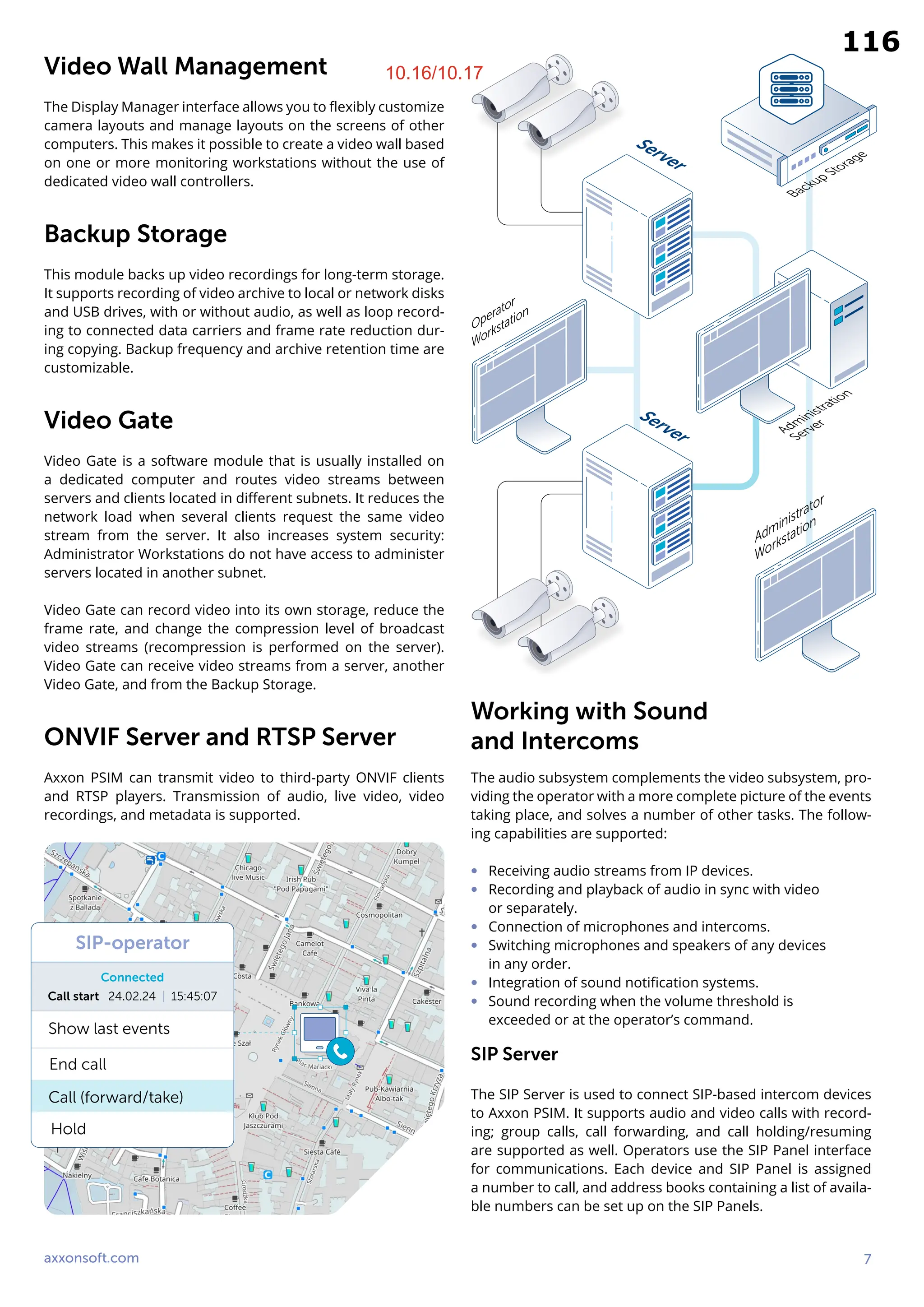
Video WallManagement
The Display Manager interface allows you to flexibly customize
camera layouts and manage layouts on the screens of other
computers. This makes it possible to create a video wall based
on one or more monitoring workstations without the use of
dedicated video wall controllers.
Backup Storage
This module backs up video recordings for long-term storage.
It supports recording of video archive to local or network disks
and USB drives, with or without audio, as well as loop record-
ing to connected data carriers and frame rate reduction dur-
ing copying. Backup frequency and archive retention time are
customizable.
Video Gate
Video Gate is a software module that is usually installed on
a dedicated computer and routes video streams between
servers and clients located in different subnets. It reduces the
network load when several clients request the same video
stream from the server. It also increases system security:
Administrator Workstations do not have access to administer
servers located in another subnet.
Video Gate can record video into its own storage, reduce the
frame rate, and change the compression level of broadcast
video streams (recompression is performed on the server).
Video Gate can receive video streams from a server, another
Video Gate, and from the Backup Storage.
ONVIF Server and RTSP Server
Axxon PSIM can transmit video to third-party ONVIF clients
and RTSP players. Transmission of audio, live video, video
recordings, and metadata is supported.
Working with Sound
and Intercoms
The audio subsystem complements the video subsystem, pro-
viding the operator with a more complete picture of the events
taking place, and solves a number of other tasks. The follow-
ing capabilities are supported:
∞ Receiving audio streams from IP devices.
∞ Recording and playback of audio in sync with video
or separately.
∞ Connection of microphones and intercoms.
∞ Switching microphones and speakers of any devices
in any order.
∞ Integration of sound notification systems.
∞ Sound recording when the volume threshold is
exceeded or at the operator’s command.
SIP Server
The SIP Server is used to connect SIP-based intercom devices
to Axxon PSIM. It supports audio and video calls with record-
ing; group calls, call forwarding, and call holding/resuming
are supported as well. Operators use the SIP Panel interface
for communications. Each device and SIP Panel is assigned
a number to call, and address books containing a list of availa-
ble numbers can be set up on the SIP Panels.
Operator
Workstation
Administrator
Workstation
Server
Server
Backup Storage
Administration
Server
SIP-operator
Connected
Show last events
Call start 24.02.24 | 15:45:07
End call
Call (forward/take)
Hold
10.16/10.17
116
9.
8 Physical SecurityIntegration Platform
ACFA PSIM
ACFA PSIM is a subsystem for managing access control
systems, fire and intruder alarms, and perimeter protection
systems. It includes integration and service modules,
dedicated user interfaces and supports dozens
of physical security systems.
Access Control, Time and
Attendance
ACFA PSIM provides interfaces for managing all integrated ac-
cess control systems, including creating employees (cardhold-
ers) and departments, customizing time zones and access lev-
els. It supports passport scanning and access card issuance,
as well as user identification at the entrance by card and video
image based on comparing the face captured by the video
camera with the cardholder’s photo from the database, which
is performed using the Event Manager window.
The Time and Attendance module helps monitor work disci-
pline. It allows flexible configuration of work schedules, taking
into account days off, holidays, justification documents, and
overtime; it also generates reports.
In total, more than 20 types of access control and time and at-
tendance reports are available, which can be centrally obtained
via the web interface, printed, and exported in various formats.
Equipment Operation
The Interactive Map and Event Viewer interfaces are used to
display and control the status of devices. According to speci-
fied permissions, operators can monitor events from devices,
view video from linked cameras, configure and manage equip-
ment, including arming/disarming alarm groups, controlling
actuators, etc. For a number of systems, auto-configuration is
available, which involves reading the equipment configuration
and automatic creation of the object tree in Axxon PSIM.
Multi-Factor Identification and
Vehicle Access Control
ACFA PSIM supports long-range identification readers for or-
ganizing vehicle access, breathalyzers, biometric readers for
fingerprint recognition, palm vein scanning, and iris identifi-
cation. It also supports devices for body temperature meas-
urement and mask-wearing control, as well as cameras with
built-in license plate recognition.
Any identifier can be used for access organization. In case
of multi-factor identification, access is granted based on two
or more identifiers: access card + biometric attribute, access
card + license plate, biometric attribute + PIN, access card +
biometric attribute + PIN, etc. Breathalyzer testing can also be
used in the multi-factor access scenario.
Arrival–leaving Report
Period: 08.02.2024
Full name, position
Luciano Hessel
Tech Writer
09:12:55 18:45:15
08:59:03 21:31:08
09:05:48 17:59:23
09:00:21 18:02:43
Arrival Leaving
Linwood Conatser
Tech Consulting
Courtney Pestone
Product Manager
Tommie Kastner
Support Engineer
PDF 100%
10.1
11.5
117
10.
axxonsoft.com 9
Event Manageris an
interface for requesting
operator action, such as
confirming or denying
access. The appearance
of the window and the
information that the
operator will receive at
the request can be flexibly
customized for each type
of event, which makes this
interface a convenient
versatile tool for managing
the security system.
Low-level integration with
a range of systems allows
for direct interaction with
devices without the need
for vendor software.
10.15
10.13
118
11.
10 Physical SecurityIntegration Platform
POS PSIM
POS PSIM is a solution for retail that combines video monitoring of cash register operations, re-
tail video analytics, and web reports. It helps detect fraud and compliance violations and is used
by security departments and commercial units of retail enterprises. Support for QR/barcode
reading enables POS PSIM to track items in manufacturing and logistics applications.
POS Supervision
POS PSIM’s cashier operations supervision capability is based
on synchronizing the cash register information with video se-
quences captured by a camera pointed at the cash register.
As a result, watching real-time video or recorded footage, the
operator sees the picture of the customer’s checkout accom-
panied by captions. The captions include the receipt text and
cash register operations that are not indicated on the receipt,
such as cash drawer opening or manual product code input.
This gives the operator the full picture of what is happening
at the cash operation unit, helping detect common fraud inci-
dents, cashier errors, violations and facilitating faster resolu-
tion of disputed situations with customers.
Cashier: Cliff Marcano Receipt: 2553
Data
29 Feb 2024
17:08:20
Sub total: 132.6 USD
29 Feb 2024
17:08:24
46078310244520
Men's Dress Shirt Regular Fit Solid
69.51 USD*1 = 69.51 USD
54490000021854
DSP Men's High Polo — Short Sleeve
55.8 USD*1 = 55.8 USD
29 Feb 2024
17:08:29
46700000560024
Hanes Men's Double Tough Ankle Socks
7.29 USD*1 = 7.29 USD
29 Feb 2024
17:08:31
Date/time
PDF 100%
119
12.
axxonsoft.com 11
Retail VideoAnalytics
Video detectors determine the number of people in queues
and count visitors to the store or a selected area of the sales
floor. The data can be obtained in real time or in reports.
This makes it possible to quickly take necessary measures,
such as opening an additional cash register, and optimize the
work schedule of staff, as well as analyze the efficiency of
store operations.
The Heat Map tool creates a graphical representation of move-
ment in the camera’s field of view, such as foot traffic: it shows
the areas where people prefer to stay and the less frequented
areas in different colors. The data collected can also be dis-
played in the form of a graph or table. The Heat Map enables
you to draw conclusions about the attractiveness of different
areas of the retail space, such as promo stands, showcases,
shelves, product placement areas, etc. It also helps identify
bottlenecks and efficiently manage staff allocation.
POS Reports
The Web Report System provides access to centralized statis-
tics of the cashier operations supervision from any store of the
retail chain. It can be used as part of an integrated monitoring
center and individually to provide remote access to required
statistics for managers, security department heads, and retail
chain top management. The system allows for viewing reports
on cashier operations, including related footage and the re-
ceipts, as well as printing the reports out or emailing them.
The report by potential violations allows you to quickly view
sequences of events that may correspond to cashier errors
and fraud. These include, for example, canceling all items in
a receipt and then adding items to the same receipt, voiding
a receipt, double scanning, and reloading the cash register.
POS PSIM supports simple
text search of recorded
transactions by captions
and complex search
queries, such as search by
total amount of a receipt
in a specified range,
receipts with canceled
items, search by number
of items in a receipt,
search by weight
and cost of goods,
and many others.
09:00
200
300
400
500
12:00 15:00 18:00 21:00
Visitor
number
Time
Visitor Count Report
10.5
10.16/10.17
10.16/10.17
120
13.
12 Physical SecurityIntegration Platform
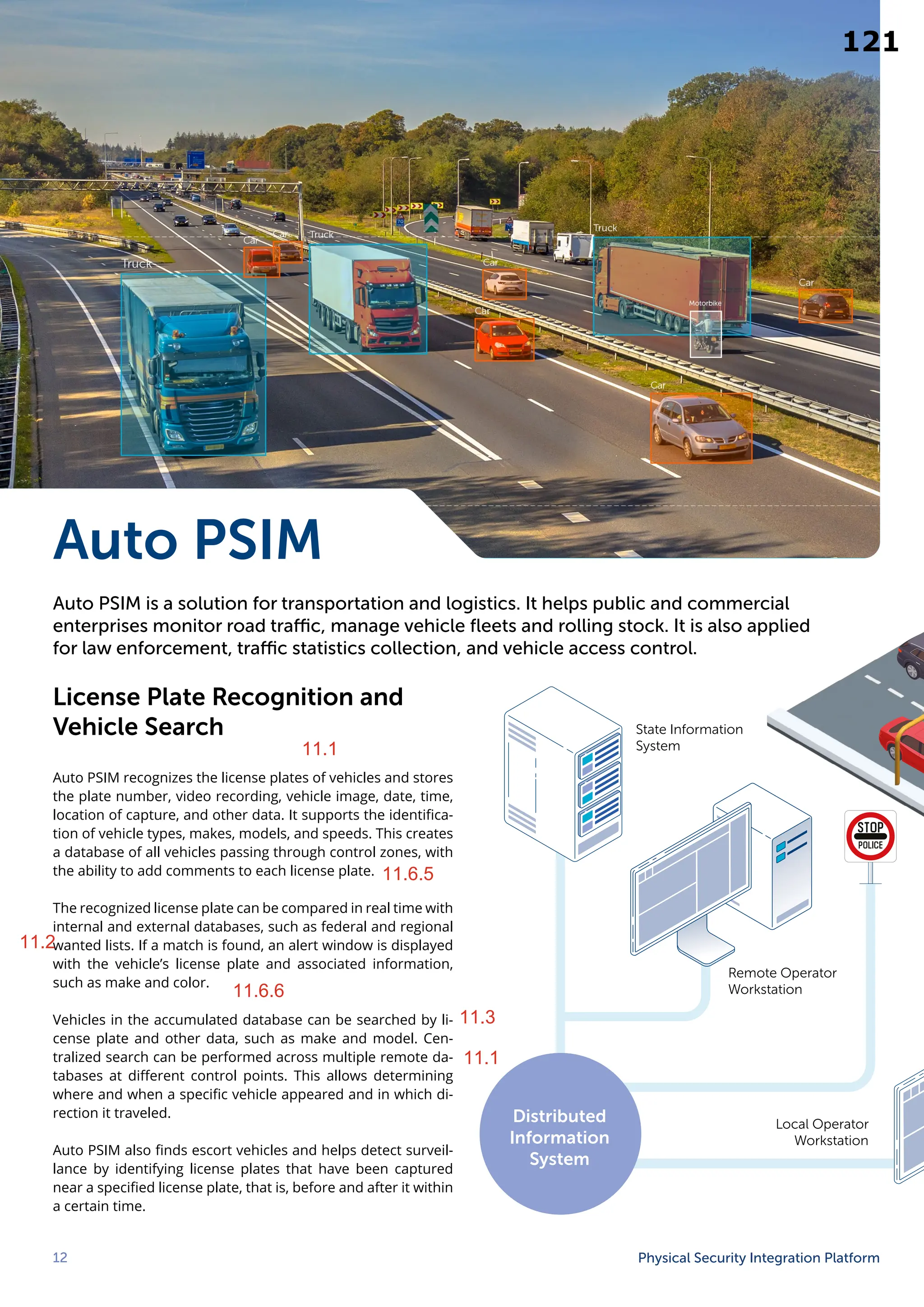
Auto PSIM
Auto PSIM is a solution for transportation and logistics. It helps public and commercial
enterprises monitor road traffic, manage vehicle fleets and rolling stock. It is also applied
for law enforcement, traffic statistics collection, and vehicle access control.
License Plate Recognition and
Vehicle Search
Auto PSIM recognizes the license plates of vehicles and stores
the plate number, video recording, vehicle image, date, time,
location of capture, and other data. It supports the identifica-
tion of vehicle types, makes, models, and speeds. This creates
a database of all vehicles passing through control zones, with
the ability to add comments to each license plate.
The recognized license plate can be compared in real time with
internal and external databases, such as federal and regional
wanted lists. If a match is found, an alert window is displayed
with the vehicle’s license plate and associated information,
such as make and color.
Vehicles in the accumulated database can be searched by li-
cense plate and other data, such as make and model. Cen-
tralized search can be performed across multiple remote da-
tabases at different control points. This allows determining
where and when a specific vehicle appeared and in which di-
rection it traveled.
Auto PSIM also finds escort vehicles and helps detect surveil-
lance by identifying license plates that have been captured
near a specified license plate, that is, before and after it within
a certain time.
Remote Operator
Workstation
Local Operator
Workstation
State Information
System
Distributed
Information
System
11.6.5
11.6.6
11.2
11.3
11.1
11.1
121
11.1
11.6.5
11.2
11.6.6
11.3
11.1
14.
axxonsoft.com 13
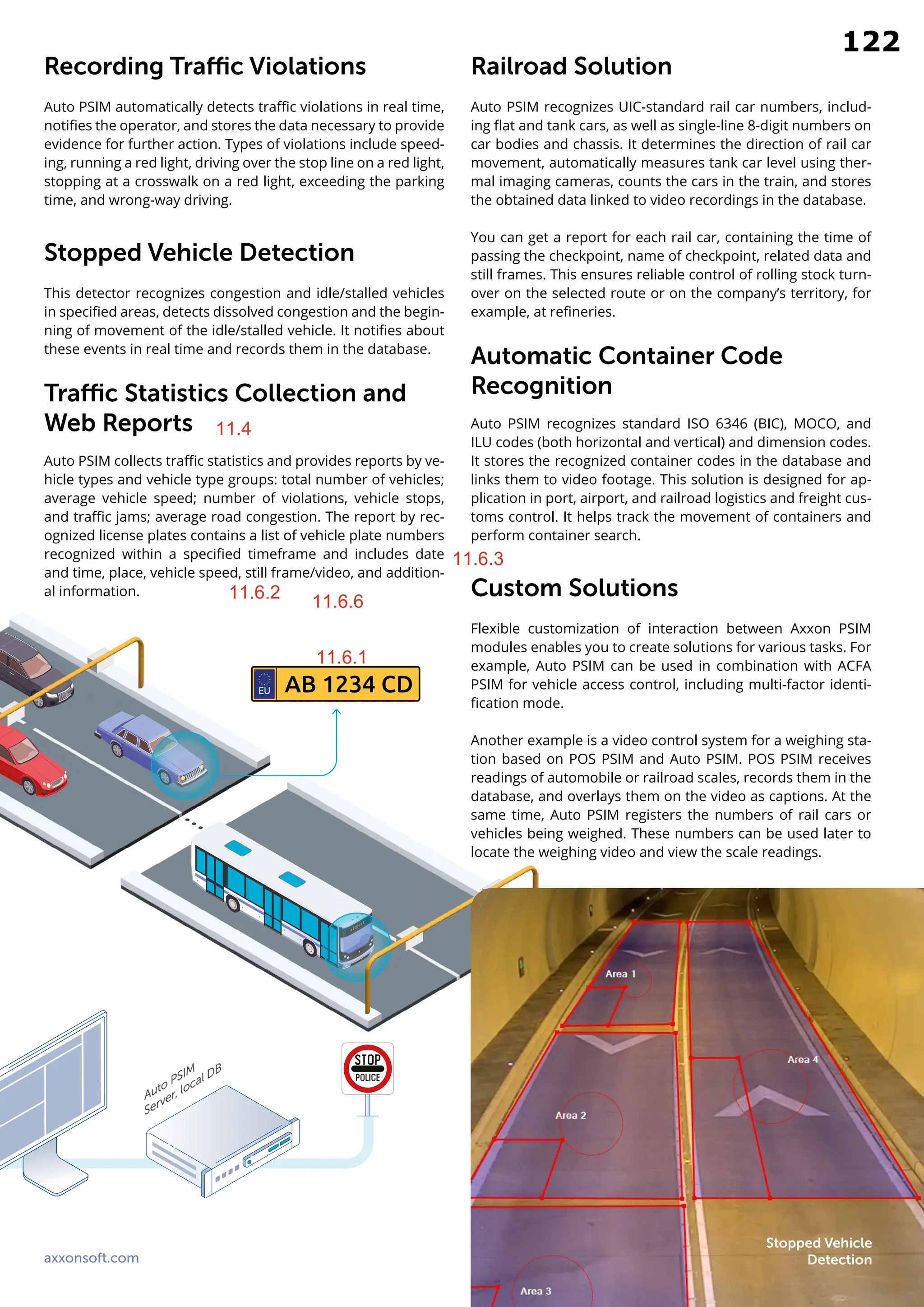
Recording TrafficViolations
Auto PSIM automatically detects traffic violations in real time,
notifies the operator, and stores the data necessary to provide
evidence for further action. Types of violations include speed-
ing, running a red light, driving over the stop line on a red light,
stopping at a crosswalk on a red light, exceeding the parking
time, and wrong-way driving.
Stopped Vehicle Detection
This detector recognizes congestion and idle/stalled vehicles
in specified areas, detects dissolved congestion and the begin-
ning of movement of the idle/stalled vehicle. It notifies about
these events in real time and records them in the database.
Traffic Statistics Collection and
Web Reports
Auto PSIM collects traffic statistics and provides reports by ve-
hicle types and vehicle type groups: total number of vehicles;
average vehicle speed; number of violations, vehicle stops,
and traffic jams; average road congestion. The report by rec-
ognized license plates contains a list of vehicle plate numbers
recognized within a specified timeframe and includes date
and time, place, vehicle speed, still frame/video, and addition-
al information.
Railroad Solution
Auto PSIM recognizes UIC-standard rail car numbers, includ-
ing flat and tank cars, as well as single-line 8-digit numbers on
car bodies and chassis. It determines the direction of rail car
movement, automatically measures tank car level using ther-
mal imaging cameras, counts the cars in the train, and stores
the obtained data linked to video recordings in the database.
You can get a report for each rail car, containing the time of
passing the checkpoint, name of checkpoint, related data and
still frames. This ensures reliable control of rolling stock turn-
over on the selected route or on the company’s territory, for
example, at refineries.
Automatic Container Code
Recognition
Auto PSIM recognizes standard ISO 6346 (BIC), MOCO, and
ILU codes (both horizontal and vertical) and dimension codes.
It stores the recognized container codes in the database and
links them to video footage. This solution is designed for ap-
plication in port, airport, and railroad logistics and freight cus-
toms control. It helps track the movement of containers and
perform container search.
Custom Solutions
Flexible customization of interaction between Axxon PSIM
modules enables you to create solutions for various tasks. For
example, Auto PSIM can be used in combination with ACFA
PSIM for vehicle access control, including multi-factor identi-
fication mode.
Another example is a video control system for a weighing sta-
tion based on POS PSIM and Auto PSIM. POS PSIM receives
readings of automobile or railroad scales, records them in the
database, and overlays them on the video as captions. At the
same time, Auto PSIM registers the numbers of rail cars or
vehicles being weighed. These numbers can be used later to
locate the weighing video and view the scale readings.
AB 1234 CD
EU
Stopped Vehicle
Detection
11.4
11.6.1
11.6.2
11.6.3
11.6.6
122
11.4
11.6.1
11.6.2 11.6.6
11.6.3
15.
14 Physical SecurityIntegration Platform
Comprehensive Security
System Monitoring Module
The Comprehensive Monitoring
Module significantly improves
reliability and efficiency of
distributed systems and
reduces the number of
false calls of service and
security companies.
This module is designed for centralized monitoring of large distributed
systems. It processes alarm messages from remote protected sites and
monitors the technical condition of the equipment. The module can
utilize low bandwidth communication channels.
Equipment and Software Health
Monitoring
The Comprehensive Monitoring Module receives, records,
and displays information on the status of distributed security
system components: operability of video cameras, video sub-
system software and hard disks; availability of communication
channel; size of video storage; operability of access control
and alarm systems; technical parameters of servers; signals
from uninterruptible power supplies. Real-time monitoring
helps quickly eliminate malfunctions and maintain a high level
of security at all protected sites.
Monitoring Distributed Sites
The Monitoring Module receives and records alarm messages
from local systems installed at distributed sites. The opera-
tor receives a notification and can view detailed information
about the alarm, including associated video recordings or still
frames. The time of alarm reception is logged, enabling the
monitoring of operator performance.
Operators have access to real-time video feeds from the cam-
eras and can request video recordings from the storage of re-
mote servers. They can also remotely control alarms, access
control systems, and executive devices. This includes actions
such as activating a siren, locking a door, arming or disarming
the site, and more.
Decoding
Communication
channel
Hardware
Videosystem
software
Size of archives
Cameras
ACS
SFA
Detections
Temperature
in warning area
Temperature
in alarm area
Temperature
sensors
123
16.
axxonsoft.com 15
Unique UserInterface
The user interface of the Comprehensive Monitoring Module
makes it possible to control an integrated security system of
any scale with a minimum number of workstations. Protected
sites are displayed in the form of blocks with icons, in which
all alarms and equipment statuses are organized into groups.
Sites can be grouped by affiliation (territorial, administrative,
departmental) for centralized monitoring of multiple distribut-
ed locations, such as bank branches, retail chain stores, or gas
stations in different cities.
Individual events can be configured for each site, which will
be displayed in the interface in the way familiar to the oper-
ator. Distinguishing operator access rights to groups of sites
protects against unauthorized interference in the operation of
certain segments of the security system.
The failure of even one
component of the security
system means vulnerability.
Therefore, monitoring
the health of equipment
is instrumental for any
system, especially a large
and distributed one.
Interaction with Auto PSIM
The system based on the Monitoring Module and Auto PSIM is
used at gas stations and other sites that do not have a broad-
band connection with the monitoring center. It addresses
remote control tasks, including those related to the use of a
unified license plate number database:
∞ Matching a plate number recognized at a site with
the centralized or local database.
∞ Notification of the operator in the monitoring center
and/or at a site in case of a match.
∞ Centralized viewing of information on license plates
recognized at the sites.
∞ Generating site-related reports: average vehicle
dwell time, number of vehicles during a specified time,
license plate list.
Reports
The reporting system generates general and detailed reports
on equipment failures, alarm situations, operator actions, video
and photo reports, and statistical reports on alarms and equip-
ment malfunctions. Analyzing these reports enables you to:
∞ Obtain information about the impact of various types
of faults on the overall system performance.
∞ Identify recurring issues in the equipment operation
and prevent its failure by replacing components with
more reliable ones.
∞ Strengthen the security of sites where alarm situations
are more frequent.
Type text here
10.16/10.17
Dashboard
124
4. If necessary,do the following operations with the report, then quit the report preview program by
clicking the File -> Exit viewer in the main menu, or by clicking the button in the top right corner.
The available operations for the report are listed in the table below.
Operation
Operation invocation
Main menu item
Context
menu item
Toolbar
button
Open the report, saved in .rsd or .xml File -> Open -
Save the report in .rsd or .xml File -> Save -
Export the report to one of the common formats File -> Export -
Print the report File -> Print -
Activate the «Hand» tool View -> Scrolling Scrolling
Zoom in the report pages View -> Zoom in Zoom in
Zoom out the report pages View -> Zoom out Zoom out
Enable dynamic scaling of report pages
View -> Dynamic
scaling
Dynamic
scaling
Zoom in the selected area of the report
View -> Region
scaling
Region
scaling
Scale in page size
View -> In page
size
In page size
Scale in page width
View -> In page's
width size
In page's
width size
11.5
126
11.5
19.
You can alsoexport the report to a file of the specified format. To export the report, click the button. A standard dialog box for
saving the file will open. The following export file formats are available: pdf, rtf, htm, xls, csv, gif, jpg, bmp, emf, tif, png.
Note
The standard dialog box (Windows OS) isn't a part of It is a Windows system dialog box.
Print Axxon PSIM.
Note
All further operations with the exported report file are performed in the associated applications and do not depend on Axxon
.
PSIM
287
11.5
127
11.5
L2+/Lite L3 GigabitEthernet Access /
Aggregation Switch with 4 10G Uplinks
ECS4120 Series
The Edgecore ECS4120 switch series is a Gigabit Ethernet access switch with four 10G uplink ports. The switch is ideal for Internet Service
Providers (ISPs) and Multiple System Operators (MSOs) to provide home users with triple-play services with up to Gigabit bandwidth. It is
also an ideal Gigabit access switch for SMB, enterprise, and campus networks. The ECS4120 switch series is packed with features that
bring high availability, comprehensive security, robust multicast control, and advance QoS to the network edge, while maintaining simple
management. The switch also supports the most advance IPv6 management, IPv6 security, and IPv6 multicast control in accordance with
the growth of IPv6 deployment. ISPs can expand their services from home to business users by providing a more reliable and resilient
network (ITU-T G.8032 ERPS), L2 VPNs, and advanced OAM (Operations, Administration, and Maintenance) functions to ensure
service-level agreements.
Datasheet L2 Switch
Performance and Scalability
The Edgecore ECS4120 Series is a high-performance Gigabit
Ethernet L2+/L3 Lite managed switch with 128Gbps/176Gbps
switching capacity. The switch delivers wire-speed switching
performance on all Gigabit ports, taking full advantage of
existing high-performance Gigabit CPEs, PCs,11n/ac Wi-Fi APs
etc, significantly improving the responsiveness of applications
and file transfer times.
The four built-in 10G SFP+ ports provide uplink flexibility,
allowing the insertion of fiber or copper, Gigabit or 10G
transceivers, to create up to 10 Gbps high-speed uplinks to
servers or service provider, corporate, or campus networks,
reducing bottlenecks and increasing the performance of the
access network.
The Voice VLAN function automatically detects VoIP devices by
OUI or LLDP and groups the voice traffic into a separate VLAN for
better performance. It can also automatically change port
priorities, so a higher CoS value can be assigned for guaranteed
voice quality.
Continuous Availability
The IEEE 802.1w Rapid Spanning Tree Protocol provides a
loop-free network and redundant links to the core network with
rapid convergence, to ensure faster recovery from failed links,
enhancing overall network stability and reliability.
The IEEE 802.1s Multiple Spanning Tree Protocol runs STP per
VLAN base, providing Layer 2 load sharing on redundant links up
to 64 instances.
The ECS4120 Series supports IEEE 802.3ad Link Aggregation
Control Protocol (LACP). LACP increases bandwidth by
automatically aggregating several physical links together as a
logical trunk and offers load balancing and fault tolerance for
uplink connections.
Continuous Availability-countinued
The ECS4120 Series supports G.8032 Ethernet Ring Protection
Switching with the ability for the network to detect and recover
from incidents without impacting users, meeting the most
demanding quality and availability requirements. Rapid
recovery time when problems do occur is as low as 50ms.
Reliability and Energy Efficiency
The fanless design of ECS4120-28T ensures noiseless
operation and increases the reliability of the system.
The design of the ECS4120 Series incorporates high energy
efficiency in order to reduce the impact on the environment. The
Green Ethernet power-saving features and fanless design
significantly reduce the power consumption.
Enhanced Security
Port security limits the total number of devices from using a
switch port and protects against MAC flooding attacks.
IEEE 802.1X port-based or MAC-based access control ensures
all users are authorized before being granted access to the
network. When a user is authenticated, the VLAN, QoS and
security policy are automatically applied to the port where the
user is connected, otherwise the port is grouped in a guest
VLAN with limited access.
DHCP snooping allows a switch to protect a network from rogue
DHCP servers that offer invalid IP addresses.
IP Source Guard prevents people from using IP addresses that
were not assigned to them.
Access Control Lists (ACLs) can be used to restrict access to
sensitive network resources by denying packets based on
source and destination MAC addresses, IP addresses, or
TCP/UDP ports. ACLs are hardware supported, so switching
performance is not compromised.
Key Features and Benefits
130
12
12.1
23.
Datasheet L2 Switch
Stacking
ECS4120-28Fv2-I_EUS(Only Hardware Version R01A) supports
hardware stacking via 10G SFP+ port with Edgecore DAC cable
(ET5402-DAC-1M) , no special stacking module and stacking cable are
needed, up to 4 switches can be stacked together. The switch stack
can be managed with a single IP address as a single entity, one switch
will become master and all other switches within the stack will
become slave, the configuration and firmware can be automatically
synchronized from master to slave for easy management. When 4
switches are stacked in a ring topology, if there is link failure on the
stacking cable, traffic will go through the redundant link so there is no
network downtime. The hardware stacking supports cross stack
trunking, for example, 10G ports on different switches can be trunked
together, if one unit fail, there is still redundant port on the switch for
uplink.
Superior Management
An industry-standard command-line interface (CLI), accessed through
the console port or Telnet, provides a familiar user interface and
command set for users to manage the switch.
An embedded user-friendly web interface helps users to quickly and
simply configure switches.
The ECS4120 Series supports SNMPv1,2c,3 and four-group RMON.
The switch provides a complete private MIB for the configuration of
most functions via the SNMP protocol.
Administrators can backup and restore firmware and configuration
files via TFTP or FTP. The switch also provides the configuration of
auto-provision for ease of use in large deployments.
AAA (Authentication, Authorization and Accounting) via RADIUS,
TACACS+, enables centralized control of the switch. You can also
authorize access rights per user and account for all actions performed
by administrators.
Service Monitoring and Management
The ECS4120 Series supports IEEE 802.1ag and ITU-T Y.1731,
allowing service providers to monitor end-to-end services, identify
connectivity and performance issues, and isolate problems from a
remote location without dispatching an engineer onsite.
The switch also provides the capability to monitor service availability,
delay and delay variation for verifying SLA conformance (for billing
purposes) and providing advance indication of performance
degradation before a service outage occurs.
Virtual Private Networks
The ECS4120 Series supports Layer 2 VPNs by using Q-in-Q functions,
where an 802.1Q tag from a customer VLAN (called CE-VLAN ID) is
encapsulated in a second 802.1Q tag from a service-provider network
(called an SP-VLAN ID). The switch supports rewriting the VLAN tag
of egress traffic when the ingress traffic is tagged.
The switch also supports Layer 2 Protocol Tunneling for STP, CDP,
VTP, PVST+, with Cisco-proprietary multicast address
(01-00-0c-cd-cd-d0) replacement.
Private VLANs (traffic segmentation per port) isolate edge ports to
ensure user privacy.
DAI (Dynamic ARP Inspection) is a security feature that validates
Address Resolution Protocol (ARP) packets in a network. DAI allows a
network administrator to intercept, log, and discard ARP packets with
invalid MAC-to-IP address bindings.
Secure Shell (SSH) and Secure Sockets Layer (SSL/HTTPS) encrypt
Telnet and web access to the switch, providing secure network
management.
The ECS4120 Series also supports both RADIUS and TACACS+
authentication methods to secure your network.
Comprehensive QoS
The ECS4120 Series offers advanced QoS for marking, classification,
and scheduling to deliver best-in-class performance for data, voice,
and video traffic at wire speed. Eight egress queues per port enable
differentiated management of up to eight traffic types through the
switch.
Traffic is prioritized according to 802.1p and DSCP to provide optimal
performance for real-time applications. Weighted Round Robin (WRR)
and strict priority ensure differential prioritization of packet flows and
avoid congestion of ingress and egress queues.
Asymmetric bidirectional rate-limiting, per port or per traffic class,
preserves network bandwidth and allows maximum control of
network resources.
The ECS4120 Series supports Three Color Marker and Policing Single
rate: Committed Information Rate (CIR) Two rate: CIR + Peak
Information Rate (PIR) Traffic Policing: The switch drops or remarks
the priority tags of packets when they exceed the burst size.
Robust Multicast Control
IGMP snooping prevents the flooding of multicast traffic by
dynamically configuring switch ports so that multicast traffic is
forwarded to only those ports associated with an IP multicast
receiver. IGMP increases the performance of networks by reducing
multicast traffic flooding.
IGMP groups allow you to create customer packages for IP-TV
channels, making switch configuration easy. IGMP Filtering prevents
subscribers seeing unsubscribed IP-TV channels. And, IGMP Throttling
allows you to set how many IP-TV channels a subscriber can receive
simultaneously.
Multicast VLANs are shared in the network, while subscribers remain
in separate VLANs. This increases network security and saves
bandwidth on core links. Multicast streams do not have to be routed in
core L3 switches, which saves CPU power.
Multicast VLAN Registration (MVR) is designed for applications such
as Media-on-Demand that send multicast traffic across an Ethernet
network.
IPv6 Support
The switch supports a number of IPv6 features, including IPv6
Management, DHCPv6 Snooping with Option 37, IPv6 Source Guide,
and MVR6.
131
24.
Datasheet L2 Switch
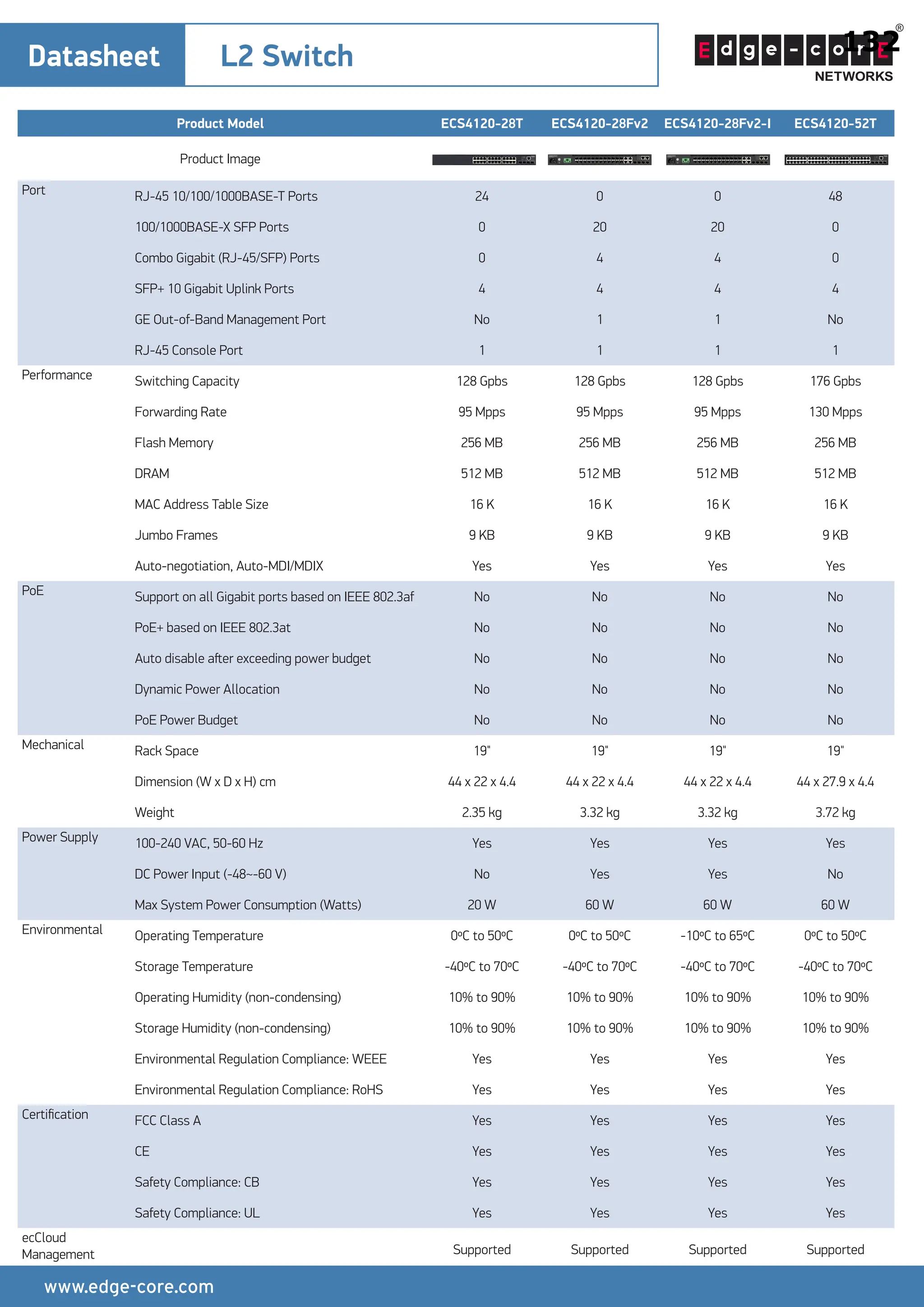
ProductModel ECS4120-28T ECS4120-28Fv2 ECS4120-28Fv2-I ECS4120-52T
Product Image
Port RJ-45 10/100/1000BASE-T Ports 24 0 0 48
100/1000BASE-X SFP Ports 0 20 20 0
Combo Gigabit (RJ-45/SFP) Ports 0 4 4 0
SFP+ 10 Gigabit Uplink Ports 4 4 4 4
GE Out-of-Band Management Port No 1 1 No
RJ-45 Console Port 1 1 1 1
Performance Switching Capacity 128 Gpbs 128 Gpbs 128 Gpbs 176 Gpbs
Forwarding Rate 95 Mpps 95 Mpps 95 Mpps 130 Mpps
Flash Memory 256 MB 256 MB 256 MB 256 MB
DRAM 512 MB 512 MB 512 MB 512 MB
MAC Address Table Size 16 K 16 K 16 K 16 K
Jumbo Frames 9 KB 9 KB 9 KB 9 KB
Auto-negotiation, Auto-MDI/MDIX Yes Yes Yes Yes
PoE Support on all Gigabit ports based on IEEE 802.3af No No No No
PoE+ based on IEEE 802.3at No No No No
Auto disable aſter exceeding power budget No No No No
Dynamic Power Allocation No No No No
PoE Power Budget No No No No
Mechanical Rack Space 19" 19" 19" 19"
Dimension (W x D x H) cm 44 x 22 x 4.4 44 x 22 x 4.4 44 x 22 x 4.4 44 x 27.9 x 4.4
Weight 2.35 kg 3.32 kg 3.32 kg 3.72 kg
Power Supply 100-240 VAC, 50-60 Hz Yes Yes Yes Yes
DC Power Input (-48~-60 V) No Yes Yes No
Max System Power Consumption (Watts) 20 W 60 W 60 W 60 W
Environmental Operating Temperature 0ºC to 50ºC 0ºC to 50ºC -10ºC to 65ºC 0ºC to 50ºC
Storage Temperature -40ºC to 70ºC -40ºC to 70ºC -40ºC to 70ºC -40ºC to 70ºC
Operating Humidity (non-condensing) 10% to 90% 10% to 90% 10% to 90% 10% to 90%
Storage Humidity (non-condensing) 10% to 90% 10% to 90% 10% to 90% 10% to 90%
Environmental Regulation Compliance: WEEE Yes Yes Yes Yes
Environmental Regulation Compliance: RoHS Yes Yes Yes Yes
Certification FCC Class A Yes Yes Yes Yes
CE Yes Yes Yes Yes
Safety Compliance: CB Yes Yes Yes Yes
Safety Compliance: UL Yes Yes Yes Yes
ecCloud
Management Supported Supported Supported Supported
132
12
12.3
12.5
12.5
12.4
12.4
12.6
12.6
12.11
12.12
25.
Datasheet L2 Switch
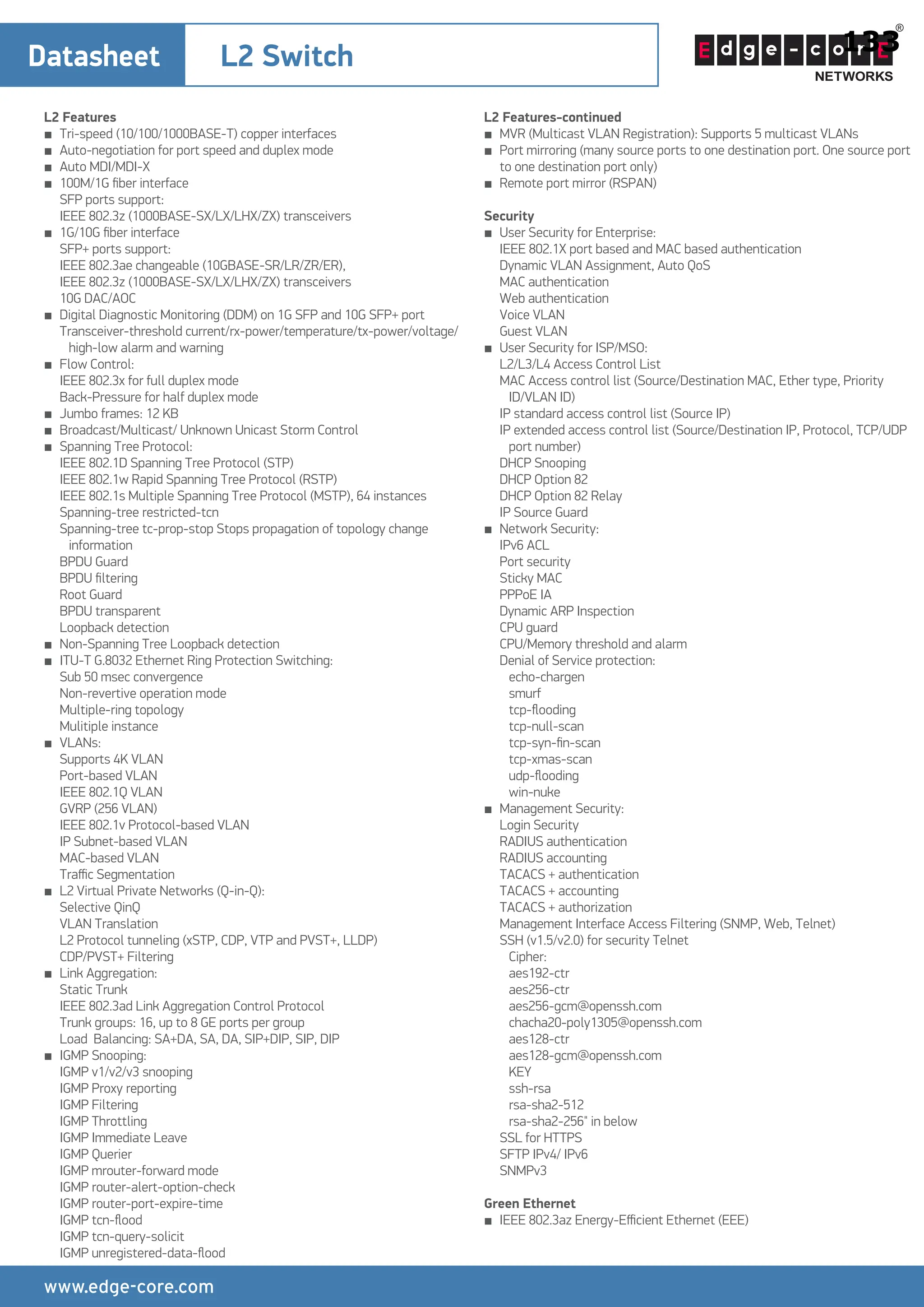
L2Features
■ Tri-speed (10/100/1000BASE-T) copper interfaces
■ Auto-negotiation for port speed and duplex mode
■ Auto MDI/MDI-X
■ 100M/1G fiber interface
SFP ports support:
IEEE 802.3z (1000BASE-SX/LX/LHX/ZX) transceivers
■ 1G/10G fiber interface
SFP+ ports support:
IEEE 802.3ae changeable (10GBASE-SR/LR/ZR/ER),
IEEE 802.3z (1000BASE-SX/LX/LHX/ZX) transceivers
10G DAC/AOC
■ Digital Diagnostic Monitoring (DDM) on 1G SFP and 10G SFP+ port
Transceiver-threshold current/rx-power/temperature/tx-power/voltage/
high-low alarm and warning
■ Flow Control:
IEEE 802.3x for full duplex mode
Back-Pressure for half duplex mode
■ Jumbo frames: 12 KB
■ Broadcast/Multicast/ Unknown Unicast Storm Control
■ Spanning Tree Protocol:
IEEE 802.1D Spanning Tree Protocol (STP)
IEEE 802.1w Rapid Spanning Tree Protocol (RSTP)
IEEE 802.1s Multiple Spanning Tree Protocol (MSTP), 64 instances
Spanning-tree restricted-tcn
Spanning-tree tc-prop-stop Stops propagation of topology change
information
BPDU Guard
BPDU filtering
Root Guard
BPDU transparent
Loopback detection
■ Non-Spanning Tree Loopback detection
■ ITU-T G.8032 Ethernet Ring Protection Switching:
Sub 50 msec convergence
Non-revertive operation mode
Multiple-ring topology
Mulitiple instance
■ VLANs:
Supports 4K VLAN
Port-based VLAN
IEEE 802.1Q VLAN
GVRP (256 VLAN)
IEEE 802.1v Protocol-based VLAN
IP Subnet-based VLAN
MAC-based VLAN
Traffic Segmentation
■ L2 Virtual Private Networks (Q-in-Q):
Selective QinQ
VLAN Translation
L2 Protocol tunneling (xSTP, CDP, VTP and PVST+, LLDP)
CDP/PVST+ Filtering
■ Link Aggregation:
Static Trunk
IEEE 802.3ad Link Aggregation Control Protocol
Trunk groups: 16, up to 8 GE ports per group
Load Balancing: SA+DA, SA, DA, SIP+DIP, SIP, DIP
■ IGMP Snooping:
IGMP v1/v2/v3 snooping
IGMP Proxy reporting
IGMP Filtering
IGMP Throttling
IGMP Immediate Leave
IGMP Querier
IGMP mrouter-forward mode
IGMP router-alert-option-check
IGMP router-port-expire-time
IGMP tcn-flood
IGMP tcn-query-solicit
IGMP unregistered-data-flood
L2 Features-continued
■ MVR (Multicast VLAN Registration): Supports 5 multicast VLANs
■ Port mirroring (many source ports to one destination port. One source port
to one destination port only)
■ Remote port mirror (RSPAN)
Security
■ User Security for Enterprise:
IEEE 802.1X port based and MAC based authentication
Dynamic VLAN Assignment, Auto QoS
MAC authentication
Web authentication
Voice VLAN
Guest VLAN
■ User Security for ISP/MSO:
L2/L3/L4 Access Control List
MAC Access control list (Source/Destination MAC, Ether type, Priority
ID/VLAN ID)
IP standard access control list (Source IP)
IP extended access control list (Source/Destination IP, Protocol, TCP/UDP
port number)
DHCP Snooping
DHCP Option 82
DHCP Option 82 Relay
IP Source Guard
■ Network Security:
IPv6 ACL
Port security
Sticky MAC
PPPoE IA
Dynamic ARP Inspection
CPU guard
CPU/Memory threshold and alarm
Denial of Service protection:
echo-chargen
smurf
tcp-flooding
tcp-null-scan
tcp-syn-fin-scan
tcp-xmas-scan
udp-flooding
win-nuke
■ Management Security:
Login Security
RADIUS authentication
RADIUS accounting
TACACS + authentication
TACACS + accounting
TACACS + authorization
Management Interface Access Filtering (SNMP, Web, Telnet)
SSH (v1.5/v2.0) for security Telnet
Cipher:
aes192-ctr
aes256-ctr
aes256-gcm@openssh.com
chacha20-poly1305@openssh.com
aes128-ctr
aes128-gcm@openssh.com
KEY
ssh-rsa
rsa-sha2-512
rsa-sha2-256" in below
SSL for HTTPS
SFTP IPv4/ IPv6
SNMPv3
Green Ethernet
■ IEEE 802.3az Energy-Efficient Ethernet (EEE)
133
11.2
11.2
11.2
11.8
11.9
12.2
12.8
12.2
12.2
12.9
12.10
12.2
26.
Datasheet L2 Switch
OAM
■IEEE 802.3ah Link
■ IEEE 802.1ag Connectivity Fault Management:
Connectivity check
Loopback
Linktrace
■ ITU-T Y.1731 Performance and Throughput Management:
Frame Delay
Frame Delay variation
QoS Features
■ Priority Queues: 8 hardware queues per port
■ Traffic classification:
IEEE 802.1p CoS
IP Precedence
DSCP
MAC Access control list ( Source/Destination MAC, Ether type, Priority ID/
VLAN ID)
IP Standard access control list (Source IP)
IP extended access control list (Source/Destination IP, Protocol, TCP/UDP
port number)
■ Traffic Scheduling:
Strict Priority
Weighted Round Robin
Strict + WRR
■ Ingress policy map (police rate, remark CoS)
■ Egress policy map (police rate, remark CoS/DSCP)
■ Rate Limiting (Ingress and Egress, per port base):
GE: Resolution 64Kbps ~ 1,000 Mbps
■ Auto Traffic Control
IPv6 Features
■ IPv4/IPv6 Dual Protocol stack
■ IPv6 Address Types Stack: Unicast
■ IPv6 Neighbor Discovery:
Duplicate address
Address resolution
Unreachable neighbor detection
■ Stateless auto-configuration
■ Manual configuration
■ Remote IPv6 ping
■ IPv6 Telnet support
■ HTTP over IPv6
■ SNMP over IPv6
■ IPv6 Syslog support
■ IPv6 TFTP support
■ IPv6 MLD filter: MLD max-groups (throttling)
■ IPv6 ND snooping
■ MLD Snooping v1/v2
■ IPv6 source guard
■ DHCPv6 snooping
■ MVR6
■ TACACS IPv6
Routing
■ IP interface IPv4/v6: 256/128 (Shared)
■ IPv4/IPv6 Static Route
■ Host route IPv4/v6: 4K/2K
■ Net route IPv4/v6: 512/128
■ DHCP Server
■ RIP v1/v2
Management
■ Switch Management:
CLI via console port or Telnet
Web management
SNMP v1, v2c, v3
■ IP clustering (32 members)
■ Firmware & Configuration:
Firmware upgrade via TFTP/HTTP/FTP server
Dual images
Multiple configuration files
Configuration file upload/download via TFTP/HTTP/FTP server
Firmware auto upgrade
■ RMON (groups 1, 2, 3 and 9)
■ BOOTP, DHCP client for IP address assignment
■ DHCP dynamic provision option 66,67
■ SNTP/NTP IPv4/ IPv6
■ DNS client
■ Event/Error Log
■ Syslog
■ SMTP
■ Support LLDP (802.1ab) IPv4/ IPv6
■ sFlow v4, v5
■ Cable diagnostics
■ Traceroute
■ Traceroute6
■ DHCP server (8 pools, 512 IP addaress)
■ TWAMP probe and responder
Safety
■ UL (CSA 22.2. NO 60950-1 & UL60950-1)
■ CB (IEC60950-1)
Electromagnetic Compatibility
■ CE Mark
■ FCC Class A
■ CISPR Class A
■ BSMI
Environmental Specifications
■ Temperature:
0ºC to 50ºC standard operation
-10ºC to 65ºC (ECS4120-28Fv2-I)
-40℃ to 70℃ (Non-Operating)
■ Humidity: 10% to 90% (Non-condensing)
Reliability: MTBF up to 290,000 hrs
Power Supply
■ Power input
AC Power input: 100 to 240 VAC, 50/60 Hz, 1.0A
DC power input: -48 ~ -60 VAC, 3.0 A
Dying Gasp (ECS4120-28Fv2 and ECS4120-28Fv2-I only)
■
134
11.2
11.2
11.7
11.10
11.10
11.10
11.10
12.2
12.2
12.7
12.10
12.10
12.10
12.13
12.10
12.10
12.10
12.1
Incredible
Immersion with
Ultra-Narrow Bezel
TheVL5F series provides all-encompassing screen
immersion thanks to its ultra-narrow 3.5 mm
bezel-to-bezel, while its outstanding IPS panel
delivers a clear image from any angle. With its
extremely attractive and highly functional design, it
can be used to deliver advertising and information
in a variety of business environments.
VL5F Series
137
30.
Incredible Immersion withUltra-Narrow Bezel
VL5F Series
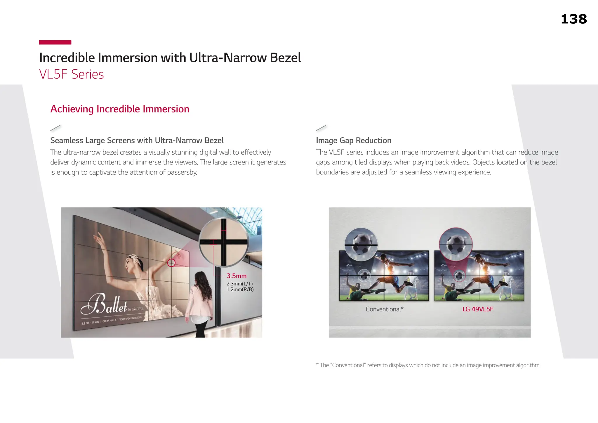
Seamless Large Screens with Ultra-Narrow Bezel
Achieving Incredible Immersion
The ultra-narrow bezel creates a visually stunning digital wall to effectively
deliver dynamic content and immerse the viewers. The large screen it generates
is enough to captivate the attention of passersby.
Image Gap Reduction
The VL5F series includes an image improvement algorithm that can reduce image
gaps among tiled displays when playing back videos. Objects located on the bezel
boundaries are adjusted for a seamless viewing experience.
Conventional* LG 49VL5F
3.5mm
2.3mm(L/T)
1.2mm(R/B)
* The "Conventional" refers to displays which do not include an image improvement algorithm.
138
31.
Incredible Immersion withUltra-Narrow Bezel
VL5F Series
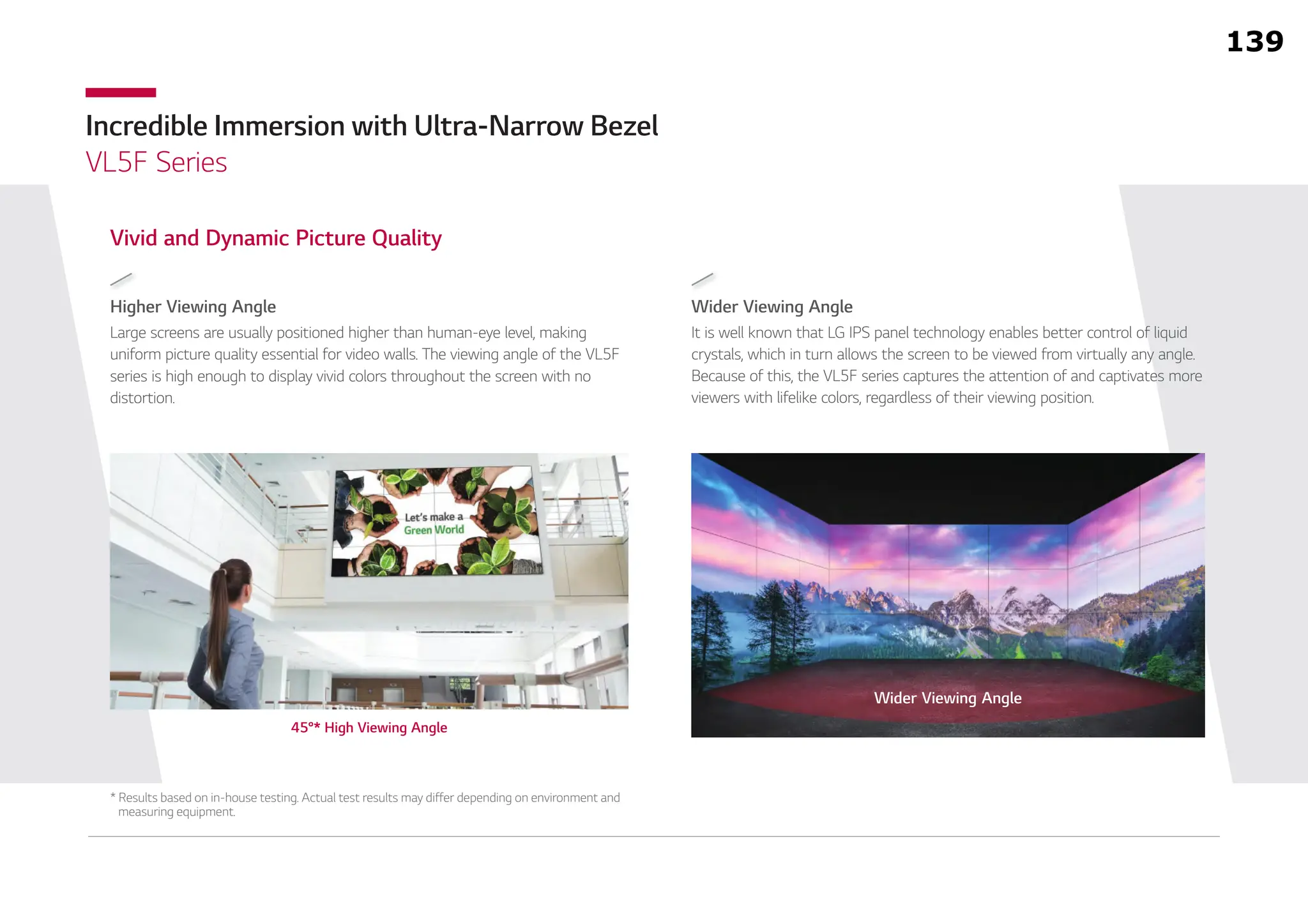
Wider Viewing Angle
It is well known that LG IPS panel technology enables better control of liquid
crystals, which in turn allows the screen to be viewed from virtually any angle.
Because of this, the VL5F series captures the attention of and captivates more
viewers with lifelike colors, regardless of their viewing position.
Higher Viewing Angle
Vivid and Dynamic Picture Quality
Large screens are usually positioned higher than human-eye level, making
uniform picture quality essential for video walls. The viewing angle of the VL5F
series is high enough to display vivid colors throughout the screen with no
distortion.
* Results based on in-house testing. Actual test results may differ depending on environment and
measuring equipment.
Wider Viewing Angle
45°* High Viewing Angle
139
32.
Incredible Immersion withUltra-Narrow Bezel
VL5F Series
Simple White Balance Adjustment
In conventional video walls, white balance was adjustable only in “full-white” mode,
but the VL5F series allows you to modify each value of grey scale to achieve more
detailed and precise white balance adjustment.
Easy Color Adjustment
Depending on the content, the color temperature of the display can be easily
adjusted in increments of 100K using a remote control.
User Convenience
13,000K
3,200K
140
33.
Incredible Immersion withUltra-Narrow Bezel
VL5F Series
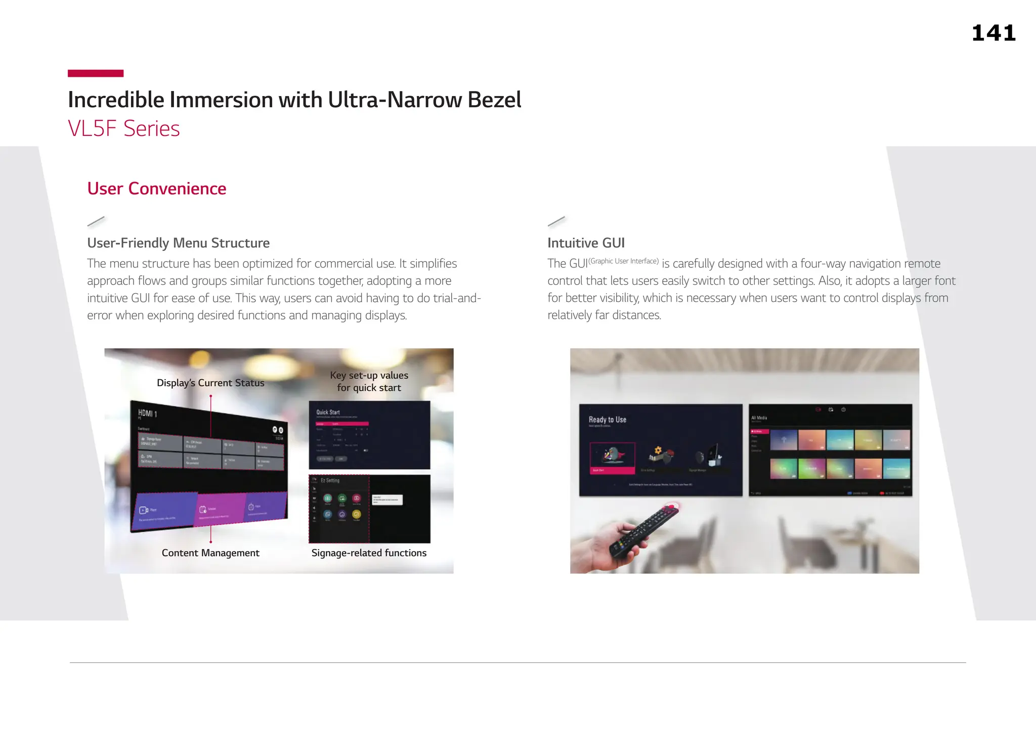
Intuitive GUI
The GUI(Graphic User Interface)
is carefully designed with a four-way navigation remote
control that lets users easily switch to other settings. Also, it adopts a larger font
for better visibility, which is necessary when users want to control displays from
relatively far distances.
User-Friendly Menu Structure
The menu structure has been optimized for commercial use. It simplifies
approach flows and groups similar functions together, adopting a more
intuitive GUI for ease of use. This way, users can avoid having to do trial-and-
error when exploring desired functions and managing displays.
User Convenience
Display’s Current Status
Key set-up values
for quick start
Content Management Signage-related functions
141
NEXIS VW8/VW9 Seriesเป็น Video Controller ที่ใช้สถาปัตยกรรมฮาร์ดแวร์FPGA
ออกแบบมาให้ติดตั้ง I/O Board แบบโมดูลาร์ เข้ากับ Main Unit เลือกอินเทอร์เฟซ I/O
ได้ตามต้องการ ถอด-เสียบการ์ดได้ทันทีโดยไม่ต้องปิดเครื่อง จัดการแหล่งสัญญาณเข้า-ออก
ได้ 8/16/36/72/144 จอ เหมาะสําหรับสถานีโทรทัศน์วิทยุ, ศูนย์จราจร และ ห้องควบคุม
ที่เกี่ยวข้องกับการขนส่ง ศูนย์บริการฉุกเฉิน และอื่น ๆ ที่ต้องการการสลับภาพที่รวดเร็ว
ใช้ฮาร์ดแวร์ FPGA ไร้ปัญหาไวรัส,
boot เร็ว, เสถียรภาพสูง
ใช้งานง่าย เพียงคลิกลาก และวาง
สลับภาพ และขยายหน้าต่างได้ง่าย
I/O และ Power ออกแบบเป็นโมดูล
ถอดเสียบได้ทันที
ENTER
ฮาร์ดแวร์ FPGA
จัดวาง Layout ได้ยืดหยุ่นทั้ง Video Wall และ Matrix โดยแต่ละจอ
สามารถมีแหล่งสัญญาณได้ 2/4* แหล่ง (*เฉพาะรุ่น VW8802Q)
แสดงผลได้ยืดหยุ่น
แยกเสียงออกทางอนาล็อก และ รวมเสียงอนาล็อกเข้า HDMI ก็ได้ โดยไม่
ต้องเพิ่มอุปกรณ์เสริม (เฉพาะ I/O card บางรุ่น)
แยก-รวมเสียง ไม่ต้องมีอุปกรณ์เสริม
ง่ายเพียงลากวาง ออกแบบเป็นโมดูล
ทั้ง Web GUI, PC Software และ
RS-232 จากอุปกรณ์ภายนอก
ควบคุมได้หลายทาง
Video Wall
Flexible Layout
Side by Side PIP QUAD
Single Screen
A
C D
B
AB
C
A B AB
Cross Screen
A B
C
A B
C D
D
Audio
De-Embed
Audio
Embed
HDMI
HDMI
Mixer
Analog HDMI
HDMI
UTP
DRAG & DROP CROSS MULTI-VIEW VIDEO WALL & MATRIX SWITCH
Cross Screen
IP Streaming Input
Video Preview
144
14
37.
เพิ่มการ์ดควบคุม (อุปกรณ์เสริม) ได้สลับไปใช้
การ์ดสํารองได้ทันที หากการ์ดหลักเสียหาย
(เฉพาะ 7U ขึ้นไป)
เพิ่มการ์ดควบคุมสํารอง
รองรับการใส่ข้อความวิ่งบนวิดีโอวอลล์ได้ ใส่แถบ
สีพื้นให้ข้อความ และปรับขนาด และสี ได้ตาม
ต้องการ
ข้อความวิ่งบนวิดีโอวอลล์
ควบคุมได้จากหลายอุปกรณ์พร้อมกัน เช่น PC,
Laptop, Tablet ผ่าน Web GUI โดยทุกอุปกรณ์
จะซิงค์การตั้งค่าและพรีวิวภาพตรงกัน
ควบคุมได้จากหลายอุปกรณ์
แต่ละช่องสัญญาณ Output สามารถปรับ
ความละเอียดแตกต่างกันได้ ตามต้องการ
เหมาะสําหรับ LED Panel Display
ปรับความละเอียดต่างกันได้
รองรับการพรีวิวภาพ ที่แสดงบนวิดีโอวอลล์
และภาพจากแหล่งสัญญาณขาเข้าได้ ด้วยการ
เพิ่ม Preview Card (อุปกรณ์เสริม)
พรีวิวภาพได้ตามเวลาจริง
รับภาพจาก IP ได้ถึง 100 ช่อง แสดงบนวิดีโอวอลล์
ได้ทั้งแบบ 1, 4, 9, 16, 25 ช่องในหน้าจอเดียว
(ด้วย IP Input Card)
รองรับ IP Camera Input
เฉพาะ I/O Card บางรุ่น
*
คุณสมบัติอื่น ๆ ที่มีในทุกรุ่น
คุณสมบัติที่มีเฉพาะใน VW9 Series
รองรับ 8 In/8 Out (2U Rack), 16 In/16 Out (3U Rack),
36 In/36 Out (7U Rack), 72 In/72 Out (12U Rack),
144 In/144 Out (24U Rack)
สลับภาพไร้รอยต่อทั้ง Video Wall และ Matrix
Output synchronization - ช่วยให้การแสดงภาพบน Video Wall
แต่ละจอ sync ตรงกันตลอดเวลา
รองรับความละเอียดสูงสุด 4K30 In/Out*
รองรับ DVI 1.0 protocol และ HDCP 1.3/HDMI 1.3a/1.4a*
สร้างได้ถึง 5 กลุ่ม Video Wall
ความละเอียดสําหรับแต่ละ Video Wall สามารถต่างกันได้
บันทึก และเรียกใช้ โปรไฟล์ได้
รองรับการ upscale/down scale ในตัว
ใส่ข้อความบนจอได้
ควบคุมได้จาก PC Software, Web UI ผ่าน Ethernet
PC Software รองรับ Windows 10/11
สามารถกําหนดสิทธิการเข้าใช้งานของ User (User Authrority
Management) ได้
ควบคุมได้จากอุปกรณ์ควบคุมภายนอกผ่าน RS232/485
มีระบบระบบความร้อนอัจฉริยะในตัว
แสดงสัญญาณ สีพื้นหลัง เมื่อไม่มีสัญญาณเข้า
รองรับ EDID read และจัดการ EDID ได้
รองรับ Redundant Power Supply (เฉพาะ 7U ขึ้นไป)
รองรับการอัพเกรดเฟิร์มแวร์
เสถียรภาพสูงใช้งานได้ 24/7
Working in Metaverse, Investment Me
Input Sources Preview
Video Wall Preview
อัพโหลดรูปภาพพื้นหลังขึ้นไปแสดงบนวิดีโอวอลล์ได้
แสดงเวลาปัจจุบันได้
ทุกฟังก์ชั่นควบคุมได้ผ่าน Web Browser
ปรับขนาด ย้ายตําแหน่ง และตัดภาพของหน้าต่าง Input source ได้
แสดงสีของพื้นหลังเมื่อไม่มีสัญญาณขาเข้าได้ และเปลี่ยนสีพื้นหลังได้
เฝ้าดูสถานะของแต่ละโมดูลได้
145
14.10
14.9
14.1
14.4
38.
Model Chassis SpecificationsPower
Dimensions
(mm.)
Power Supply
Default - Backup
No. Of
Control
Cards
No. Of
Output
Cards
445x400x88
445x400x132
445x400x310
445x400x532
445x400x1043
2U
3U
7U
12U
24U
Support up to 8 inputs & 8 outputs
Support up to 16 inputs & 16 outputs
Support up to 36 inputs & 36 outputs
Support up to 72 inputs & 72 outputs
Support up to 144 inputs & 144
outputs
VW824144,
VW924144
VW81272,
VW91272
VW8736,
VW9736
VW8316,
VW9316
VW8208,
VW9208
1
1
1 - 3
1 - 3
2 - 6
18W
18W
30W
30W
70W
1
1
2
2
2
2
4
9
18
36
No. Of
Input
Cards
2
4
9
18
36
Card
Input Card
Output Card
DVI, Dual-Link DVI 4K, HDMI, HDMI 4K, VGA, Component, SD-SDI, HD-SDI, 3G-SDI, Fiber, HDBaseT, HDBaseT 4K
DVI, Dual-Link DVI 4K, HDMI, HDMI 4K, VGA, YPbPr, SD-SDI, HD-SDI, 3G-SDI, Fiber, HDBaseT, HDBaseT 4K
Image Processing
Switch effect
Output resolution
Transmission
bandwidth
4K fast and seamless switching, no black field, no flicker, no fragmentation, no static picture, single and multi-channel
audio and video synchronization switching
10Gbps
Support 4KX2K HD resolution, can customize configuration resolution
Control mode
Network Control
Serial control
1 RJ45 interface, 10/100M adaptive, support the management and configuration of the machine
Front panel control Support front panel LCD display and switch button control, can modify IP address and other parameters
2 RS-232 can be connected to the central control, and support loop-out control matrix, screen and other 3rd party
equipment
Specification
2U
3U
7U
12U
24U
146
14.3
14.2
39.
เลือก Video InterfaceIn/Out ได้หลากหลาย
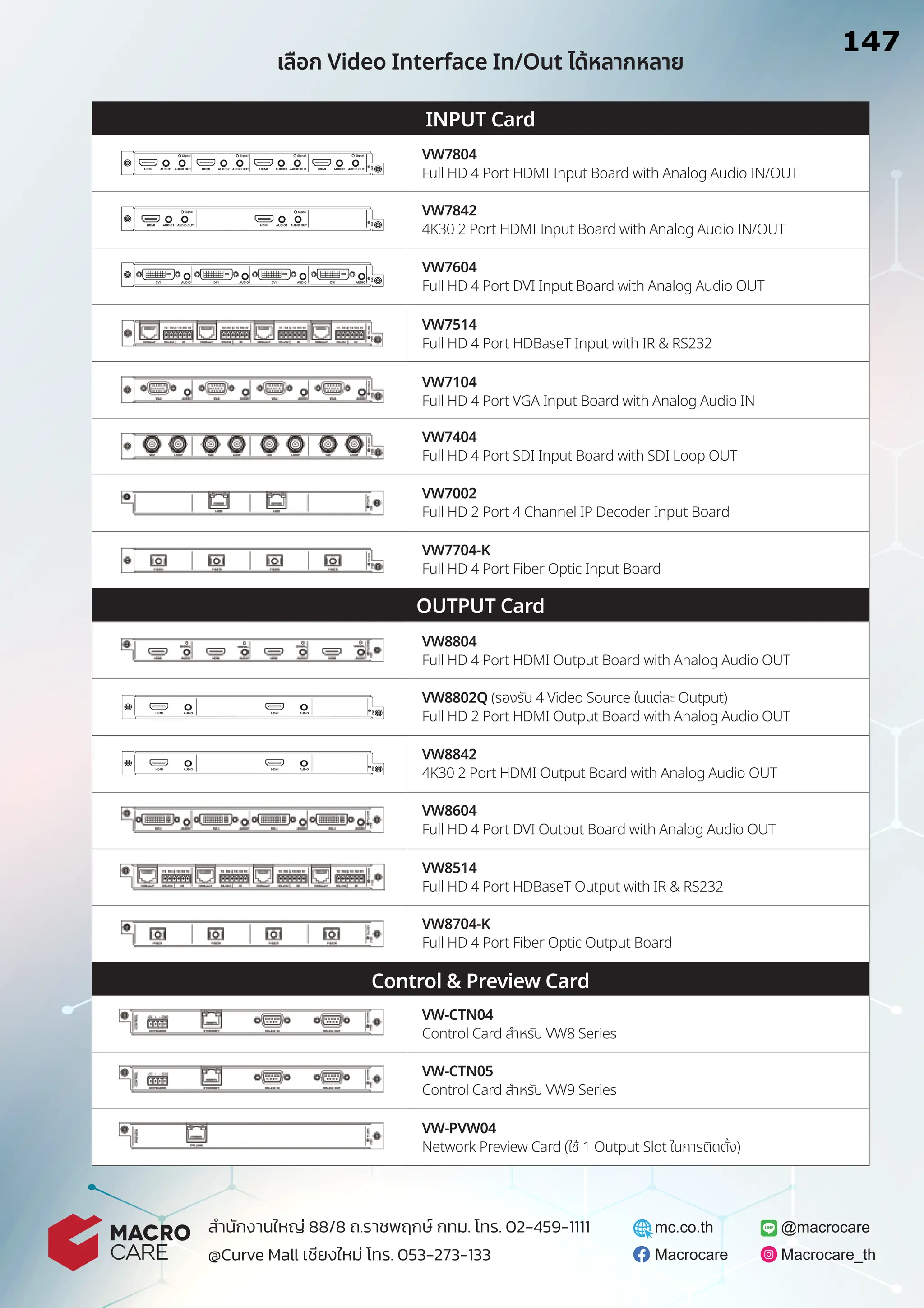
VW-CTN04
Control Card สําหรับ VW8 Series
VW-CTN05
Control Card สําหรับ VW9 Series
VW-PVW04
Network Preview Card (ใช้ 1 Output Slot ในการติดตั้ง)
@macrocare
Macrocare Macrocare_th
mc.co.th
สํานักงานใหญ่ 88/8 ถ.ราชพฤกษ์ กทม. โทร. 02-459-1111
@Curve Mall เชียงใหม่ โทร. 053-273-133
INPUT Card
OUTPUT Card
Control & Preview Card
HDMI AUDIO1 AUDIO OUT
Signal
HDMI AUDIO2 AUDIO OUT
Signal
HDMI AUDIO3 AUDIO OUT
Signal
HDMI AUDIO3 AUDIO OUT
Signal
AUDIO
DVI AUDIO
DVI AUDIO
DVI AUDIO
DVI
HDMI AUDIO1 AUDIO OUT
Signal
HDMI AUDIO1 AUDIO OUT
Signal
VW7804
Full HD 4 Port HDMI Input Board with Analog Audio IN/OUT
VW7842
4K30 2 Port HDMI Input Board with Analog Audio IN/OUT
VW7604
Full HD 4 Port DVI Input Board with Analog Audio OUT
VW7514
Full HD 4 Port HDBaseT Input with IR & RS232
VW7104
Full HD 4 Port VGA Input Board with Analog Audio IN
VW7404
Full HD 4 Port SDI Input Board with SDI Loop OUT
VW7002
Full HD 2 Port 4 Channel IP Decoder Input Board
VW7704-K
Full HD 4 Port Fiber Optic Input Board
VW8804
Full HD 4 Port HDMI Output Board with Analog Audio OUT
VW8842
4K30 2 Port HDMI Output Board with Analog Audio OUT
VW8604
Full HD 4 Port DVI Output Board with Analog Audio OUT
VW8514
Full HD 4 Port HDBaseT Output with IR & RS232
VW8704-K
Full HD 4 Port Fiber Optic Output Board
VW8802Q (รองรับ 4 Video Source ในแต่ละ Output)
Full HD 2 Port HDMI Output Board with Analog Audio OUT
147
14.7 มีช่องสัญญาณขาเข้ารวมกัน
16 ช่อง (4x1)=4ช่อง
14.8
14.5 มีช่องสัญญาณขาออกรวมกัน
16 ช่อง (4x4 =16 ช่อง )
14.6
FIBER OPTIC CABLE
ADSSFIBER OPTIC SINGLE JACKET FRP
www.focomm-cabling.com
FOCOMM (THAILAND) CO., LTD
12 Soi Sukhaphiban 5 Soi 5 Yaek 3, Tha Raeng Subdistrict,Bang Khen District Bangkok 10220
Email : info@focomm-cabling.com
Optical Fiber
Filling Compound
Loose Tube
Filler Rod Water Blocking Element
Central Strength Member
Water Blocking Tape
Outer Sheath
Additional Strength Member
(if necessary)
FRP (Flat Rodent Armor)
Rip Cord
STANDARD
- ATM, FDDI, FTTX, Fiber Channel,CATV, Communication
- ISO/IEC 11801:2007, ISO/IEC 11801:2011(Ed.2.2)
- ANSI/TIA/EIA-568-B.3, ANSI/ TIA-568-C.3, ANSI/TIA-568.3-D, ANSI/ICEA 640
- Telcordia (Bellcore)GR-20CORE, GR-409-CORE
- ANSI/ICEA 596, ICEA696, IEC61034-2, IEC60754-2, IEC60793, IEC60794-1-2
- ITU G.652D, ITU-TG 657A2
- TIA/EIA-598-C (Rev.TIA/EIA-598-A), EIA-359-A.
- IEEE802.3z, IEEE802.3ae, IEEE802.3 (LAN, Ethernet Fast Ethernet,
Gigabit Ethernet and 10 Gigabit Ethernet 40-100 Gbps)
- RoHS compliant
- TIS 2166-2548,
- Made in Thailand : MiT
Rip Cord
PRODUCT DESCRIPTION
- Provide additional mechanical protection
- low friction installation
- Excellent protection from environmental hazards
- Code colour fiber and loose tube
- The cable shall be used for duct or aerial installed
APPLICATION
- Outdoor environment with high electric field strength in the
Powercommunication system and the area where frequent
thunderhappens suitable for both aerial or duct installation.
- Ethernet LAN Network, CCTV, Network Camera, PLC
151
24.1
16.1
16.2
44.
www.focomm-cabling.com
FOCOMM (THAILAND) CO.,LTD
12 Soi Sukhaphiban 5 Soi 5 Yaek 3, Tha Raeng Subdistrict,Bang Khen District Bangkok 10220
Email : info@focomm-cabling.com
CONSTRUCTION CABLE
Element
Fiber Optic
Central strength member
Loose tube
Protective tape
Strength member
Rodent Protection Armor
Outer Sheath
Rip Cord
Filler Rod
Stranding method
Tensile Load
Overall diameter
Cable diameter
Weight
Span Length
Water Blocking Element
Width
Temperature Range
Color Stripe
S
S
D
A
e
p
y
t
e
l
b
a
C
-
Material
Material
Material
Outer Diameter
-
Material
Material
Material
Material
Thickness
Material
No.
Material
Diameter
-
-
Short term
Long term
Pressure
Diameter
Diameter (24/48 core)
(24/48 core)
Operation Temperature
Installation Temperature
Storage/Shipping Temperature
5
Silica High Grade / Compound Glass
FRP 1.8 ± 0.2 mm
PBT
2.0 ± 0.2 mm
6 fiber per tube, Thixotropic Jelly Compound
Water -blocking tape, Water blocking yarn
Aramid yarns
Inner Diameter 1.5 ± 0.2 mm
NO. OF FIBER IN EACH TUBE
No. of fiber
24
48
No. of tube
4
4
Tube color
Tube color
No. of fiber
Tube color
No. of fiber
1
Blue
6
Blue
12
2
Orange
6
Orange
12
3
Green
6
Green
12
4
Brown
6
Brown
12
5
F
F
(TIA/EIA-598-A)
3 mm ± 0.5mm
-40°C to +75°C
-40°C to +70 °C
-40°C to +70 °C
≥ 126 km/hr
Dry-core technology
40-100m
Approx. 85 / 100±10 kg/km
10.5 ± 1mm / 11.5 ± 1mm.
9.5 - 12 mm
≥ 3400 N / 10 cm
2500 N
3600 N
Lay - length 75 mm ± 5 mm
Reverse oscillating lay (ROL) technique (SZ Direction)
2.2 mm ± 0.2 mm
Polyethylene, natural Color
2
Polyester
1.8 ± 0.2 mm
Black HDPE (non Rodent Repellent/Rodent Repellent)
Nominal thickness 1.0 ± 0.2 mm
Flat FRP Non-Metaliic type (FRP: Fiber Reinforced Plastics)
152
16.3
16.7
16.5
16.6
16.9
16.8
16.12
16.11
16.10
45.
www.focomm-cabling.com
FOCOMM (THAILAND) CO.,LTD
12 Soi Sukhaphiban 5 Soi 5 Yaek 3, Tha Raeng Subdistrict,Bang Khen District Bangkok 10220
Email : info@focomm-cabling.com
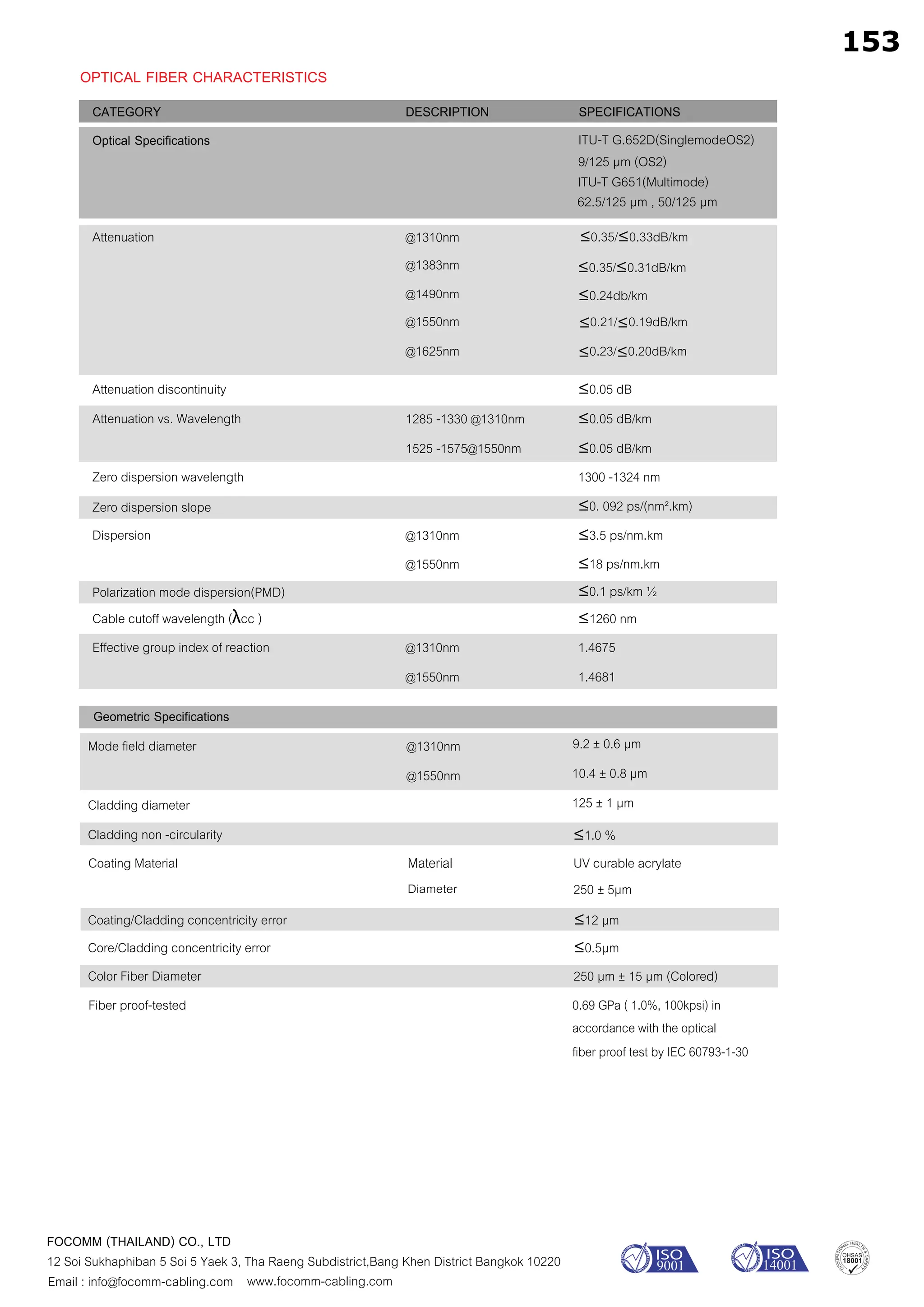
Optical Specifications
Attenuation
Attenuation discontinuity
Attenuation vs. Wavelength
Zero dispersion wavelength
Zero dispersion slope
Dispersion
Polarization mode dispersion(PMD)
Cable cutoff wavelength (λcc )
Effective group index of reaction
Geometric Specifications
Mode field diameter
Cladding diameter
Cladding non -circularity
Coating/Cladding concentricity error
Core/Cladding concentricity error
Color Fiber Diameter
@1310nm
@1383nm
@1490nm
@1550nm
@1625nm
1285 -1330 @1310nm
1525 -1575@1550nm
@1310nm
@1550nm
@1310nm
@1550nm
@1310nm
@1550nm
9.2 ± 0.6 µm
10.4 ± 0.8 µm
125 ± 1 µm
≤1.0 %
≤12 µm
≤0.5µm
250 µm ± 15 µm (Colored)
SPECIFICATIONS
DESCRIPTION
CATEGORY
OPTICAL FIBER CHARACTERISTICS
≤0.24db/km
≤0.35/≤0.33dB/km
≤0.35/≤0.31dB/km
≤0.21/≤0.19dB/km
≤0.23/≤0.20dB/km
Coating Material UV curable acrylate
250 ± 5µm
Material
Fiber proof-tested 0.69 GPa ( 1.0%, 100kpsi) in
accordance with the optical
fiber proof test by IEC 60793-1-30
Diameter
ITU-T G.652D(SinglemodeOS2)
9/125 µm (OS2)
ITU-T G651(Multimode)
62.5/125 µm , 50/125 µm
≤0.05 dB
≤0.05 dB/km
≤0.05 dB/km
1300 -1324 nm
≤0. 092 ps/(nm².km)
≤3.5 ps/nm.km
≤18 ps/nm.km
≤0.1 ps/km ½
≤1260 nm
1.4675
1.4681
153
16.4
46.
www.focomm-cabling.com
FOCOMM (THAILAND) CO.,LTD
12 Soi Sukhaphiban 5 Soi 5 Yaek 3, Tha Raeng Subdistrict,Bang Khen District Bangkok 10220
Email : info@focomm-cabling.com
Mechanical Specifications
Proof test level
Fiber curl radius
Peak coating strip force
Relative humidity
≥1.0 %
≥4.0 m
1.3 - 8.9N
Up to 90%, no frost
Maximum Span Length
Maximum Wind Velocity
Max. Tensile load
Maximum Crush resistance
Minimum bending Radius
Sag 0.5%
Sag 1.0%
Installation
Operation
Installation
Operation
40 m.
80 m.
126 km./hr.
3,600 N. for 6-96 Cores
2,500 N. for 6-96 Cores
3,400 N./10 cm.
20 x Diameter of Cable
10 x Diameter of Cable
SPECIFICATIONS
DESCRIPTION
CATEGORY
OPTICAL FIBER CHARACTERISTICS
IDENTIFICATION COLOR CODE OF FIBER AND LOOSE TUBE
1
2
3
Blue
Orange
Green
The color code of the loose tubes and the individual fibers within each loose tube shall be in accordance TIA/EIA-598-C
(Rev.TIA/EIA-598-A) and EIA-359-A
NO. FIBER COLOR LOOSE TUBE COLOR
5
6
7
Slate
White
Red
9
10
11
Yellow
Violet
Rose
4
8
12
Brown
Black
Aqua
Blue
Orange
Green
Slate
White
Red
Yellow
Violet
Rose
Brown
Black
Aqua
- Cable type and number of optical fiber
- Manufacturer name
- Month and Year of Manufacture
- Cable length
The sequential number of the cable length shall be marked on the outer sheath of the cable at an interval of 1meter ± 1%
- Logo and Thai word
PACKING AND DRUM
Both ends of cable are securely
Cable Packing 4000m/reel.
The cable is rounded on a non-returnable wooden drum.
fastened to drum and sealed with a shrinkable cap to prevent ingress of moisture. The following information shall be marked
on the outer sheath of the cable at an interval of about 1 meter.
154
47.
www.focomm-cabling.com
FOCOMM (THAILAND) CO.,LTD
12 Soi Sukhaphiban 5 Soi 5 Yaek 3, Tha Raeng Subdistrict,Bang Khen District Bangkok 10220
Email : info@focomm-cabling.com
TEST REQUIREMENTS
Tensile test
IEC 60794-1-2-E1A
TIA/EIA-455-33A
Crush or Compression test
IEC 60794-1-2-E3
TIA/EIA-455-41A
Impact test
IEC 60794-1-2-E4
TIA/EIA-455-25C
Torsion or Twist test
IEC 60794-1-2-E7
TIA/EIA-455-85A
Repeated bending
Cable bending Test
IEC 60794-1-2-E6,
TIA/EIA-455-104A
IEC 60794-1-2-E11B
Temperature cycling test
IEC 60794-1-2-F1
TIA/EIA-455-3A
Water penetration test
IEC 60794-1-2-F5
TIA/EIA-455-82B
Drip test
IEC 60794-1-2-E14
a
i
r
e
t
i
r
c
e
c
n
a
t
p
e
c
c
A
d
o
h
t
e
M
m
e
t
I
- Max. tensile strength: 3600 N
- Sample length: 100 meters
- Times: 1 hour
- Load: 4400 N
- Time: 10 minutes
- Length: 100 mm
- Impact energy: 450 g
- Height: 1 meter
- Impact points: min.1
- Number of impacts: 5
- 1 m cable length with 150 N weight
- ±180° ,10 cycles
- Radius = 20 × cable outer diameter
- 1m cable length with 150 N weight, 30 cycles
- Water height: 1m
- Sample length:3m
- Duration of test: 24hrs
- Five 0.3m samples suspended vertically in a climate
chamber, raised temperature to +70o
C
-Fiber strain at maximum
-Load max. 0.33 %
-Attenuation increase ≤ 0.1dB
-No splits or cracks in the outer jacket
-Attenuation increase ≤ 0.10 dB
- No splits or cracks in the outer jacket
-Attenuation increase ≤ 0.10 dB (after the test)
- No splits or cracks in the outer jacket
-Attenuation increase ≤ 0.10 dB (after the test)
- No splits or cracks in the outer jacket
-Attenuation increase ≤ 0.10 dB (after the test)
-Attenuation variation for reference
value(the attenuation to be measured before
test at +20±3 ) ≤0.10dB/km
-No water leakage at the end of the sample
-No filling compound shall drip from tubes after 24 hrs.
- Temperature step: +20 o
C -40 o
C+70 o
C-40 o
C
+70 o
C+20 o
C
- Time per each step: 16 hrs.
- Number of cycles: 2 cycles
ORDER INFORMATION
F - ML - ADSS - FRP9
(No. Fiber)
06 = 6 core fiber
12 = 12 core fiber
24 = 24 core fiber
48 = 48 core fiber
96 = 96 core fiber
120 = 120 core fiber
xx xx xx
04 = 4 core fiber
(Jacket Material)
H = HDPE
L = LSZH
R = RODENT
(Jacket)
SJ = Single Jacket
155
16.4
16.F-ML-ADSS-FRP9-24-R-SJ
FEATURE
OVERVIEW
- Class 1laser product EN 60825-1 standards
- Compliant with SFP MSA and SFF-8472
- Compliant with SDH/SONET
- Duplex LC connector
- Hot pluggable
- 3.3V Single Power Supply
APPLICATIONS
- Data-rate of 1.25Gbps operation
- 850nm VCSEL laser and PIN photodetector
- 1310nm FP laser and PIN photodetector for 10-40km transmission
- 1550nm DFB laser and PIN photodetector for 80-120km transmission
- Compliant with SFP MSA and SFF-8472 with duplex LC receptacle
- Digital Diagnostic Monitoring: Internal Calibration or External Calibration
- Temperature , Supply voltage , Transmitted bias current,
- Transmitted power, Received power
- 550m transmission with 50/125µm MMF
- 270m transmission with 62.5/125µm MMF
- Compatible with SONET OC-24-LR-1, Compatible with RoHS
- +3.3V single power supply
- Operating case temperature range of 0°C to +70°C (Standard)
or -40°C to +85°C (Industrial)
SFP MODULE SYSTEM PRODUCTS
1.25Gbps SFP Optical Transceiver, 550m-120km Reach
www.focomm-cabling.com
FOCOMM (THAILAND) CO., LTD
12 Soi Sukhaphiban 5 Soi 5 Yaek 3, Tha Raeng Subdistrict,Bang Khen District Bangkok 10220
Email : info@focomm-cabling.com
- SDH STM-1, S-1.1,L-1.1, L-1.2
- SONET OC-3 IR1, LR1, LR2
- Router/Server interface
- Other optical transmission systems
RECOMMENDED INTERFACE CIRCUIT MECHANICAL DIMENSIONS
162
17.2
17.1
55.
DESCRIPTION
Model
MC-SFP-SX-MM-0205
MC-SFP-LX-SM-0210
MC-SFP-LX-SM-0240
MC-SFP-ZX-SM-0280
MC-SFP-ZX-SM-02120
Rate
1.25G
1.25G
1.25G
1.25G
1.25G
Wavelength
850nm
1310nm
1310nm
1550nm
1550nm
Distance
550m
10km
40km
80km
120km
Optical power
-9~-3dBm
-9~-3dBm
-5~0dBm
0~5dBm
0~5dBm
Sensitivity
<-17dBm
<-22dBm
<-24dBm
<-25dBm
<-32dBm
ORDER INFOMATION
850nm,1.25Gbps, LC, 550m, 0°C~+70°C
1310nm, 1.25Gbps, LC, 10km, 0°C~+70°C
1310nm, 1.25Gbps, LC, 20km, 0°C~+70°C
1310nm, 1.25Gbps, LC, 40km, 0°C~+70°C
1550nm, 1.25Gbps, LC, 80km, 0°C~+70°C
1550nm, 1.25Gbps, LC, 120km, 0°C~+70°C
PRODUCT PART NUMBER
MC-SFP-SX-MM-0205
MC-SFP-LX-SM-0210
MC-SFP-LX-SM-0220
MC-SFP-LX-SM-0240
MC-SFP-ZX-SM-0280
MC-SFP-ZX-SM-02120
ABSOLUTE MAXIMUM RATINGS
RECOMMENDED OPERATING CONDITIONS
Parameter
Storage Temperature
Supply Voltage
Operating Humidity
Symbol
Vcc
Ts
Min
-0.5
-40
5
Max
4.5
+85
85
Unit
V
°C
%
Parameter
Operating Case Temperature
Power Supply Voltage
Power Supply Current
Data Rate
Commercial
Industrial
Gigabit Ethernet
Fiber Channel
Symbol
Tc
Vcc
Icc
Min
0
-40
3.13
Typical
3.3
1.25
1.063
Max
+70
+85
3.47
300
Unit
°C
V
mA
°C
Gbps
Gbps
REGULATIRY COMPLIANCE
Feature
Electrostatic Discharge (ESD) tothe Electrical Pins
Electromagnetic Interference(EMI)
Laser Eye Safety
Component Recognition
Green Products
Standard
MIL-STD-883E Method 3015.7
FCC Part 15 Class B
FDA 21CFR 1040.10 and 1040.11
EN60950, EN (IEC) 60825-1,2
UL and CUL
2002/95/EC 2005/618/EC
Performance
Class 1(>500 V) Isolation with the case
Compatible with standards
Compatible with Class I laser product.
Compatible with TüV standards
UL file E317337
RoHS6
163
17.5
17.3 17
17.4
Shenzhen Opplei TechnologiesCo., Ltd
Website: www.opplei.com/en
Lightning Protection Solutions
AC module SPD
Model: PC40-385/2
APPLICATIONS
FEATURES
Nominal working voltage Un
Max. continuous operating voltage Uc
Nominal discharge current
(8/20µs)
In
Max. discharge current (8/20µs)
Imax
Protection level @20kA , 8/20µs Up
Response time tA
Protection model
50/60Hz
220/380V, 230/440V
385V
20kA
40kA
1700V
25ns
L/ N-PE
:
:
:
:
:
:
:
:
:
:
:
:
:
:
Mounting
Connecting diameter
IP code
Working conditions
Test standards
Dimension
Weight per unit
- C class Surge Protective Device for AC Power System.
- Sensitive electronic equipment
- Telecom centers
- Automatic control centers
- Intelligent buildings
- Industrial enterprises
- Medical institutes
- DIN rail mounting for easy installation
- Plug connectors for quick and easy connection or rewiring ●40kA maximum surge current
- Thermal disconnect device
- Status indicators visually verify protection level
- Surge protection device with N-PE residual current spark gap as 3+1 circuit
35mm DIN rail
≥10mm2
IP20
Temperature: -40 to 80o
C
Relative humidity: ≤95o
C
CE, FCC, RoHS, ISO9001
90 (H)×68 (W)×36(L)mm
200g
Electrical parameter
TECHNICAL PARAMETER
General data
165
18.1
18.2
18.9
18.8
18.5
18.4
18.10
18.7
18.3
18
ELECTRICAL AND ELECTRONICPRODUCTS TESTING CENTER
National Science and Technology Development Agency
REPORT No. 10 / 65-161 Page 1 of 25
This test report is test results from the EUT only, not the product’s quality certificate. It shall not be reproduced except in full without the written approval of testing laboratory.
141 Thailand Science Park (TSP) Innovation Cluster 2 Tower D, Phahonyothin Road Khlong Nueng, Khlong Luang Pathum Thani 12120 Thailand
Tel 02-117-8600, Fax 02-117-8625, website www.ptec.or.th
PTEC-LB-FR-10 REV.1/02-01-19
TEST REPORT
Report No. ...................................... : 10/65-161
Equipment Under Test (EUT) No...: EM-65-0583
TISI No. ........................................... : -
Testing Laboratory.........................: Electrical and Electronic Products Testing Center
Address............................................ : 141 Thailand Science Park, Innovation Cluster 2 Tower D,
Phahonyothin Road, Khlong Nueng, Klong Luang,
Pathum Thani 12120, Thailand.
Applicant’s name............................: Success Network and Communication Company Limited
Address............................................ : 12 Soi Sukhaphiban 5 Soi 5 Intersection 3, Tha Raeng,
Bang Khen, Bangkok 10220
Manufacturer’s Name.................... : Opplei Technologies Co., Ltd.
Address............................................ : -
Standard .......................................... : IEC 61000-4-5:2017
Non-standard test method.........................: -
Test item description .................... : AC module SPD
Trademark ....................................... : Opplei
Model/Type reference...................... : PC40-385
S/N……………………………………..: -
Ratings............................................. : -
Date of receive ................................ : 26 July 2022
Date of tested .................................. : 5, 15 August 2022
Date of issue: .................................. : 30 August 2022
Tested by
_______________________
(MR. Itsarapong Poolpram)
Engineer
Approved by
_______________________
(MR. Anake Meemoosor)
Operation Manager
167
18.11
60.
ELECTRICAL AND ELECTRONICPRODUCTS TESTING CENTER
National Science and Technology Development Agency
REPORT No. 10 / 65-161 Page 2 of 25
This test report is test results from the EUT only, not the product’s quality certificate. It shall not be reproduced except in full without the written approval of testing laboratory.
141 Thailand Science Park (TSP) Innovation Cluster 2 Tower D, Phahonyothin Road Khlong Nueng, Khlong Luang Pathum Thani 12120 Thailand
Tel 02-117-8600, Fax 02-117-8625, website www.ptec.or.th
PTEC-LB-FR-10 REV.1/02-01-19
CONTENTS
1SUMMARYOFTESTING 3
2.1TEST PLAN 4
2.2DEVIATIONS FROM STANDARD 4
3TESTCONDITIONS 5
3.1OPERATION MODE 5
3.2UNCERTAINTY APPLICATION 5
3.3EQUIPMENT CLASSIFICATIONS 7
3.4PROTECTION CLASSIFICATIONS 7
3.5PERFORMANCE CRITERIA OF TEST SPECIFICATION 7
3.6EUTFUNCTION MONITORING 7
4TESTSYSTEMCONFIGURATION 7
4.1EUTEXERCISE SOFTWARE 7
4.2EUTMODIFICATIONS 7
5EUTDESCRIPTION 8
5.1EUTSPECIFICATION 8
5.2EUTCONFIGURATION 8
5.3PERIPHERALS DESCRIPTION 8
5.4CABLES DESCRIPTION 8
6TESTSETUPANDRESULT 9
6.1 TEST ITEM:SURGE 9
168
61.
ELECTRICAL AND ELECTRONICPRODUCTS TESTING CENTER
National Science and Technology Development Agency
REPORT No. 10 / 65-161 Page 3 of 25
This test report is test results from the EUT only, not the product’s quality certificate. It shall not be reproduced except in full without the written approval of testing laboratory.
141 Thailand Science Park (TSP) Innovation Cluster 2 Tower D, Phahonyothin Road Khlong Nueng, Khlong Luang Pathum Thani 12120 Thailand
Tel 02-117-8600, Fax 02-117-8625, website www.ptec.or.th
PTEC-LB-FR-10 REV.1/02-01-19
1 SUMMARY OF TESTING
This product was tested and complied according to following specification standards:
IEC 61000-4-5 Electromagnetic compatibility (EMC) - Part 4-5: Testing and measurement techniques -
Surge immunity test.
Test Item Test Specification Test Method Result
Surge
IEC 61000-4-5:2017
1.2/50us, 1kV, 2kV, 3kV, 4kV, 5kV, and 6kV
IEC61000-4-5:2017
(Ed 2.0)
Normal Operated
Note: -
169
62.
ELECTRICAL AND ELECTRONICPRODUCTS TESTING CENTER
National Science and Technology Development Agency
REPORT No. 10 / 65-161 Page 4 of 25
This test report is test results from the EUT only, not the product’s quality certificate. It shall not be reproduced except in full without the written approval of testing laboratory.
141 Thailand Science Park (TSP) Innovation Cluster 2 Tower D, Phahonyothin Road Khlong Nueng, Khlong Luang Pathum Thani 12120 Thailand
Tel 02-117-8600, Fax 02-117-8625, website www.ptec.or.th
PTEC-LB-FR-10 REV.1/02-01-19
2 TEST PLAN AND DEVIATIONS FROM STANDARD
2.1 Test Plan
No. Test Item
Input
Voltage
Mode Test Port Test Specification
1 Surge - A AC Port
IEC 61000-4-5:2017
1.2/50us, 1kV, 2kV, 3kV, 4kV, 5kV, and 6kV
2.2 Deviations from standard
-
170
63.
ELECTRICAL AND ELECTRONICPRODUCTS TESTING CENTER
National Science and Technology Development Agency
REPORT No. 10 / 65-161 Page 5 of 25
This test report is test results from the EUT only, not the product’s quality certificate. It shall not be reproduced except in full without the written approval of testing laboratory.
141 Thailand Science Park (TSP) Innovation Cluster 2 Tower D, Phahonyothin Road Khlong Nueng, Khlong Luang Pathum Thani 12120 Thailand
Tel 02-117-8600, Fax 02-117-8625, website www.ptec.or.th
PTEC-LB-FR-10 REV.1/02-01-19
3 TEST CONDITIONS
3.1 Operation Mode
A: Normal Operated.
3.2 Uncertainty Application
3.2.1 Uncertainty application according to CISPR 16-4-2 for Conducted Emission, Radiated
Disturbance and Disturbance Power Testing.
Compliance or Non-Compliance with a disturbance limit was determined in the following manner
If Ulab is less than or equal to Ucispr in table 1, then:
- Compliance is deemed to occur if no measured disturbance exceeds the disturbance limit.
- Non-Compliance is deemed to occur if any measured disturbance exceeds the disturbance
limit.
If Ulab is greater than Ucispr in table 1, then:
- Compliance is deemed to occur if no measured disturbance, increased by
( Ulab- Ucispr), exceeds the disturbance limit.
- Non-Compliance is deemed to occur if any measured disturbance, increased by
( Ulab-Ucispr), exceeds the disturbance limit.
Table 1 - Values of Ucispr
Abbreviation Testing system Frequency range Ulab Ucispr Ulab- Ucispr
CE Conducted Emission 9 kHz - 150 kHz 2.88 4.00 -1.12
CE Conducted Emission 150 kHz - 30 MHz 3.51 3.60 -0.09
RE Radiated Disturbance 30 MHz - 1000 MHz 4.80 5.20 -0.40
RE Radiated Disturbance 1 GHz - 6 GHz 5.11 5.2 -0.09
PE Disturbance Power 30 MHz - 300 MHz 2.42 4.50 -2.08
171
64.
ELECTRICAL AND ELECTRONICPRODUCTS TESTING CENTER
National Science and Technology Development Agency
REPORT No. 10 / 65-161 Page 6 of 25
This test report is test results from the EUT only, not the product’s quality certificate. It shall not be reproduced except in full without the written approval of testing laboratory.
141 Thailand Science Park (TSP) Innovation Cluster 2 Tower D, Phahonyothin Road Khlong Nueng, Khlong Luang Pathum Thani 12120 Thailand
Tel 02-117-8600, Fax 02-117-8625, website www.ptec.or.th
PTEC-LB-FR-10 REV.1/02-01-19
Frequency
10
This is the estimated
uncertainty of our
applied level.
We have at least 95 %
confidence that the
actual applied level is
In this range but only
a 50 % confidence that
the required level has
been reached.
Required
Immunity
Test level to apply which gives
a 95 % confidence that
specified level has been
achieved is the standard
uncertainty multiplied by a
factor k=1.64
3.2.2 Uncertainty Application according to LAB 34 for other testing system.
Pass
Case A
The measured result is
within the limit, even
when extended by the
uncertainty interval. The
product therefore
complies with the
specification.
Unjudged in
Case B
The measured result is
below the upper limit,
but by a margin less
than half of the
uncertainty interval; it is
therefore not possible to
state compliance based
on the 95% level of
confidence. However,
the result indicates that
compliance is more
probable than non-
compliance.
Unjudged in
Case C
The measured result is
above the upper limit,
but by a margin less
than half of the
uncertainty interval; it is
therefore not possible to
state non-compliance
based on the 95% level
of confidence. However,
the result indicates that
non-compliance is more
probable than
compliance.
Fail
Case D
The measured result is
beyond the upper limit,
even when extended
downwards by half of
the uncertainty interval.
The product therefore
does not comply with the
specification.
3.2.3 Uncertainty Application for immunity testing.
Uncertainty of each test systems are applied for compliance with related standard according
to LAB 34
= measured result
= uncertainty interval
Immunity
Test level
172
65.
ELECTRICAL AND ELECTRONICPRODUCTS TESTING CENTER
National Science and Technology Development Agency
REPORT No. 10 / 65-161 Page 7 of 25
This test report is test results from the EUT only, not the product’s quality certificate. It shall not be reproduced except in full without the written approval of testing laboratory.
141 Thailand Science Park (TSP) Innovation Cluster 2 Tower D, Phahonyothin Road Khlong Nueng, Khlong Luang Pathum Thani 12120 Thailand
Tel 02-117-8600, Fax 02-117-8625, website www.ptec.or.th
PTEC-LB-FR-10 REV.1/02-01-19
3.3 Equipment Classifications
-
3.4 Protection Classifications
-
3.5 Performance Criteria of Test Specification
-
3.6 EUT Function Monitoring
-
4 TEST SYSTEM CONFIGURATION
4.1 EUT Exercise Software
-
4.2 EUT Modifications
-
173
66.
ELECTRICAL AND ELECTRONICPRODUCTS TESTING CENTER
National Science and Technology Development Agency
REPORT No. 10 / 65-161 Page 8 of 25
This test report is test results from the EUT only, not the product’s quality certificate. It shall not be reproduced except in full without the written approval of testing laboratory.
141 Thailand Science Park (TSP) Innovation Cluster 2 Tower D, Phahonyothin Road Khlong Nueng, Khlong Luang Pathum Thani 12120 Thailand
Tel 02-117-8600, Fax 02-117-8625, website www.ptec.or.th
PTEC-LB-FR-10 REV.1/02-01-19
5 EUT DESCRIPTION
5.1 EUT Specification
Input Voltage -
Input Current/Power -
Clock/Oscillator -
5.2 EUT Configuration
FIGURE 1 - EUT and EUT Configuration.
5.3 Peripherals Description
Diagram Description Trade Name Model Serial Number
- - - - -
5.4 Cables Description
Ref Cable Type Shield
Length
(meters)
Ferrite Connector
Connection
Point 1
Connection
Point 2
- - - - - - - -
L
G
EUT
N
174
67.
ELECTRICAL AND ELECTRONICPRODUCTS TESTING CENTER
National Science and Technology Development Agency
REPORT No. 10 / 65-161 Page 9 of 25
This test report is test results from the EUT only, not the product’s quality certificate. It shall not be reproduced except in full without the written approval of testing laboratory.
141 Thailand Science Park (TSP) Innovation Cluster 2 Tower D, Phahonyothin Road Khlong Nueng, Khlong Luang Pathum Thani 12120 Thailand
Tel 02-117-8600, Fax 02-117-8625, website www.ptec.or.th
PTEC-LB-FR-10 REV.1/02-01-19
6 TEST SETUP AND RESULT
6.1 Test Item: Surge
6.1.1 Test Setup
Test Specification
See 1 and 2.1
Test Equipment
Equipment Name Manufacture Model S/N Traceability Due date
Surge Simulator TESEQ
NSG3060, CWM 3650,
CDN 3663
1637/0535/2110 NIST 25-09-22
Oscilloscope Tektronix MDO3052 C043852 NIMT 10-01-23
Probe KeyTek PK1001D 9909188 PTEC 21-04-23
Customer’s Equipment
Equipment Name Manufacture Model S/N Traceability Due date
- - - - - -
Test Location: Test area
Test Environment
Temperature : (°C) 24 Humidity (%) 52
Test Setup Description
The EUT was placed on the 80 cm height isolator above the ground reference plane. The EUT was arranged
and connected to the auxiliary equipment for operating. The distance from the EUT to the other conductive
materials was more than 1 m.
For the Surge testing was used for coupling the surge to the EUT. The EUT configuration for the surge
immunity testing is shown in FIGURE 2 and 3 respectively.
175
68.
ELECTRICAL AND ELECTRONICPRODUCTS TESTING CENTER
National Science and Technology Development Agency
REPORT No. 10 / 65-161 Page 10 of 25
This test report is test results from the EUT only, not the product’s quality certificate. It shall not be reproduced except in full without the written approval of testing laboratory.
141 Thailand Science Park (TSP) Innovation Cluster 2 Tower D, Phahonyothin Road Khlong Nueng, Khlong Luang Pathum Thani 12120 Thailand
Tel 02-117-8600, Fax 02-117-8625, website www.ptec.or.th
PTEC-LB-FR-10 REV.1/02-01-19
Test Picture
FIGURE 2 - The setup diagram.
FIGURE 3 - The test setup picture.
EUT
Surge
Generator
Oscilloscope
Probe
176
69.
ELECTRICAL AND ELECTRONICPRODUCTS TESTING CENTER
National Science and Technology Development Agency
REPORT No. 10 / 65-161 Page 11 of 25
This test report is test results from the EUT only, not the product’s quality certificate. It shall not be reproduced except in full without the written approval of testing laboratory.
141 Thailand Science Park (TSP) Innovation Cluster 2 Tower D, Phahonyothin Road Khlong Nueng, Khlong Luang Pathum Thani 12120 Thailand
Tel 02-117-8600, Fax 02-117-8625, website www.ptec.or.th
PTEC-LB-FR-10 REV.1/02-01-19
6.1.2 Test Result
Surge 1 KV Waveform
TABLE: Electrical data Surge
No.
Surge Simulator Test results polarity (V)
Remark
level (V) Polarity Test Line Maximum Minimum
1 + 1000 Positive L-N 970.0 -57.03 Graph No.1
2 - 1000 Negative L-N 12.91 -999.0 Graph No.2
Waveform after connected the EUT
TABLE: Electrical data Surge
No.
Surge Simulator Test results polarity (V)
Remark
level (V) Polarity Test Line Maximum Minimum
1 + 1000 Positive L-N 1005.0 6.875 Graph No.3
2 - 1000 Negative L-N 8.313 -1004 Graph No.4
Phenomena Observed/Comments
-
Surge 2 KV Waveform
TABLE: Electrical data Surge
No.
Surge Simulator Test results polarity (V)
Remark
level (V) Polarity Test Line Maximum Minimum
1 + 2000 Positive L-N 1956 -157.3 Graph No.5
2 - 2000 Negative L-N 105.5 -2.021 Graph No.6
Waveform after connected the EUT
TABLE: Electrical data Surge
No.
Surge Simulator Test results polarity (V)
Remark
level (V) Polarity Test Line Maximum Minimum
1 + 2000 Positive L-N 1799 -94.45 Graph No.7
2 - 2000 Negative L-N 134.4 -1765 Graph No.8
Phenomena Observed/Comments
-
177
70.
ELECTRICAL AND ELECTRONICPRODUCTS TESTING CENTER
National Science and Technology Development Agency
REPORT No. 10 / 65-161 Page 12 of 25
This test report is test results from the EUT only, not the product’s quality certificate. It shall not be reproduced except in full without the written approval of testing laboratory.
141 Thailand Science Park (TSP) Innovation Cluster 2 Tower D, Phahonyothin Road Khlong Nueng, Khlong Luang Pathum Thani 12120 Thailand
Tel 02-117-8600, Fax 02-117-8625, website www.ptec.or.th
PTEC-LB-FR-10 REV.1/02-01-19
Surge 3 KV Waveform
TABLE: Electrical data Surge
No.
Surge Simulator Test results polarity (V)
Remark
level (V) Polarity Test Line Maximum Minimum
1 + 3000 Positive L-N 2981 -272.2 Graph No.9
2 - 3000 Negative L-N 241.7 -3040 Graph No.10
Waveform after connected the EUT
TABLE: Electrical data Surge
No.
Surge Simulator Test results polarity (V)
Remark
level (V) Polarity Test Line Maximum Minimum
1 + 3000 Positive L-N 1957 -402.3 Graph No.11
2 - 3000 Negative L-N 434.1 -1966 Graph No.12
Phenomena Observed/Comments
-
Surge 4 KV Waveform
TABLE: Electrical data Surge
No.
Surge Simulator Test results polarity (V)
Remark
level (V) Polarity Test Line Maximum Minimum
1 + 4000 Positive L-N 3989 -455.9 Graph No.13
2 - 4000 Negative L-N 449.1 -4068 Graph No.14
Waveform after connected the EUT
TABLE: Electrical data Surge
No.
Surge Simulator Test results polarity (V)
Remark
level (V) Polarity Test Line Maximum Minimum
1 + 4000 Positive L-N 2079 -649.3 Graph No.15
2 - 4000 Negative L-N 679.6 -2069 Graph No.16
Phenomena Observed/Comments
-
178
71.
ELECTRICAL AND ELECTRONICPRODUCTS TESTING CENTER
National Science and Technology Development Agency
REPORT No. 10 / 65-161 Page 13 of 25
This test report is test results from the EUT only, not the product’s quality certificate. It shall not be reproduced except in full without the written approval of testing laboratory.
141 Thailand Science Park (TSP) Innovation Cluster 2 Tower D, Phahonyothin Road Khlong Nueng, Khlong Luang Pathum Thani 12120 Thailand
Tel 02-117-8600, Fax 02-117-8625, website www.ptec.or.th
PTEC-LB-FR-10 REV.1/02-01-19
Surge 5 KV Waveform
TABLE: Electrical data Surge
No.
Surge Simulator Test results polarity (V)
Remark
level (V) Polarity Test Line Maximum Minimum
1 + 5000 Positive L-N 4965 -666.1 Graph No.17
2 - 5000 Negative L-N 641.6 -4992 Graph No.18
Waveform after connected the EUT
TABLE: Electrical data Surge
No.
Surge Simulator Test results polarity (V)
Remark
level (V) Polarity Test Line Maximum Minimum
1 + 5000 Positive L-N 2158 -833.7 Graph No.19
2 - 5000 Negative L-N 859.4 -2141 Graph No.20
Phenomena Observed/Comments
-
Surge 6 KV Waveform
TABLE: Electrical data Surge
No.
Surge Simulator Test results polarity (V)
Remark
level (V) Polarity Test Line Maximum Minimum
1 + 6000 Positive L-N 5967 -903.8 Graph No.21
2 - 6000 Negative L-N 875.2 -6017 Graph No.22
Waveform after connected the EUT
TABLE: Electrical data Surge
No.
Surge Simulator Test results polarity (V)
Remark
level (V) Polarity Test Line Maximum Minimum
1 + 6000 Positive L-N 2222 -818.4 Graph No.23
2 - 6000 Negative L-N 835.9 -2199 Graph No.24
Phenomena Observed/Comments
-
Tested by: MR. Itsarapong Poolpram
179
72.
ELECTRICAL AND ELECTRONICPRODUCTS TESTING CENTER
National Science and Technology Development Agency
REPORT No. 10 / 65-161 Page 14 of 25
This test report is test results from the EUT only, not the product’s quality certificate. It shall not be reproduced except in full without the written approval of testing laboratory.
141 Thailand Science Park (TSP) Innovation Cluster 2 Tower D, Phahonyothin Road Khlong Nueng, Khlong Luang Pathum Thani 12120 Thailand
Tel 02-117-8600, Fax 02-117-8625, website www.ptec.or.th
PTEC-LB-FR-10 REV.1/02-01-19
Graph of result
Graph No.1 Surge 1KV Waveform (Positive Polarity)
Graph No.2 Surge 1KV Waveform (Negative Polarity)
180
73.
ELECTRICAL AND ELECTRONICPRODUCTS TESTING CENTER
National Science and Technology Development Agency
REPORT No. 10 / 65-161 Page 15 of 25
This test report is test results from the EUT only, not the product’s quality certificate. It shall not be reproduced except in full without the written approval of testing laboratory.
141 Thailand Science Park (TSP) Innovation Cluster 2 Tower D, Phahonyothin Road Khlong Nueng, Khlong Luang Pathum Thani 12120 Thailand
Tel 02-117-8600, Fax 02-117-8625, website www.ptec.or.th
PTEC-LB-FR-10 REV.1/02-01-19
Graph No.3 Waveform after connected the EUT (Positive Polarity)
Graph No.4 Waveform after connected the EUT (Negative Polarity)
181
74.
ELECTRICAL AND ELECTRONICPRODUCTS TESTING CENTER
National Science and Technology Development Agency
REPORT No. 10 / 65-161 Page 16 of 25
This test report is test results from the EUT only, not the product’s quality certificate. It shall not be reproduced except in full without the written approval of testing laboratory.
141 Thailand Science Park (TSP) Innovation Cluster 2 Tower D, Phahonyothin Road Khlong Nueng, Khlong Luang Pathum Thani 12120 Thailand
Tel 02-117-8600, Fax 02-117-8625, website www.ptec.or.th
PTEC-LB-FR-10 REV.1/02-01-19
Graph No.5 Surge 2KV Waveform (Positive Polarity)
Graph No.6 Surge 2KV Waveform (Negative Polarity)
182
75.
ELECTRICAL AND ELECTRONICPRODUCTS TESTING CENTER
National Science and Technology Development Agency
REPORT No. 10 / 65-161 Page 17 of 25
This test report is test results from the EUT only, not the product’s quality certificate. It shall not be reproduced except in full without the written approval of testing laboratory.
141 Thailand Science Park (TSP) Innovation Cluster 2 Tower D, Phahonyothin Road Khlong Nueng, Khlong Luang Pathum Thani 12120 Thailand
Tel 02-117-8600, Fax 02-117-8625, website www.ptec.or.th
PTEC-LB-FR-10 REV.1/02-01-19
Graph No.7 Waveform after connected the EUT (Positive Polarity)
Graph No.8 Waveform after connected the EUT (Negative Polarity)
183
76.
ELECTRICAL AND ELECTRONICPRODUCTS TESTING CENTER
National Science and Technology Development Agency
REPORT No. 10 / 65-161 Page 18 of 25
This test report is test results from the EUT only, not the product’s quality certificate. It shall not be reproduced except in full without the written approval of testing laboratory.
141 Thailand Science Park (TSP) Innovation Cluster 2 Tower D, Phahonyothin Road Khlong Nueng, Khlong Luang Pathum Thani 12120 Thailand
Tel 02-117-8600, Fax 02-117-8625, website www.ptec.or.th
PTEC-LB-FR-10 REV.1/02-01-19
Graph No.9 Surge 3KV Waveform (Positive Polarity)
Graph No.10 Surge 3KV Waveform (Negative Polarity)
184
77.
ELECTRICAL AND ELECTRONICPRODUCTS TESTING CENTER
National Science and Technology Development Agency
REPORT No. 10 / 65-161 Page 19 of 25
This test report is test results from the EUT only, not the product’s quality certificate. It shall not be reproduced except in full without the written approval of testing laboratory.
141 Thailand Science Park (TSP) Innovation Cluster 2 Tower D, Phahonyothin Road Khlong Nueng, Khlong Luang Pathum Thani 12120 Thailand
Tel 02-117-8600, Fax 02-117-8625, website www.ptec.or.th
PTEC-LB-FR-10 REV.1/02-01-19
Graph No.11 Waveform after connected the EUT (Positive Polarity)
Graph No.12 Waveform after connected the EUT (Negative Polarity)
185
78.
ELECTRICAL AND ELECTRONICPRODUCTS TESTING CENTER
National Science and Technology Development Agency
REPORT No. 10 / 65-161 Page 20 of 25
This test report is test results from the EUT only, not the product’s quality certificate. It shall not be reproduced except in full without the written approval of testing laboratory.
141 Thailand Science Park (TSP) Innovation Cluster 2 Tower D, Phahonyothin Road Khlong Nueng, Khlong Luang Pathum Thani 12120 Thailand
Tel 02-117-8600, Fax 02-117-8625, website www.ptec.or.th
PTEC-LB-FR-10 REV.1/02-01-19
Graph No.13 Surge 4KV Waveform (Positive Polarity)
Graph No.14 Surge 4KV Waveform (Negative Polarity)
186
79.
ELECTRICAL AND ELECTRONICPRODUCTS TESTING CENTER
National Science and Technology Development Agency
REPORT No. 10 / 65-161 Page 21 of 25
This test report is test results from the EUT only, not the product’s quality certificate. It shall not be reproduced except in full without the written approval of testing laboratory.
141 Thailand Science Park (TSP) Innovation Cluster 2 Tower D, Phahonyothin Road Khlong Nueng, Khlong Luang Pathum Thani 12120 Thailand
Tel 02-117-8600, Fax 02-117-8625, website www.ptec.or.th
PTEC-LB-FR-10 REV.1/02-01-19
Graph No.15 Waveform after connected the EUT (Positive Polarity)
Graph No.16 Waveform after connected the EUT (Negative Polarity)
187
80.
ELECTRICAL AND ELECTRONICPRODUCTS TESTING CENTER
National Science and Technology Development Agency
REPORT No. 10 / 65-161 Page 22 of 25
This test report is test results from the EUT only, not the product’s quality certificate. It shall not be reproduced except in full without the written approval of testing laboratory.
141 Thailand Science Park (TSP) Innovation Cluster 2 Tower D, Phahonyothin Road Khlong Nueng, Khlong Luang Pathum Thani 12120 Thailand
Tel 02-117-8600, Fax 02-117-8625, website www.ptec.or.th
PTEC-LB-FR-10 REV.1/02-01-19
Graph No.17 Surge 5KV Waveform (Positive Polarity)
Graph No.18 Surge 5KV Waveform (Negative Polarity)
188
81.
ELECTRICAL AND ELECTRONICPRODUCTS TESTING CENTER
National Science and Technology Development Agency
REPORT No. 10 / 65-161 Page 23 of 25
This test report is test results from the EUT only, not the product’s quality certificate. It shall not be reproduced except in full without the written approval of testing laboratory.
141 Thailand Science Park (TSP) Innovation Cluster 2 Tower D, Phahonyothin Road Khlong Nueng, Khlong Luang Pathum Thani 12120 Thailand
Tel 02-117-8600, Fax 02-117-8625, website www.ptec.or.th
PTEC-LB-FR-10 REV.1/02-01-19
Graph No.19 Waveform after connected the EUT (Positive Polarity)
Graph No.20 Waveform after connected the EUT (Negative Polarity)
189
82.
ELECTRICAL AND ELECTRONICPRODUCTS TESTING CENTER
National Science and Technology Development Agency
REPORT No. 10 / 65-161 Page 24 of 25
This test report is test results from the EUT only, not the product’s quality certificate. It shall not be reproduced except in full without the written approval of testing laboratory.
141 Thailand Science Park (TSP) Innovation Cluster 2 Tower D, Phahonyothin Road Khlong Nueng, Khlong Luang Pathum Thani 12120 Thailand
Tel 02-117-8600, Fax 02-117-8625, website www.ptec.or.th
PTEC-LB-FR-10 REV.1/02-01-19
Graph No.21 Surge 6KV Waveform (Positive Polarity)
Graph No.22 Surge 6KV Waveform (Negative Polarity)
190
83.
ELECTRICAL AND ELECTRONICPRODUCTS TESTING CENTER
National Science and Technology Development Agency
REPORT No. 10 / 65-161 Page 25 of 25
This test report is test results from the EUT only, not the product’s quality certificate. It shall not be reproduced except in full without the written approval of testing laboratory.
141 Thailand Science Park (TSP) Innovation Cluster 2 Tower D, Phahonyothin Road Khlong Nueng, Khlong Luang Pathum Thani 12120 Thailand
Tel 02-117-8600, Fax 02-117-8625, website www.ptec.or.th
PTEC-LB-FR-10 REV.1/02-01-19
Graph No.23 Waveform after connected the EUT (Positive Polarity)
Graph No.24 Waveform after connected the EUT (Negative Polarity)
-------------------------------------------------- End of Report ----------------------------------------------
191
เสากล้องโทรทัศน์วงจรปิดขนาด 3 เมตรพร้อมฐานเสา Concerte foundation
300
cm
ฐานเสาแบบคอนกรีตเสริมเหล็ก
ฐานเสากล้องวงจรปิดขนาด 3 เมตร
เส้นผ่านศูนย์กลางโคลน 4 นิ้ว
ชุบ Hot Dip Galvanize (ASTM 123)
20 cm
30 cm
20
cm
30
cm
4 x Hold
แบบขยายเพลทฐานเสากล้องวงจรปิด
30 cm
60 cm
30
cm
60
cm
4 x Bold m16
60
cm
มุมมองด้านข้าง
มุมมองด้านบน
ฐานติดตั้งเสากล้องแบบ Concerte Foundation and Base Bolt
- เป็นเสาสำหรับติดตั้งกล้องโทรทัศน์วงจรปิด ทำจากเหล็กชุบด้วยกัลวาไนซ์ มีความสูง 3 เมตร
- สามารถติดตั้ง Ground ที่ตีนเสาได้
- มีมาตรฐาน ASTM 123
193
19
19.1
19.2
19.3
19.4
Page 1 of2
LINK / LAN_US-9106OUT_V1.5_09-07-2021
CAT6 UTP Outdoor Double Jacket (600MHz) w/Cross Filler, 23AWG
US-9106OUT , US-9106OUT-1
FEATURES AND BENEFIT
This specification covers the general requirements for UTP cable used for outdoor and indoor installation (remove the outer
jacket for indoor installation). LINK Ultra Category 6 U/UTP outdoor cables compliant ISO/IEC 11801 Class E and ANSI/TIA-568.2-D
requirements for category 6 performance. These cables are characterized to 600MHz, Powersum NEXT tested certified. The cables are
designed for outdoor horizontal, CCTV or other.
ORDER INFORMATION
Part number Description Color Length Package
US-9106OUT
Category 6, 4 Pairs, U/UTP Cable, 23AWG, Outdoor Double
Jacket, 600MHz
Black 305 m Pull Box
US-9106OUT-1
Category 6, 4 Pairs, U/UTP Cable, 23AWG, Outdoor Double
Jacket, 600MHz
Black 100 m Easy Box
*Other jacket color available on request.
APPLICATION
• 2.5G/5G BASE-T ( IEEE 802.3bz )
• 10G BASE-T( IEEE 802.3an 10Gigabit Ethernet ) *55m
• 1000 BASE-T ( IEEE 802.3ab Gigabit Ethernet )
• 1000 BASE-TX (TIA/EIA-854)
• 100 BASE-TX ( IEEE 802.3u Fast Ethernet )
• 10 BASE-T ( IEEE 802.3i Ethernet )
• 52/155/622Mbps and 1.2Gbps ATM
• 4/16 Mbps Token Ring
• IEEE 802.3af (PoE), IEEE 802.3at (PoE+),
IEEE 802.3bt (Type4)
• TP-PMD, TPDDI, ISDN, CDDI, VoIP
• EtherCAT Industrial standard, HDBaseT 2.0 standard
• Baseband, Broadband
• Digital and analog for data, video and audio application
STANDARD
• ANSI/TIA-568.2-D Category 6
• ANSI/TIA-568-C.2 Category 6
• ISO/IEC 11801:2017 class E
• EN 50173-1 Category 6
• EN 50288-6-1
• IEC 61156-5
• ICEA S-102-700 Category 6
• ASTM D4566-98
• UL 444 / NEC Article 800
• CSA 22.2 No.214
• RoHS Compliant
CABLE CONSTRUCTION
Conductor
Material Solid bare copper
No. of Conductor 4 Pairs (8 wires)
Diameter 23 AWG (0.55mm)
Insulation
Material High Density Polyethylene (HDPE)
Diameter 1.00 ±0.02 mm
Ripcord Under Outer Jacket
Color code with
Strip color
Pair 1 White with blue strip + Blue
Pair 2 White with orange strip + Orange
Pair 3 White with green strip + Green
Pair 4 White with brown strip + Brown
Filler slot
(Cross Filler)
Material FRPE
Inner Jacket
Material Lead free, FR-PVC
Thickness 0.51 ±0.02 mm
Color Black
Diameter 6.1 ±0.2 mm
Outer Jacket
Material UV-Proof, PE
Thickness 0.65 ±0.02 mm
Color Black
Diameter 7.4 ±0.2 mm
Marking White color in every meter
Flame Rating CMX
195
20.3
20.1
20.1
20
20.2
20.1
20.4
20.5
20.6
20.1
20.4
Page 1 of12
LINK (FAR-EAST) CORPORATION
TEST REPORT
Cable Type : 4×23×PE
Cable ID : US-9106OUT/UTP
Temperature : 25°
Length : 305m
Starting Position: XXX
Factory Number : LINK
Order Number : 1
Operator : QC#01
Number of Pairs to Test: 4
Data File Name :
Specification File CAT6_600MHz
Test Date : 08/18/2021
Test Time : 09:40:00
Signature: Approved:
A. Richard
Date:
08/20/2021
197
20.1
90.
Page 2 of12
LINK (FAR-EAST) CORPORATION
TEST REPORT
Cable Type : 4×23×PE
Cable ID : US-9106OUT/UTP
Temperature : 25°
Length : 305m
Starting Position: XXX
Factory Number : LINK
Order Number : 1
Operator : QC#01
Number of Pairs to Test: 4
Data File Name :
Specification File CAT6_600MHz
Test Date : 08/18/2021
Test Time : 09:40:00
198
91.
Page 3 of12
LINK (FAR-EAST) CORPORATION
TEST REPORT
199
92.
Page 4 of12
LINK (FAR-EAST) CORPORATION
TEST REPORT
Summary and Graphic: Input Impedance (Zin)(Ohms)(Open/Short)
200
93.
Page 5 of12
LINK (FAR-EAST) CORPORATION
TEST REPORT
Summary and Graphic: Return Loss (RL)(dB)
201
94.
Page 6 of12
LINK (FAR-EAST) CORPORATION
TEST REPORT
Summary and Graphic: Insertion Loss (dB/100m) @20ºC
202
95.
Page 7 of12
LINK (FAR-EAST) CORPORATION
TEST REPORT
Summary and Graphic: Near End Crosstalk Loss (NEXT)
203
96.
Page 8 of12
LINK (FAR-EAST) CORPORATION
TEST REPORT
Summary and Graphic: Near End Crosstalk Loss (NEXT)
204
97.
Page 9 of12
LINK (FAR-EAST) CORPORATION
TEST REPORT
Summary and Graphic: Power Sum NEXT (PSNEXT)
205
98.
Page 10 of12
LINK (FAR-EAST) CORPORATION
TEST REPORT
Detail Discrete Frequencies - Return Loos (RL)(dB)
206
99.
Page 11 of12
LINK (FAR-EAST) CORPORATION
TEST REPORT
Detail Discrete Frequencies – Near End Crosstalk Loss (NEXT)
207
100.
Page 12 of12
LINK (FAR-EAST) CORPORATION
TEST REPORT
Detail Discrete Frequencies – Power Sum NEXT (PSNEXT)
- END OF TEST REPORT -
208
OVERVIEW
SW-M-8G-2SFP is amanaged AI PoE switch specially designed for security
transmission and WIFI coverage. It can meet the PoE power supply
requirements of various types of devices such as WIFI AP, IP-camera, WIFI
bridge, and IP phone. products using a new generation of high-performance
hardware and software platforms, providing flexible and cost-effective access
and Gigabit uplink ports, supports complete security protection mechanisms,
complete ACL/QoS policies and rich VLAN functions, it is easy to manage and
maintain , meet the users' requirements for network equipment easy to
manage, high security and low cost. it is suitable for various application
scenarios of campus, hotel and enterprise campus network access,
aggregation, and core.
POE SWITCH SYSTEM PRODUCTS
8ports gigabit layer 2 AI PoE switch
www.focomm-cabling.com
FOCOMM (THAILAND) CO., LTD
12 Soi Sukhaphiban 5 Soi 5 Yaek 3, Tha Raeng Subdistrict,Bang Khen District Bangkok 10220
Email : info@focomm-cabling.com
FEATURE
Port 6KV lightning protection
• All ports support 6KV lightning protection, PSE short circuit protection, PoE overload, power supply over temperature protection,
over voltage protection, surge current protection and other protection features.
AI smart button
• AI Extend: 1-8 ports support 250 meters long-distance power supply (recommended to use Cat 5 or over cables);
• AI VLAN: 1-8 ports are Isolated from each other, which can effectively restrain network storms and improve network performance;
• AI QoS:Prioritize the identified video data to make video transmission smoother;
• AI PoE: automatically detects the working status of the PD device and reboot the device while find it fake dead.
Powerful business processing capabilities
• Support 802.1Q VLAN, MAC VLAN, IP VLAN, users can flexibly divide VLAN as needed.
• Support QoS, 8 port queues, support port priority, 802.1P priority, DSCP priority, support SP, WRR, SP+WRR, WFQ priority
scheduling algorithm.
• Support ACL, support L2 (Layer 2) ~ L4 (Layer 4) packet filtering function, provide flexible and secure access control policy.
• Support IGMP v1/v2/v3 Snooping, MLD v1/v2 Snooping, to meet the requirements of multi-terminal HD video surveillance or video
conference.
• Supports the fast leave mechanism and querier of Layer 2 multicast, supports Layer 2 IPv4 static multicast and Layer 2 IPv6 static multicast.
Perfect security mechanism
• Complete security authentication mechanism: It supports IEEE 802.1x, Radius, Tacacs+, etc., and can provide users with a complete
security authentication mechanism.
• The perfect loop detection mechanism can ensure the stable operation of the network for a long time.
• Provide port isolation in the same VLAN, and security features such as DHCPSnooping, IP+MAC+port binding, etc., to further ensure
user data security.
• Support ARP protection, IP source protection, DoS protection.
• Support to restrict user access based on port number, IP address, and MAC address.
211
104.
APPLICATIONS
Diverse reliability protection
•Support STP (IEEE 802.1d), RSTP (IEEE 802.1w) and MSTP (IEEE 802.1s) protocols to eliminate Layer 2 loops and implement
link backup.
• Supports loop protection, root bridge protection, TC protection, BPDU protection, and BPDU filtering.
• Support 50ms switching of optical ports.
Perfect POE power supply function
• Support 802.3af/at standard, built-in high-power power supply, meet the needs of POE scenarios such as security monitoring,
wireless coverage, and IP telephony.
• Support PoE power limit and set PoE port priority. When the power exceeds the limit, the power supply of the high-priority port
will be given priority.
• Support setting PoE power supply time period, users can control the time period of PoE power supply according to their own needs.
• Support PoE chip status check, users can view the PoE chip temperature, output power and other parameters in real time
through the web page.
Flexible and convenient management and maintenance
• Support Telnet, SSH and other management methods.
• Support WEB network management (HTTP, HTTPS, SSL V3), which is simpler and more efficient, and is convenient for users to
install and debug.
• Supports file upload and download management in TFTP mode.
• Support SNMP V1/V2/V3 to facilitate device management through the network management platform.
• Support one-stop management and maintenance of Apollo cloud platform, which can realize all-round remote operation
and maintenance such as automatic device discovery, network topology management, and remote configuration management
of devices.
212
105.
TECHNICAL SPECIFICATION
SOFTWARE SPECIFICATIONS
NetworkInterface
protocol standard
Performance Specifications
LED indicator
PoE pin
Power support
Physical Specifications
Environmental Specifications
safety regulations
Warranty
8 10/100/1000Mbps RJ45 ports
2 Gigabit SFP fiber ports
IEEE802.3, IEEE802.3i, IEEE802.3u, IEEE802.3ab,
IEEE802.3z, IEEE802.3ad, IEEE802.3x, IEEE802.3af/at,
IEEE802.1p, IEEE802.1q, IEEE802.1w, IEEE802.1d,
IEEE802.1s
Backplane bandwidth : 20Gbps (non-blocking)
Packet forwarding rate : 14.9Mpps
MAC address table : 8K
port cache : 4.1Mb
Forwarding mode: store and forward
10 Link/Act indicator
8 PoE indicator
1 Power indicator
1 SYS indicator
1/2 (+), 3/6/ (-)
Single port maximum output power : 30W
The maximum power of the whole machine: 96W
Dimensions (LxWxH) : 225mm×120mm×35mm
Working temperature : 0°C~50°C
Storage temperature : -40°C~70°C
Working humidit : 10%~ 90% RH without condensation
Storage humidity : 5%~90% RH without condensation
CE/ROHS/FCC
3 years
Protocol standard
One-click shortcut function
DHCP
IEEE 802.3:Ethernet media access control (MAC) protocol
IEEE 802.3i:10BASE-TEthernet
IEEE 802.3u:100BASE-TX Fast Ethernet
IEEE 802.3ab:1000BASE-T gigabit Ethernet
IEEE 802.3z:1000BASE-X gigabit Ethernet (optical)
IEEE 802.3ad:perform link aggregation standard way
IEEE 802.3x:flow control
IEEE 802.1p:LAN Layer 2 QoS/Cos protocol for traffic prioritization (multicast filtering function)
IEEE 802.1q:VLAN bridge operation
IEEE 802.1d:STP spanning tree
IEEE 802.1s:MSTPspanning tree
IEEE 802.1w:RSTPspanning tree
IEEE 802.3af
IEEE 802.3at
AI VLAN , AI Extend , AIPoE , AI QoS
support DHCP Snooping
213
3.7
3.3
3.2
3.4
3.5
3.4
106.
ORDER INFOMATION
8 portsgigabit layer 2 AI PoE switch
PRODUCT PART NUMBER
SW-M-8G-2SFP
support 4K VLAN, support 802.1Q VLAN、
MAC VLAN ,IP VLAN Voice VLAN
Follow IEEE 802.1d standard
Support MAC address automatic learning and aging
Support static, dynamic, filtering address table
password protection
Support to restrict user access based on port number, IP address, MAC address
Support HTTPS、
SSL V3、
TLS V1、
SSH V1/V2
Support IP-MAC-PORT ternary binding
Support ARP protection、
IP source protection、
DoS protection
Support DHCP Snooping、
DHCP attack protection
Support 802.1X、
AAA
Support port security and port isolation
Support PoE total power limit
Support PoE chip status check
Support setting PoE port priority
Support setting PoE power supply time period
Support L2 (Layer 2) ~ L4 (Layer 4) packet filtering function
Support port mirroring, port redirection, flow rate limit, QoS remarking
Supports 8 port queues
Support port priority, 802.1P priority, DSCP priority
Support SP, WRR, WFQ priority scheduling algorithm
Support STP (IEEE 802.1d), RSTP (IEEE 802.1w) and MSTP (IEEE 802.1s) protocols
Support loop protection, root bridge protection, TC protection, BPDU protection, BPDU filtering
Support IGMP v1/v2 Snooping , Support multicast VLAN
Support multicast filtering, packet statistics, unknown multicast discard
Support multicast suppression
Support broadcast suppression
Support unknown unicast suppression
Support static aggregation
Support dynamic aggregation
Support based on IP, MAC, mixed load balancing mode A maximum of 32 aggregation groups are supported
Support IPv6 Ping, IPv6 Tracert, IPv6 Telnet , Support IPv6 SSH, IPv6 SSL
Support WEB network management (HTTP, HTTPS, SSL V3)
Support CLI (Telnet、
SSH V1/V2)
Support SNMP V1/V2/V3, Support LLDP、
RMON
Support ARP protection, IP source protection, DoS protection
Support CPU monitoring, memory monitoring
Support system log, graded warning
Support Ping, Tracert detection, cable detection
VLAN
MAC address table
Safety features
PoE management
Access control(ACL)
Service quality(QoS)
Spanning tree
Multicast
Storm suppression
Link aggregation
IPv6
Management and maintenance
214
3
3.6
3.1