This document provides an overview of orbital perturbations and methods for modeling them. It introduces Cowell's method and Encke's method for numerically integrating the equations of motion with perturbations. It then discusses atmospheric drag as a perturbation, describing how drag causes orbits to decay over time. It provides the US Standard Atmosphere 1976 model for atmospheric density with altitude.
FULL NIGHT — 9999894380 Call Girls In Ashok Vihar | Delhi
12 Perterbations.pdf
1. Introduction to Orbital
Perturbations
12
CHAPTER OUTLINE
12.1 Introduction ................................................................................................................................652
12.2 Cowell’s method..........................................................................................................................653
12.3 Encke’s method...........................................................................................................................653
12.4 Atmospheric drag ........................................................................................................................656
12.5 Gravitational perturbations...........................................................................................................660
12.6 Variation of parameters ...............................................................................................................667
12.7 Gauss variational equations .........................................................................................................671
Variation of the specific angular momentum h......................................................................674
Variation of the eccentricity e .............................................................................................675
Variation of the true anomaly q ...........................................................................................676
Variation of right ascension U.............................................................................................677
Variation of the inclination i ...............................................................................................679
Variation of argument of periapsis u....................................................................................680
12.8 Method of averaging....................................................................................................................687
Angular momentum ...........................................................................................................688
Eccentricity ......................................................................................................................689
True anomaly ....................................................................................................................690
Inclination........................................................................................................................692
Argument of perigee ..........................................................................................................692
12.9 Solar radiation pressure ..............................................................................................................695
12.10 Lunar gravity.............................................................................................................................705
12.11 Solar gravity .............................................................................................................................712
Problems.............................................................................................................................................715
Section 12.2 .......................................................................................................................................715
Section 12.3 .......................................................................................................................................715
Section 12.4 .......................................................................................................................................715
Section 12.5 .......................................................................................................................................715
Section 12.6 .......................................................................................................................................716
Section 12.7 .......................................................................................................................................718
Section 12.8 .......................................................................................................................................718
Section 12.9 .......................................................................................................................................719
Section 12.10......................................................................................................................................719
Section 12.11......................................................................................................................................719
CHAPTER
Orbital Mechanics for Engineering Students. http://dx.doi.org/10.1016/B978-0-08-097747-8.00012-8
Copyright Ó 2014 Elsevier Ltd. All rights reserved.
651
2. 12.1 Introduction
Keplerian orbits are the closed-form solutions of the two-body equation of relative motion (Eqn (2.22)),
€
r ¼ m
r
r3
(12.1)
This equation is based on the assumption that there are only two objects in space, and that their
spherically symmetric gravitational fields are the only source of interaction between them. Any
effect that causes the motion to deviate from a Keplerian trajectory is known as a perturbation.
Common perturbations of two-body motion include a nonspherical central body, atmospheric drag,
propulsive thrust, solar radiation pressure, and gravitational interactions with celestial objects like
the moon and the sun. To account for perturbations, we add a term p to the right-hand side of Eqn
(12.1) to get
€
r ¼ m
r
r3
þ p (12.2)
The vector p is the net perturbative acceleration from all sources other than the spherically symmetric
gravitational attraction between the two bodies. The magnitude of p is usually small compared to the
primary gravitational acceleration a0 ¼ m/r2
. An exception is atmospheric drag which, at an altitude of
about 100 km, is large enough to deorbit a satellite. The drag effect decreases rapidly with altitude and
becomes negligible (pdrag 1010
a0) above 1000 km. The other effects depend on the altitude to
various extents or, in the case of solar radiation pressure, not at all. At 1000 km altitude, their dis-
turbing accelerations in decreasing order are (Fortescue (2011), Montenbruck (2005))
pearth’s oblateness z 102a0
plunar gravity z psolar gravity z 107a0
psolar radiation z 109a0
(12.3)
Starting with a set of initial conditions (r0,v0) and the functional form of the perturbation p, we can
numerically integrate Eqn (12.2) to find the position r and velocity v at any time thereafter. The
classical orbital elements at any instant are then furnished by Algorithm 4.2. Conversely, we can
numerically integrate what are known as the Lagrange planetary equations to obtain the orbital ele-
ments instead of the state vector as functions of time. From the orbital elements, we obtain the state
vector (r,v) at any instant by using Algorithm 4.5.
We start this chapter with a look at the concept of osculating orbits and the two classical techniques
for numerically integrating Eqn (12.2), namely, Cowell’s method and Encke’s method. These methods
are then used to carry out special perturbations analyses of the effects of atmospheric drag and the
earth’s oblateness. Next, we discuss the method of variation of parameters, which is familiar to all
students of a first course in differential equations. The method is applied to the solution of Eqn (12.2)
in order to obtain the conditions that are imposed on the osculating elements of a perturbed trajectory.
These conditions lead to the Lagrange planetary equations, a set of differential equations, that govern
the time variation of the osculating orbital elements. Avariant of the Lagrange planetary equations, the
Gauss variational equations, will be derived in detail and used for our special perturbations analyses
in the rest of this chapter. We will employ the Gauss variational equations to obtain the analytical
652 CHAPTER 12 Introduction to Orbital Perturbations
3. expressions for the rates of change of the osculating elements. For geopotential perturbations, the
method of averaging will be applied to these equations to smooth out the short period variations,
leaving us with simplified formulas for only the long term secular variations. The chapter concludes
with the applications of the Gauss variational equations to the special perturbations analysis of the
effects of solar radiation pressure, lunar gravity, and solar gravity.
12.2 Cowell’s method
Philip H. Cowell (1870–1949) was a British astronomer whose name is attached to the method of
direct numerical integration of Eqn (12.2). Cowell’s work at the turn of the twentieth century (e.g.,
predicting the time of the closest approach to the sun of Halley’s Comet upon its return in 1910) relied
entirely upon hand calculations to numerically integrate the equations of motion using classical
methods dating from Isaac Newton’s time. Today, of course, we have high-speed digital computers
upon which modern, extremely accurate integration algorithms can be easily implemented. A few of
these methods were presented in Section 1.8.
We have already used Cowell’s method in Chapter 2 to integrate the three-body equations (derived
in Appendix C) for the particular scenario depicted in Figures 2.4 and 2.5. In Section 6.10, we set
p ¼ (T/m)(v/v) in Eqn (12.2) to simulate tangential thrust, and then we numerically integrated the
ordinary differential equations to obtain the results in Example 6.15 for a high thrust situation and in
Example 6.17 for a low thrust application.
Upon solving Eqn (12.2) for the state vector of the perturbed path at any time t, the orbital elements
may be found by means of Algorithm 4.2. However, these orbital elements describe the osculating
orbit, not the perturbed orbit. The osculating orbit is the two-body trajectory that would be followed
after time t if at that instant the perturbing acceleration p were to suddenly vanish, thereby making Eqn
(12.1) valid. Since the state vectors of both the perturbed orbit and the osculating orbit are identical at
time t, the two orbits touch and are tangential at that point. (It is interesting to note that osculate has its
roots in the Latin word for kiss.) Every point of a perturbed trajectory has its own osculating trajectory.
We illustrate the concept of osculating orbits in Figure 12.1, which shows the earth orbit of a
spacecraft containing an onboard rocket engine that exerts a constant tangential thrust T starting at O.
The continuous addition of energy causes the trajectory to spiral outward away from the earth. The
thrust is the perturbation that forces the orbit to deviate from a Keplerian (elliptical) path. If at time t1
the engine were to shut down, then the spacecraft would enter the elliptical osculating orbit 1 shown in
the figure. Also shown are the osculating orbits 2, 3, and 4 at times t2, t3, and t4. Observe that the
thruster not only increases the semimajor axis but also causes the apse line to rotate counterclockwise,
in the direction of the orbital motion.
12.3 Encke’s method
In the method developed originally by the German astronomer Johann Franz Encke (1791–1865), the
two-body motion due solely to the primary attractor is treated separately from that due to the
perturbation. The two-body osculating orbit rosc(t) is used as a reference orbit upon which the un-
known deviation dr(t) due to the perturbation is superimposed to obtain the perturbed orbit r(t).
12.3 Encke’s method 653
4. Let (r0,v0) be the state vector of an orbiting object at time t0. The osculating orbit at that time is
governed by Eqn (12.1),
€
rosc ¼ m
rosc
r3
(12.4)
with the initial conditions rosc(t0) ¼ r0 and vosc(t0) ¼ v0. For times t t0, the state vector (rosc, vosc) of
the osculating, two-body trajectory may be found analytically using the Lagrange coefficients (Eqns
(3.67) and (3.68)),
roscðtÞ ¼ fðtÞr0 þ gðtÞv0
voscðtÞ ¼ _
fðtÞr0 þ _
gðtÞv0
(12.5)
After the initial time t0, the perturbed trajectory r(t) will increasingly deviate from the osculating path
rosc(t), so that, as illustrated in Figure 12.2,
rðtÞ ¼ roscðtÞ þ drðtÞ (12.6)
Substituting rosc ¼ r dr into Eqn (12.4) and setting da ¼ d€
r yields
da ¼ €
r þ m
r dr
r3
FIGURE 12.1
Osculating orbits 1–4 corresponding to times t1 through t4, respectively, on the powered, spiral trajectory that
starts at point O. The circled labels are centered at each orbit’s apogee.
654 CHAPTER 12 Introduction to Orbital Perturbations
5. We may then substitute Eqn (12.2) into this expression to get
da ¼ m
r
r3
þ m
r dr
r 3
osc
þ p ¼
m
r 3
osc
dr þ m
1
r 3
osc
1
r3
r þ p
A final rearrangement of the terms leads to
da ¼
m
r 3
osc
dr
1
r 3
osc
r3
r
þ p (12.7)
As is evident from Figure 12.3, rosc and r may become very nearly equal, in which case
accurately calculating the difference F ¼ 1 (rosc/r)3
can be problematic for a digital computer. In
that case, we refer to Appendix F to rewrite Eqn (12.7) as da ¼ m½dr FðqÞr=r 3
osc þ p, where q ¼
dr$ð2r drÞ=r2 and F(q) are given by Eqn (F.3).
FIGURE 12.2
Perturbed and osculating orbits.
FIGURE 12.3
Resetting the reference orbit at time tR.
12.3 Encke’s method 655
6. Recall that p is the perturbing acceleration, which is a known function of time. In Encke’s method,
we integrate Eqn (12.7) to obtain the deviation dr(t). This is added to the osculating motion rosc(t) to
obtain the perturbed trajectory from Eqn (12.6). If at any time the ratio dr/r exceeds a preset tolerance,
then the osculating orbit is redefined to be that of the perturbed orbit at time t. This process, which is
called rectification, is illustrated in Figure 12.3.
The following is an implementation of Encke’s method in which rectification occurs at the
beginning of every time step Dt. Other implementations may be found in textbooks such as Bate (1971,
Section 9.3), Vallado (2007, Section 8.3), and Schaub (2009, Section 12.2).
n
ALGORITHM 12.1
Given the functional form of the perturbing acceleration p, and the state vector components r0 and
v0 at time t, calculate r and v at time t þ Dt.
1. Set dr ¼ 0 and dv ¼ 0.
2. For the time span t to t þ Dt, execute Algorithm 1.3 (or an other numerical integration
procedure), with y ¼
(
dr
dv
)
and f ¼
(
dv
da
)
, to obtain dr(t þ Dt) and dv(t þ Dt).
At each step i of the numerical integration from t to t þ Dt:
a. dri and dvi are available from the previous step.
b. Compute rosci
and vosci
from r0 and v0 using Algorithm 3.4.
c. Compute ri ¼ rosci
þ dri from Eqn (12.6).
d. Compute vi ¼ vosci
þ dvi.
e. Compute dai from Eqn (12.7).
f. dvi and dai are used to furnish dr and dv for the next step of the numerical integration.
3. r0 ) r(t þ Dt) and v0 ) v(t þ Dt) (Rectification).
n
12.4 Atmospheric drag
For the earth, the commonly accepted altitude at which space “begins” is 100 km (60 miles). Although
over 99.9999% of the earth’s atmosphere lies below 100 km, the air density at that altitude is never-
theless sufficient to exert drag and cause aerodynamic heating on objects moving at orbital speeds.
(Recall from Eqn (2.63) that the speed required for a circular orbit at 100 km altitude is 7.8 km/s.) The
drag will lower the speed and the height of a spacecraft, and the heating can produce temperatures of
2000 C or more. A spacecraft will likely burn up unless it is protected with a heat shield. Note that the
altitude (entry interface) at which the thermally protected Space Shuttle orbiter entered the atmosphere
on its return from space was considered to be 120 km.
There are a number of models that describe the variation of atmospheric properties with altitude
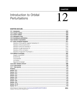
(AIAA, 2010). One of them is USSA76, the US Standard Atmosphere 1976 (NOAA/NASA/USAF,
1976). Figure 12.4 shows the US Standard Atmosphere density profile from the sea level to an altitude
of 1000 km. This figure was obtained by selecting the density ri at 28 altitudes zi in the USSA76
table and interpolating between them with the exponential functions rðzÞ ¼ rieðzziÞ=Hi
, where
656 CHAPTER 12 Introduction to Orbital Perturbations
7. FIGURE 12.4
US Standard Atmosphere 1976: density versus altitude.
zi z ziþ1 and Hi ¼ (ziþ1zi)/ln(riþ1/ri). The simple procedure is implemented in the MATLAB
function atmosphere.m, which is listed in Appendix D.41. For several equispaced altitudes (kilome-
ters), atmosphere yields the following densities (kilograms per cubic meter):
z [ logspace(0,3,6);
for i [ 1:6
altitude [ z(i);
density [ atmosphere(z(i));
fprintf(‘%12.3f km %12.3e kg/m
ˇ
3n’, altitude, density)
end
1.000 km 1.068e+00 kg/m
ˇ
3
3.981 km 7.106e-01 kg/m
ˇ
3
15.849 km 1.401e-01 kg/m
ˇ
3
63.096 km 2.059e-04 kg/m
ˇ
3
251.189 km 5.909e-11 kg/m
ˇ
3
1000.000 km 3.561e-15 kg/m
ˇ
3
According to USSA76, the atmosphere is a spherically symmetric 1000 km thick gaseous shell
surrounding the earth. Its properties throughout are steady state and are consistent with a period of
12.4 Atmospheric drag 657
8. moderate solar activity. The hypothetical variation of the properties with altitude approximately rep-
resents the year-round conditions at midlatitudes averaged over many years. The model provides realistic
values of atmospheric density which, however, may not match the actual values at a given place or time.
Drag affects the life of an orbiting spacecraft. Sputnik 1, the world’s first artificial satellite, had a
perigee altitude of 228 km, where the air density is about five orders of magnitude greater than at its
apogee altitude of 947 km. The drag force associated with repeated passage through the thicker air
eventually robbed the spherical, 80-kg Sputnik of the energy needed to stay in orbit. It fell from orbit
and burned up on January 4, 1958, almost 3 months to the day after it was launched by the Soviet Union.
Soon thereafter, on January 31, the United States launched its first satellite, the cylindrical, 14-kg
Explorer 1, into a 358 by 2550-km orbit. In this higher orbit, Explorer experienced less drag than
Sputnik, and it remained in orbit for 18 years. The International Space Station’s nearly circular orbit is
about 400 km above the earth. At that height, drag causes orbital decay that requires frequent reboosts,
usually provided by the propulsion systems of visiting supply vehicles. The altitude of the Hubble space
telescope’s circular orbit is 560 km, and it is also degraded by drag. Between 1993 and 2009, Space
Shuttle orbiters visited Hubble five times to service it and boost its orbit. With no propulsion system of
its own, the venerable Hubble is expected to deorbit around 2025, 35 years after it was launched.
If the inertial velocity of a spacecraft is v and that of the atmosphere at that point is vatm, then the
spacecraft velocity relative to the atmosphere is
vrel ¼ v vatm (12.8)
If the atmosphere rotates with the earth, whose angular velocity is uE, then relative to the origin O of
the geocentric equatorial frame, vatm ¼ uE r, where r is the spacecraft position vector. Thus,
vrel ¼ v uE r (12.9)
Since the drag force D on an object acts in the direction opposite to the relative velocity vector, we
can write
D ¼ D^
vrel (12.10)
where ^
vrel ¼ vrel=nrel is the unit vector in the direction of the relative velocity, and
D ¼
1
2
rv2
relCDA (12.11)
r is the atmospheric density, A is the frontal area of the spacecraft (the area normal to the relative
velocity vector), and CD is the dimensionless drag coefficient. If the mass of the spacecraft is m, then
the perturbing acceleration due to the drag force is p ¼ D/m, so that
p ¼
1
2
rvrel
CDA
m
vrel (12.12)
There apparently is no universal agreement on the name of the quantity in parentheses. We will call it
the ballistic coefficient,
B ¼
CDA
m
(12.13)
The reader may encounter alternative definitions of the ballistic coefficient, such as the reciprocal,
m/(CDA).
658 CHAPTER 12 Introduction to Orbital Perturbations
9. EXAMPLE 12.1
A small spherical earth satellite has a diameter of 1 m and a mass of 100 kg. At a given time t0, its orbital pa-
rameters are
Perigee radius: rp ¼ 6593 km ð215-km altitudeÞ
Apogee radius: ra ¼ 7317 km ð939-km altitudeÞ
Right ascension of the ascending node: U ¼ 340
Inclination: i ¼ 65:1
Argument of perigee: u ¼ 58
True anomaly: q ¼ 332
Assuming a drag coefficient of CD ¼ 2.2 and using the 1976 US Standard Atmosphere rotating with the earth,
employ Cowell’s method to find the time for the orbit to decay to 100 km. Recall from Eqn (2.67) that the angular
velocity of the earth is 72.9211 106
rad/s.
Solution
Let us first use the given data to compute some additional orbital parameters, recalling that m ¼ 398,600 km3
/s2
:
Eccentricity: e ¼
ra rp
ra þ rp
¼ 0:052049
Semimajor axis: a ¼
ra þ rp
2
¼ 6955 km
Angular momentum: h ¼
ffiffiffiffiffiffiffiffiffiffiffiffiffiffiffiffiffiffiffiffiffiffiffiffi
ma
1 e2
q
¼ 52;580:1 km2
=s
Period: T ¼
2p
ffiffiffi
m
p a
3
2 ¼ 96:207 min
Now we can use the six elements h, e, i, U, u, and q in Algorithm 4.5 to obtain the state vector (r0,v0) at the initial
time, relative to the geocentric equatorial frame,
r0 ¼ 5873:40^
I 658:522^
J þ 3007:49^
K ðkmÞ
v0 ¼ 2:89641^
I þ 4:09401^
J þ 6:14446^
K ðkm=sÞ
(a)
Referring to Section 1.8, we next write Eqn (12.2), which is a second-order differential equation in r, as two
first-order ordinary differential equations in r and _
rð¼ vÞ,
d
dt
r
v
¼
v
a
¼
8
:
v
m
r
r3
þ p
9
=
;
(b)
The drag acceleration p is given by Eqn (12.12) along with Eqn (12.9). With Eqn (a) as the initial conditions, we
can solve for r and v on the time interval [t0,tf] using, for example, MATLAB’s built-in numerical integrator ode45.
From the solution, we obtain the satellite’s altitude, which oscillates with time between the extreme values at
perigee and apogee. It is a simple matter to extract just the extrema and plot them, as shown in Figure 12.5 for
t0 ¼ 0 and tf ¼ 120 days. The orbit decays to 100 km in 108 days.
Observe that the apogee starts to decrease immediately, whereas the perigee remains nearly constant until the
very end. As the apogee approaches perigee, the eccentricity approaches zero. We say that atmospheric drag tends
to circularize an elliptical orbit.
The MATLAB script Example_12_01.m for this problem is located in Appendix D.42.
12.4 Atmospheric drag 659
10. 12.5 Gravitational perturbations
In Appendix E, it is shown that if the central attractor (e.g., the earth) is a sphere of radius R with a
spherically symmetric mass distribution, then its external gravitational potential field will be spheri-
cally symmetric, acting as though all of the mass were concentrated at the center O of the sphere. The
gravitational potential energy per unit mass (m ¼ 1 in Eqn (E.10)) is
V ¼
m
r
(12.14)
where m ¼ GM, G is the universal gravitational constant, M is the sphere’s mass, and r is the distance
from O to a point outside of the sphere (r R). Here r is the magnitude of the position vector r, which,
in Cartesian coordinates centered at O, is given by
r ¼ x^
i þ y^
j þ z^
k
Equipotential surfaces (those on which V is constant) are concentric spheres. The force on a unit mass
placed at r is the acceleration of gravity, which is given by a ¼ VV, where V is the gradient operator.
In Cartesian coordinates with the origin at O,
V [
v
vx
^
i þ
v
vy
^
j þ
v
vz
^
k
FIGURE 12.5
Perigee and apogee versus time.
660 CHAPTER 12 Introduction to Orbital Perturbations
11. Thus, a ¼ Vðm=rÞ, or
a ¼ m
vð1=rÞ
vx
^
i þ
vð1=rÞ
vy
^
j þ
vð1=rÞ
vz
^
k
¼
m
r2
vr
vx
^
i þ
vr
vy
^
j þ
vr
vz
^
k
But
r ¼
ffiffiffiffiffiffiffiffiffiffiffiffiffiffiffiffiffiffiffiffiffiffiffiffi
x2 þ y2 þ z2
p
(12.15)
from which we can easily show that
vr
vx
¼
x
r
vr
vy
¼
y
r
vr
vz
¼
z
r
(12.16)
Therefore, we have the familiar result (cf. Eqn (2.22))
a ¼ m
r
r3
(12.17)
As we first observed in Section 4.7, the earth and other spinning celestial bodies are not perfect
spheres. Many resemble oblate spheroids. For such a planet, the spin axis is the axis of rotational
symmetry of its gravitational field. Because of the equatorial bulge caused by centrifugal effects, the
gravitational field varies with the latitude as well as radius. This more complex gravitational potential
is dominated by the familiar point mass contribution given by Eqn (12.14) upon which is superimposed
the perturbation due to the oblateness.
It is convenient to use the spherical coordinate system shown in Figure 12.6. The origin O is at the
planet’s center of mass, and the z-axis of the associated Cartesian coordinate system is the axis of
rotational symmetry. (The rotational symmetry means that our discussion is independent of the choice
of Cartesian coordinate frame as long as each shares a common z-axis.) r is the distance of a point P
FIGURE 12.6
Spherical coordinate system.
12.5 Gravitational perturbations 661
12. from O, f is the polar angle measured from the positive z-axis to the radial, and q is the azimuth angle
measured from the positive x-axis to the projection of the radial onto the xy plane. Observe that
f ¼ tan1
ffiffiffiffiffiffiffiffiffiffiffiffiffiffiffi
x2 þ y2
p
z
(12.18)
Since the gravitational field is rotationally symmetric, it does not depend on the azimuth angle q.
Therefore, the gravitational potential may be written as
Vðr; fÞ ¼
m
r
þ Fðr; fÞ (12.19)
Here F is the perturbation of the gravitational potential due to the planet’s oblateness.
The rotationally symmetric perturbation Fðr; fÞ is given by the infinite series (Battin, 1999)
Fðr; fÞ ¼
m
r
X
N
k¼2
Jk
R
r
k
Pkðcos fÞ (12.20)
where Jk are the zonal harmonics of the planet, R is its equatorial radius (R/r 1), and Pk are the
Legendre polynomials (see below). The zonal harmonics are dimensionless numbers that are not
derived from mathematics but are inferred from observations of satellite motion around a planet, and
they are unique to that planet. The summation starts at k ¼ 2 instead of k ¼ 1 because J1 ¼ 0, due to the
fact that the origin of the spherical coordinate system is at the planet center of mass. For the earth, the
next six zonal harmonics are (Vallado, 2007)
J2 ¼ 0:00108263 J3 ¼ 2:33936 103J2
J4 ¼ 1:49601 103J2 J5 ¼ 0:20995 103J2
J6 ¼ 0:49941 103J2 J7 ¼ 0:32547 103J2
Earth zonal harmonics (12.21)
This set of zonal harmonics is clearly dominated by J2. For k 7 the zonal harmonics all remain more
than three orders of magnitude smaller than J2.
The Legendre polynomials are named after the French mathematician Adrien-Marie Legendre
(1752–1833). The polynomial Pk(x) may be obtained from a formula derived by another French
mathematician Olinde Rodrigues (1795–1851), as part of his 1816 doctoral thesis,
PkðxÞ ¼
1
2kk!
dk
dxk
x2
1
k
Rodrigues’ formula (12.22)
Using Rodrigues’ formula, we can calculate the first few of the Legendre polynomials that appear in
Eqn (12.20),
P2ðxÞ ¼ 1
2
3x2 1
P3ðxÞ ¼ 1
2
5x3 3x
P4ðxÞ ¼ 1
8
35x4 30x2 þ 3
P5ðxÞ ¼ 1
8
63x5 70x3 þ 15x
P6ðxÞ ¼ 1
16
231x6 315x4 þ 105x2 5
P7ðxÞ ¼ 1
16
429x7 693x5 þ 315x3 35x
(12.23)
662 CHAPTER 12 Introduction to Orbital Perturbations
13. FIGURE 12.7
Legendre polynomials P2 through P7.
These are plotted in Figure 12.7.
Since J2 is by far the largest zonal harmonic, we shall in the interest of simplicity focus only on its
contribution to the gravitational perturbation, thereby ignoring all but the J2 term in the series for
Fðr; fÞ. In that case, Eqn (12.20) yields
Fðr; fÞ ¼
J2
2
m
r
R
r
2
3 cos2
f 1
(12.24)
Observe that F ¼ 0 when cos f ¼
ffiffiffiffiffiffiffiffi
1=3
p
, which corresponds to about 35 geocentric latitude. This
band reflects the earth’s equatorial bulge (oblateness). The perturbing acceleration is the negative of
the gradient of F,
p ¼ VF ¼
vF
vx
^
i
vF
vy
^
j
vF
vz
^
k (12.25)
Noting that vF=vq ¼ 0, we have from the chain rule of calculus that
vF
vx
¼
vF
vr
vr
vx
þ
vF
vf
vf
vx
vF
vy
¼
vF
vr
vr
vy
þ
vF
vf
vf
vy
vF
vz
¼
vF
vr
vr
vz
þ
vF
vf
vf
vz
(12.26)
12.5 Gravitational perturbations 663
14. Differentiating Eqn (12.24), we obtain
vF
vr
¼
3
2
J2
m
r2
R
r
2
3 cos2
f 1
vF
vf
¼
3
2
J2
m
r
R
r
2
sin f cos f
(12.27)
Use Eqn (12.18) to find the required partial derivatives of f:
vf
vx
¼
xz
x2 þ y2 þ z2
1
ffiffiffiffiffiffiffiffiffiffiffiffiffiffiffi
x2 þ y2
p ¼
xz
r3sin f
vf
vy
¼
yz
x2 þ y2 þ z2
1
ffiffiffiffiffiffiffiffiffiffiffiffiffiffiffi
x2 þ y2
p ¼
yz
r3sin f
vf
vz
¼
ffiffiffiffiffiffiffiffiffiffiffiffiffiffiffi
x2 þ y2
p
x2 þ y2 þ z2
¼
sin f
r
(12.28)
Substituting Eqns (12.16), (12.27), and (12.28) into Eqn (12.26) and using the fact that cos f ¼ z=r
leads to the following expressions for the gradient of perturbing potential F:
vF
vx
¼
3
2
J2
m
r2
R
r
2
x
r
h
5
z
r
2
1
i
vF
vy
¼
3
2
J2
m
r2
R
r
2
y
r
h
5
z
r
2
1
i
vF
vz
¼
3
2
J2
m
r2
R
r
2
z
r
h
5
z
r
2
3
i
(12.29)
The perturbing gravitational acceleration p due to J2 is found by substituting these equations into Eqn
(12.25), yielding the vector
p ¼
3
2
J2mR2
r4
x
r
5
z2
r2
1
^
i þ
y
r
5
z2
r2
1
^
j þ
z
r
5
z2
r2
3
^
k
(12.30)
The perturbing accelerations for higher zonal harmonics may be evaluated in a similar fashion. Schaub
(2009, p. 553) lists the accelerations for J3 through J6.
Irregularities in the earth’s geometry and its mass distribution cause the gravitational field to vary
not only with latitude f but with longitude q as well. To mathematically account for this increased
physical complexity, the series expansion of the potential function F in Eqn (12.19) must be gener-
alized to include the azimuth angle q. As a consequence, it turns out that we can identify sectorial
harmonics, which account for the longitudinal variation over domains of the earth resembling seg-
ments of an orange. We also discover a tile-like patchwork of tesseral harmonics, which model how
664 CHAPTER 12 Introduction to Orbital Perturbations
15. specific regions of the earth deviate locally from a perfect, homogeneous sphere. Incorporating these
additional levels of detail into the gravitational model is essential for accurate long-term prediction of
satellite orbits (e.g., global positioning satellite constellations). For an in-depth treatment of this
subject, including the mathematical details, see Vallado (2007).
EXAMPLE 12.2
At time t ¼ 0, an earth satellite has the following orbital parameters:
Perigee radius: rp ¼ 6678 km ð300 km altitudeÞ
Apogee radius: ra ¼ 9940 km ð3062 km altitudeÞ
Right ascension of the ascending node: U ¼ 45
Inclination: i ¼ 28
Argument of perigee: u ¼ 30
True anomaly: q ¼ 40
Use Encke’s method to determine the effect of the J2 perturbation on the variation of right ascension of the node,
argument of perigee, angular momentum, eccentricity, and inclination over the next 48 hours.
Solution
Using Figure 2.18 along with Eqns (2.83), (2.84), and (2.71), we can find other orbital parameters in addition to
the ones given. In particular, recalling that m ¼ 398,600 km3
/s2
for the earth,
Eccentricity: e ¼
ra rp
ra þ rp
¼ 0:17136
Semimajor axis: a ¼
ra þ rp
2
¼ 8059 km
Period: T ¼
2p
ffiffiffi
m
p a
3
2 ¼ 7200 s ð120 minÞ
Angular momentum: h ¼
ffiffiffiffiffiffiffiffiffiffiffiffiffiffiffiffiffiffiffiffiffiffiffiffi
ma
1 e2
q
¼ 55;839 km2
=s
The six elements h, e, i, U, u, and q together with Algorithm 4.5 yield the state vector (r0,v0) at the initial time,
relative to the geocentric equatorial frame,
r0 ¼ 2384:46^
I þ 5729:01^
J þ 3050:46^
K ðkmÞ
v0 ¼ 7:36138^
I 2:98997^
J þ 1:64354^
K ðkm=sÞ
(a)
Using this state vector as a starting point, with t0 ¼ 0, tf ¼ 48 3600 s, and Dt ¼ (tf t0)/1000, we enter the
Encke procedure (Algorithm 12.1) with MATLAB’s ode45 as the numerical integrator to find r and v at each of the
1001 equally spaced times. At these times, we then use Algorithm 4.2 to compute the right ascension of the node
and the argument of perigee, which are plotted in Figure 12.8.
Figure 12.8 shows that the J2 perturbation causes a drift in both U and u over time. For this particular orbit, U
decreases whereas u increases. We see that both parameters have a straight line or secular variation upon which a
small or short periodic variation is superimposed. Approximate average values of the slopes of the curves for U
and u are most simply found by dividing the difference between the computed values at tf and t0 by the time span
tf t0. In this way, we find that
_
U ¼ 0:172 deg=h (b)
_
u ¼ 0:282 deg=h (c)
12.5 Gravitational perturbations 665
16. As pointed out in Section 4.7, the decrease in the node angle U with time is called regression of the node, whereas
the increase of argument of perigee u with time is called the advance of perigee.
The computed time histories of h, e, and i are shown in Figure 12.9. Clearly, none of these osculating elements
shows a secular variation due to the earth’s oblateness. They are all constant except for the short periodic per-
turbations evident in all three plots.
The MATLAB script Example_12_02.m for this problem is in Appendix D.43.
Theresultsobtainedintheabove examplefollowfromthe specificinitialconditionsthatwe suppliedto
the Encke numerical integration procedure. We cannot generalize the conclusions of this special pertur-
bation analysis to other orbits. In fact, whether or not the node line and the eccentricity vector advances or
regressesdependsonthenatureoftheparticularorbit.We canconfirmthisbymeansofrepeatednumerical
analyses with different initial conditions. Obtaining formulas that describe perturbation phenomena for
general cases is the object of general perturbation analysis, which is beyond the scope of this book.
FIGURE 12.8
Histories of the right ascension of the ascending node and the argument of perigee for a time span of 48 h. The
plotted points were obtained using Encke’s method.
666 CHAPTER 12 Introduction to Orbital Perturbations
17. FIGURE 12.9
Histories the J2 perturbed angular momentum, eccentricity, and inclination for a time span of 48 h.
However, a step in that direction is to derive expressions for the timevariations of the osculating elements.
These are the Lagrange planetary equations or their variant, the Gauss variational equations. Both are
based on the variation of parameters approach to solving differential equations.
12.6 Variation of parameters
For the two-body problem, the equation of motion (Eqn (2.22))
€
r þ m
r
r3
¼ 0 (12.31)
yields the position vector r as a function of time t and six parameters or orbital elements c,
r ¼ fðc; tÞ (12.32)
where c stands for the set of six parameters (c1, c2, ., c6). Keep in mind that the vector f has three
scalar components.
12.6 Variation of parameters 667
18. EXAMPLE 12.3
At time t0, the state vector of a spacecraft in two-body motion is P r0 v0 R. What is f(c,t) in this case?
Solution
The constant orbital elements c are the six components of the state vector,
c ¼ P r0 v0 R
By means of Algorithm 3.4, we find
r ¼ fðtÞr0 þ gðtÞv0 (a)
where the time-dependent Lagrange f and g functions are given by Eqn (3.69) (Examples 3.7 and 4.2). Thus,
fðc; tÞ ¼ fðtÞr0 þ gðtÞv0
As we know from Section 4.4, the orbital parameters that may alternatively be selected as the
classical elements at time t0, are the longitude of the node U, inclination i, argument of periapse u,
eccentricity e, angular momentum h (or semimajor axis a), and true anomaly q (or the mean anomaly
M, or the eccentric anomaly E). For t t0, only the anomalies vary with time, a fact that is reflected by
the presence of the argument t in f(c,t) above. As pointed out in Section 3.2, we could use time of
periapse passage tp as the sixth orbital parameter instead of true anomaly. The advantage of doing so in
the present context would be that tp is a constant for Keplerian orbits. (Up to now we have usually set
that constant equal to zero.)
The velocity v is the time derivative of the position vector r, so that from Eqn (12.32),
v ¼
d
dt
fðc; tÞ ¼
v
vt
fðc; tÞ þ
X
6
a¼1
v
vca
fðc; tÞ
dca
dt
(12.33)
Since the orbital elements are constant in two-body motion, their time derivatives are zero,
dca
dt
¼ 0 a ¼ 1; .; 6
Therefore, Eqn (12.33) becomes simply
v ¼
v
vt
fðc; tÞ Two-body motion (12.34)
We find the acceleration by taking the time derivative of v in Eqn (12.34) while holding c constant,
a ¼
v2
vt2
fðc; tÞ Two-body motion
Substituting this and Eqn (12.32) into Eqn (12.31) yields
v2
vt2
fðc; tÞ þ m
fðc; tÞ
kfðc; tÞk3
¼ 0 (12.35)
668 CHAPTER 12 Introduction to Orbital Perturbations
19. A perturbing force produces a perturbing acceleration p that results in a perturbed motion rp for
which the equation of motion is
€
rp þ m
rp
r3
p
¼ p (12.36)
The variation of parameters method requires that the solution to Eqn (12.36) have the same mathe-
matical form f as it does for the two-body problem, except that the six constants c in Eqn (12.32) are
replaced by six functions of time u(t), so that
rp ¼ fðuðtÞ; tÞ (12.37)
where u(t) stands for the set of six functions u1(t),u2(t), . ,u6(t). The six parameters u(t) are the orbital
elements of the osculating orbit that is tangent to rp at time t.
We find the velocity vector vp for the perturbed motion by differentiating Eqn (12.37) with respect
to time and using the chain rule,
vp ¼
drp
dt
¼
vfðu; tÞ
vt
þ
X
6
b¼1
vfðu; tÞ
vub
dub
dt
(12.38)
In order for vp to have the same mathematical form as v for the unperturbed case (Eqn (12.34)), we
impose the following three conditions on the osculating elements u(t):
X
6
b¼1
vfðu; tÞ
vub
dub
dt
¼ 0 (12.39)
Eqn (12.38) therefore becomes simply
vp ¼
vfðu; tÞ
vt
(12.40)
To find €
rp, the acceleration of the perturbed motion, we differentiate the velocity vp with respect to
time. It follows from Eqn (12.40) that
€
rp ¼
dvp
dt
¼
v2
fðu; tÞ
vt2
þ
X
6
b¼1
v2
fðu; tÞ
vubvt
dub
dt
(12.41)
Substituting Eqns (12.37) and (12.41) into Eqn (12.36) yields
v2
fðu; tÞ
vt2
þ
X
6
b¼1
v2
fðu; tÞ
vubvt
dub
dt
þ m
fðu; tÞ
kfðu; tÞk3
¼ p (12.42)
But
v2
fðu; tÞ
vt2
þ m
fðu; tÞ
kfðu; tÞk3
¼ 0 (12.43)
12.6 Variation of parameters 669
20. because the six osculating orbital elements u evaluated at any instant of time define a Keplerian orbit
for which Eqn (12.31) is valid. That means Eqn (12.42) reduces to
X
6
b¼1
v2
fðu; tÞ
vubvt
dub
dt
¼ p (12.44)
These are three conditions on the six functions u(t) in addition to the three conditions listed above in
Eqn (12.39). If we simplify our notation by letting r ¼ f(u,t) and v ¼ vfðu; tÞ=vt, then the six Eqns
(12.39) and (12.44), respectively, become
X
6
b¼1
vr
vub
dub
dt
¼ 0 (12.45a)
X
6
b¼1
vv
vub
dub
dt
¼ p (12.45b)
These are the six osculating conditions imposed by the variation of parameters to ensure that the
osculating orbit at each point of a perturbed trajectory is Keplerian (two-body) in nature.
In matrix form, Eqns (12.45) may be written as
½Lf_
ug ¼ fPg (12.46a)
where
½L ¼
vxi=vua
vvi=vua
#
f_
ug ¼ f _
uag fPg ¼
8
:
0
pi
9
=
;
i ¼ 1; 2; 3
a ¼ 1; 2; .; 6
(12.46b)
[L] is the 6 by 6 Lagrangian matrix. x1, x2, and x3 are the xyz components of the position vector r in a
Cartesian inertial reference. Likewise, v1, v2, and v3 are the inertial velocity components, whereas p1,
p2, and p3 are the xyz components of the perturbating acceleration. The solution of Eqn (12.46) yields
the time variations of the osculating elements
f_
ug ¼ ½L1
fPg (12.47)
An alternate straightforward manipulation of Eqns (12.45) reveals that the Lagrange matrix [L] and the
acceleration vector {P} may be written as
½L ¼
X
3
i¼1
vxi
vua
vvi
vub
vvi
vua
vxi
vub
#
fPg ¼
(
X
3
i¼1
pi
vxi
vua
)
a; b ¼ 1; 2; .; 6 (12.48)
These are the forms attributable to Lagrange, and in that case Eqn (12.48) are known as
the Lagrange planetary equations. If the perturbing forces, and hence the perturbing
670 CHAPTER 12 Introduction to Orbital Perturbations
21. accelerations, are conservative, like gravity, then p is the spatial gradient of a scalar potential
function R, that is,
pi ¼
vR
vxi
i ¼ 1; 2; 3
It follows from Eqn (12.48) that {P} is the gradient of a function of the orbital elements,
fPg ¼
(
X
3
i¼1
vR
vxi
vxi
vua
)
¼
vR
vua
a ¼ 1; 2; .; 6 (12.49)
The Lagrange planetary equations for the variation of the six classical orbital elements a, e, tp, U, i, and
u, as derived by Battin (1999) and others, may be written as follows:
da
dt
¼
2a2
m
vR
vtp
(12.50a)
de
dt
¼
ffiffiffiffiffiffiffiffiffiffiffiffiffi
1 e2
p
ffiffiffiffiffiffi
ma
p
e
vR
vu
a
1 e2
me
vR
vtp
(12.50b)
dtp
dt
¼
2a2
m
vR
va
þ
a
1 e2
me
vR
ve
(12.50c)
dU
dt
¼
1
ffiffiffiffiffiffiffiffiffiffiffiffiffiffiffiffiffiffiffiffiffiffi
mað1 e2Þ
p
sin i
vR
vi
(12.50d)
di
dt
¼
1
ffiffiffiffiffiffiffiffiffiffiffiffiffiffiffiffiffiffiffiffiffiffi
mað1 e2Þ
p
1
tan i
vR
vu
1
sin i
vR
vU
(12.50e)
du
dt
¼
1
ffiffiffiffiffiffiffiffiffiffiffiffiffiffiffiffiffiffiffiffiffiffi
mað1 e2Þ
p
tan i
vR
vi
þ
ffiffiffiffiffiffiffiffiffiffiffiffiffi
1 e2
p
ffiffiffiffiffiffi
ma
p
e
vR
ve
(12.50f)
The Lagrange planetary equations were obtained by writing the state vector components r and v in
terms of the orbital parameters u, then taking partial derivatives to form the Lagrangian matrix [L], and
finally inverting [L] to find the time variations of u, as in Eqn (12.50). The more direct Gauss approach
is to obtain the orbital elements u from the state vector, as in Algorithm 4.2, and then differentiate
those expressions with respect to time to get the equations of variation. Gauss’s form of the Lagrange
planetary equations relaxes the requirement for perturbations to be conservative and avoids the lengthy
though systematic procedure devised by Lagrange for computing the Lagrange matrix [L] in Eqn
(12.48). We will pursue the Gauss approach in the next section.
12.7 Gauss variational equations
Let u be an osculating element. Its time derivative is
du
dt
¼
vu
vr
$
dr
dt
þ
vu
vv
$
dv
dt
(12.51)
12.7 Gauss variational equations 671
22. The acceleration dv/dt consists of the two-body part plus that due to the perturbation,
dv
dt
¼ m
r
r3
þ p (12.52)
Therefore, Eqn (12.51) becomes
du
dt
¼
vu
vr
dr
dt
þ
vu
vv
m
r
r3
þ
vu
vv
$p
or
du
dt
¼
du
dt
two-body
þ
vu
vv
$p (12.53)
Except for the true, mean, and eccentric anomalies, the Keplerian elements are constant, so that
du/dt)two-body ¼ 0, whereas
dq
dt
two-body
¼
h
r2
(12.54)
dM
dt
two-body
¼ n (12.55)
dE
dt
two-body
¼
na
r
(12.56)
We usually do orbital mechanics and define the orbital elements relative to a Cartesian inertial
frame with origin at the center of the primary attractor. For earth-centered missions, we have employed
the geocentric equatorial frame extensively throughout this book. Although not necessary, it may be
convenient to imagine it as our inertial frame in what follows. The orthogonal unit vectors of the
inertial frame are ^
I, ^
J, and ^
K. As illustrated in Figure 4.7, they form a right-hand triad, so that
^
K ¼ ^
I ^
J.
Another Cartesian inertial reference that we have employed for motion around a central attractor is
the perifocal frame illustrated in Figure 2.29. The orthogonal unit vectors along its x-, y-, and z-axes are
^
p, ^
q, and ^
w, respectively. The unit vector ^
p (not to be confused with the perturbing acceleration p) lies
in the direction of the eccentricity vector of the orbiting body, ^
w is normal to the orbital plane, and ^
q
completes the right-handed triad: ^
w ¼ ^
p ^
q. Equation (4.48), repeated here, gives the direction cosine
matrix for the transformation from XYZ to pqw:
½QX
x¼
2
4
sin U cos i sin u þ cos U cos u cos U cos i sin u þ sin U cos u sin i sin u
sin U cos i cos u cos U sin u cos U cos i cos u sin U sin u sin i cos u
sin U sin i cos U sin i cos i
3
7
7
5 (12.57)
U, u, and i are, respectively, the right ascension, argument of periapsis, and inclination.
We have also made use of noninertial LVLH frames in connection with the analysis of relative
motion (see Figure 7.1). It will be convenient to use such a reference for the perturbation analysis in this
672 CHAPTER 12 Introduction to Orbital Perturbations
23. section. The orthogonal unit vectors of this frame are ^
r, ^
s, and ^
w. ^
r is directed radially outward from the
central attractor to the orbiting body and defines the direction of the local vertical. As in the perifocal
frame, ^
w is the unit vector normal to the osculating orbital plane of the orbiting body. ^
w lies in the
direction of the angular momentum vector h, so that ^
w ¼ h=h. The transverse unit vector ^
s (which we
have previously denoted ^
ut) is normal to both ^
r and ^
w, and it therefore points in the direction of the
orbiting body’s local horizon: ^
s ¼ ^
w ^
r. The rsw and pqr frames are illustrated in Figure 12.10.
The transformation from pqw to rsw is simply a rotation about the normal ^
w through the true
anomaly q. According to Eqn (4.34), the direction cosine matrix for this rotation is
½R3ðqÞ ¼
2
6
6
4
cos q sin q 0
sin q cos q 0
0 0 1
3
7
7
5
Therefore, the transformation from XYZ to rsw is represented by ½QXr ¼ ½R3ðqÞ½QXx. Carrying out
the matrix multiplication and using the trig identities sinðu þ qÞ ¼ sin u cos q þ cos u sin q and
cosðu þ qÞ ¼ cos u cos q sin u sin q leads to
½QXr ¼
2
6
6
4
sin U cos i sin u þ cos U cos u cos U cos i sin u þ sin U cos u sin i sin u
sin U cos i cos u cos U sin u cos U cos i cos u sin U sin u sin i cos u
sin U sini cos U sin i cos i
3
7
7
5 (12.58)
where u ¼ u þ q. u is known as the argument of latitude. The direction cosine matrix [Q]Xr could of
course be obtained from Eqn (12.57) by simply replacing the argument of periapsis u with the
argument of latitude u.
FIGURE 12.10
The perifocal pqw frame and the local vertical–local horizon rsw frame. u is the argument of latitude.
12.7 Gauss variational equations 673
24. In terms of its components in the inertial XYZ frame, the perturbing acceleration p is expressed
analytically as follows:
p ¼ pX
^
I þ pY
^
J þ pZ
^
K (12.59)
whereas in the noninertial rsw frame
p ¼ pr^
r þ ps^
s þ pw ^
w (12.60)
The transformation between these two sets of components is
8
:
pr
ps
pw
9
=
;
¼ ½QXr
8
:
pX
pY
pZ
9
=
;
(12.61)
and
8
:
pX
pY
pZ
9
=
;
¼ ½QT
Xr
8
:
pr
ps
pw
9
=
;
(12.62)
½QT
Xr is the transpose of the direction cosine matrix in Eqn (12.58).
Each row of [Q]Xr comprises the direction cosines of the unit vectors ^
r, ^
s, and ^
w, respectively,
relative to the XYZ axes. Therefore, from Eqn (12.58), it is apparent that
^
r ¼ ð sin U cos i sin u þ cos U cos uÞ^
I þ ðcos U cos i sin u þ sin U cos uÞ^
J þ sin i sin u^
K (12.63a)
^
s ¼ ð sin U cos i cos u cos U sin uÞ^
I þ ðcos U cos i cos u sin U sin uÞ^
J þ sin i cos u^
K (12.63b)
^
w ¼ sin U sin i^
I cos U sin i^
J þ cos i^
K (12.63c)
These will prove useful in the following derivation of the time derivatives of the osculating orbital
elements h, e, q, U, i, and u. The formulas that we obtain for these derivatives will be our version of the
Gauss planetary equations.
We will employ familiar orbital mechanics formulas from Chapters 1, 2, and 4 to find the time
derivatives that we need. The procedure involves the use of basic differential calculus, some vector
operations, and a lot of algebra. Those who prefer not to read through the derivations can skip to the
summary listing of the Gauss planetary equations in Eqn (12.84).
Variation of the specific angular momentum h
The time derivative of the angular momentum h ¼ r v due to the perturbing acceleration p is
dh
dt
¼
dr
dt
v þ r
dv
dt
¼ v v þ r m
r
r3
þ p
674 CHAPTER 12 Introduction to Orbital Perturbations
25. But v v ¼ r r ¼ 0, so this becomes
dh
dt
¼ r p (12.64)
Since the magnitude of the angular momentum is h ¼
ffiffiffiffiffiffiffiffi
h$h
p
, its time derivative is
dh
dt
¼
d
dt
ffiffiffiffiffiffiffiffi
h$h
p
¼
1
2
1
ffiffiffiffiffiffiffiffi
h$h
p
2h$
dh
dt
¼
h
h
$
dh
dt
¼ ^
w$
dh
dt
Substituting Eqn (12.64) yields
dh
dt
¼ ^
w$ðr pÞ (12.65)
Using the vector identity in Eqn (1.21) (interchange of the dot and the cross), we can modify this to
read
dh
dt
¼ ð^
w rÞ$p
Since r ¼ r^
r and ^
w ^
r ¼ ^
s, it follows that
dh
dt
¼ rps (12.66)
where ps ¼ p$^
s. Clearly, the variation of the angular momentum depends only on perturbation
components that lie in the transverse (local horizon) direction.
Variation of the eccentricity e
The eccentricity may be found from Eqn (4.11),
e ¼
ffiffiffiffiffiffiffiffiffiffiffiffiffiffiffiffiffiffiffiffiffiffiffiffiffiffiffiffiffiffiffiffiffiffiffiffiffi
1 þ
h2
m2
v2
2m
r
s
(12.67)
To find its time derivative, we will use Eqn (12.53),
de
dt
¼
ve
vv
$p (12.68)
since de/dt)two-body ¼ 0. Differentiating Eqn (12.67) with respect to v and using vv2=vv ¼ 2v together
with vh2=vv ¼ 2h r yields
ve
vv
¼
1
2e
v
vv
h2
m2
v2
2m
r
¼
1
m2e
h2
v þ
v2
2m
r
ðh rÞ
12.7 Gauss variational equations 675
26. Substituting v ¼ vr^
r þ vs^
s and h r ¼ h^
w r^
r ¼ hr^
s we get
ve
vv
¼
1
m2e
h2
vr^
r þ
hr
v2
2m
r
þ h2
vs
^
s
Keeping in mind that vs is the same as vt, we can use Eqn (2.31) (vs ¼ h/r) along with Eqn (2.49)
(vr ¼ me sin q/h) to write this as
ve
vv
¼
h
m
sin q^
r þ
h
m2e
r
v2
2m
r
þ
h2
r
^
s (12.69)
According to Problem 2.10, v ¼ ðm=hÞ
ffiffiffiffiffiffiffiffiffiffiffiffiffiffiffiffiffiffiffiffiffiffiffiffiffiffiffiffiffiffiffiffiffiffi
1 þ 2e cos q þ e2
p
. Using the orbit formula (Eqn (2.45)) in the
form e cos q ¼ ðh2=mrÞ 1, we can write this as v ¼
ffiffiffiffiffiffiffiffiffiffiffiffiffiffiffiffiffiffiffiffiffiffiffiffiffiffiffiffiffiffiffiffiffiffiffiffiffiffiffiffiffiffiffiffi
2m=r m2ð1 e2Þ=h2
p
and substitute it into
Eqn (12.69) to get
ve
vv
¼
h
m
sin q^
r þ
1
mh
h2
þ mr
cos q þ mer
^
s
Finally, it follows from Eqn (12.68) that
de
dt
¼
h
m
sin qpr þ
1
mh
h2
þ mr
cos q þ mer
ps (12.70)
where pr ¼ p$^
r and ps ¼ p$^
s. Clearly, the eccentricity is affected only by perturbations that lie in the
orbital plane.
Variation of the true anomaly q
According to Eqns (12.53) and (12.54),
dq
dt
¼
h
r2
þ
vq
vv
$p (12.71)
To find vq=vv, we start with the orbit formula (Eqn (2.45)), writing it as
mer ¼
h2 mr
cos q
(12.72)
Another basic equation containing the true anomaly is the radial speed formula (Eqn (2.49)), from
which we obtain
mer ¼
hr$v
sin q
(12.73)
Equating these two expressions for mer yields
h2
mr
sin q ¼ hðr$vÞcos q
676 CHAPTER 12 Introduction to Orbital Perturbations
27. Applying the partial derivative with respect to v and rearranging the terms leads to
h2
mr
cos q þ hðr$vÞsin q
vq
vv
¼ h
vðr$vÞ
vv
cos q þ ½ðr$vÞcos q 2hsin q
vh
vv
The use of Eqns (12.72) and (12.73) simplifies the square brackets on each side, so that
mer
vq
vv
¼ h
vðr$vÞ
vv
cos q
h2
þ mr
sin q
h
vh
vv
Making use of vðr$vÞ=vv ¼ r and vh=vv ¼ ðh rÞ=h yields
vq
vv
¼
h
me
cos q^
r
1
e
h2
m
þ r
sin q
h
^
s (12.74)
where it is to be recalled that ^
s ¼ ^
w ^
r. Substituting this expression for vq=vv into Eqn (12.71) finally
yields the time variation of true anomaly,
dq
dt
¼
h
r2
þ
1
eh
h2
m
cos qpr
h2
m
þ r
sin qps
(12.75)
Like the eccentricity, true anomaly is unaffected by perturbations that are normal to the orbital plane.
Variation of right ascension U
As we know, and as can be seen from Figure 12.10, the right ascension of the ascending node is the
angle between the inertial X-axis and the node line vector N. Therefore, it may be found by using the
vector dot product,
cos U ¼
N
ffiffiffiffiffiffiffiffiffiffi
N$N
p $^
I
We employed this formula in Algorithm 4.2. Alternatively, it should be evident from Figure 12.11 that
we can use the equation tan U ¼ hX=hY . Since hX ¼ h$^
I and hY ¼ h$^
J, this can be written as
tan U ¼
h$^
I
h$^
J
(12.76)
The time derivative of Eqn (12.76) is
1
cos2 U
dU
dt
¼
h$^
J
dh
dt
$^
I
h$^
I
dh
dt
$^
J
h$^
J
2
¼
hY
dh
dt
$^
I
hX
dh
dt
$^
J
hY
2
or, more simply,
dU
dt
¼ cos2
U
dh
dt
$
hX
^
J hY
^
I
hY
2
(12.77)
12.7 Gauss variational equations 677
28. FIGURE 12.11
Relation between the components of angular momentum and the node angle U.
Since h ¼ h^
w and ^
w is given by Eqn (12.63c), we have
h ¼ h sin U sin i^
I h cos U sin i^
J þ h cos i^
K
This shows that hX ¼ hsin Usin i and hY ¼ hcos Usin i, so that Eqn (12.77) becomes
dU
dt
¼
dh
dt
$
h sin i cos U^
I þ sin U^
J
ðh sin iÞ2
¼
1
h sin i
^
N$
dh
dt
in which ^
N is the unit vector along the node line. Recalling that dh/dt ¼ r p yields
dU
dt
¼
1
h sin i
^
N$ðr pÞ ¼
1
h sin i
^
N r $p (12.78)
where we interchanged the dot and the cross by means of the identity in Eqn (1.21). The angle between
the node line ^
N and the radial r is the argument of latitude u, and since ^
w is normal to the plane of ^
N
and r, it follows from the definition of the cross product operation that ^
N r ¼ rsin u^
w. Therefore,
Eqn (12.78) may be written as
dU
dt
¼
rsin u
hsin i
^
w$p (12.79)
or, since ^
w$p ¼ pw,
dU
dt
¼
rsin u
hsin i
pw (12.80)
678 CHAPTER 12 Introduction to Orbital Perturbations
29. Clearly, the variation of right ascension U is influenced only by perturbations that are normal to the
orbital plane.
Variation of the inclination i
The orbital inclination, which is the angle i between the Z-axis and the normal to the orbital plane
(Figure 12.10), may be found from Eqn (4.7),
cos i ¼
h$^
K
h
Differentiating this expression with respect to time yields
di
dt
sin i ¼
1
h
dh
dt
$^
K
1
h2
dh
dt
h$^
K
Using Eqns (12.64) and (12.65), along with h$^
K ¼ h cos i, we find that
di
dt
sin i ¼
r
h
^
w cos i ^
K $ð^
r pÞ
Replacing ^
w by the expression in Eqn (12.63c) yields
di
dt
¼
r
h
sin U cos i^
I cos U cos i^
J sin i^
K $ð^
r pÞ
¼
r
h
h
sin U cos i^
I cos U cos i^
J sin i^
K ^
r
i
$p
where we once again used Eqn (1.21) to interchange the dot and the cross. Replacing the unit vector ^
r
by Eqn (12.63a) and using the familiar determinant formula for the cross product, we get
di
dt
¼
r
h
^
I ^
J ^
K
sin U cos i cos U cos i sin i
sin U cos i sin u þ cos U cos u cos U cos i sin u þ sin U cos u sin i sin u
$p
Expanding the determinant and recognizing ^
w from Eqn (12.63c), we find
di
dt
¼
r
h
cos u sin U sin i^
I cos U sin i^
J þ cos i^
K $p ¼
r
h
cos uð^
w$pÞ
Since ^
w$p ¼ pw,
di
dt
¼
r
h
cos u pw (12.81)
Like U, the orbital inclination is affected only by perturbation components that are normal to the
orbital plane.
12.7 Gauss variational equations 679
30. Variation of argument of periapsis u
The arguments of periapsis and latitude are related by u ¼ u q. Let us first seek an expression for
du/dt and then obtain the variation du/dt from the fact that du/dt ¼ du/dt dq/dt, where we found
dq/dt above in Eqn (12.74).
Since the argument of latitude is the angle u between the node line vector N and the position vector
r, it is true that cos u ¼ ^
r$^
N. Differentiating this expression with respect to the velocity vector v and
noting that ^
N ¼ cos U^
I þ sin U^
J, we get
vu
vv
¼
1
sin u
^
r$
v^
N
vv
¼
1
sin u
sin U^
r$^
I cos U^
r$^
J
vU
vv
Using the expression for the radial unit vector ^
r in Eqn (12.63a), we conclude that
sin U^
r$^
I cos U^
r$^
J ¼ cos i sin u
which simplifies our result,
vu
vv
¼ cos i
vU
vv
(12.82)
From Eqn (12.53), we know that dU=dt ¼ ðvU=vvÞ$p, whereas according to Eqn (12.79),
dU=dt ¼ ðr sin u=h sin iÞ^
w$p. It follows that
vU
vv
¼
r sin u
h sin i
^
w
Therefore, Eqn (12.82) yields
vu
vv
¼
r sin u
h tan i
^
w
Finally, since du=dt ¼ ðvu=vvÞ$p, we conclude that
du
dt
¼
rsin u
htan i
pw
Substituting this result into du/dt ¼ du/dt dq/dt and making use of Eqn (12.74) (the variation of q due
solely to perturbations) yields
du
dt
¼
1
eh
h2
m
cos qpr
r þ
h2
m
sin qps
r sinðu þ qÞ
h tan i
pw (12.83)
We see that du/dt depends on all three components of the perturbing acceleration.
For convenience, let us summarize the Gauss form of the planetary equations that govern the
variations of the orbital elements angular momentum h, eccentricity e, true anomaly q, node angle U,
inclination i, and argument of periapsis u.
dh
dt
¼ rps (12.84a)
680 CHAPTER 12 Introduction to Orbital Perturbations
31. de
dt
¼
h
m
sin qpr þ
1
mh
h2
þ mr
cos q þ mer
ps (12.84b)
dq
dt
¼
h
r2
þ
1
eh
h2
m
cos qpr
r þ
h2
m
sin qps
(12.84c)
dU
dt
¼
r
h sin i
sinðu þ qÞpw (12.84d)
di
dt
¼
r
h
cosðu þ qÞpw (12.84e)
du
dt
¼
1
eh
h2
m
cos qpr
r þ
h2
m
sin qps
r sinðu þ qÞ
h tan i
pw (12.84f)
where r ¼ h2=½mð1 þ e cos qÞ (Eqn (2.45)).
Given the six orbital elements h0, e0, q0, U0, i0, and u0 at time t0 and the functional form of the
perturbing acceleration p, we can numerically integrate the six planetary equations to obtain the
osculating orbital elements and therefore the state vector at subsequent times. Formulas for the var-
iations of alternative orbital elements can be derived, but it is not necessary here because at any instant
all other osculating orbital parameters are found in terms of the six listed above. For example,
Semimajor axis
Eqn 2:72
: a ¼
h2
m
1
1 e2
Eccentric anomaly
Eqn 3:13
: E ¼ 2 tan1
ffiffiffiffiffiffiffiffiffiffiffi
1 e
1 þ e
r
tan
q
2
!
Mean anomaly
Eqn 3:6
: M ¼ 2 tan1
ffiffiffiffiffiffiffiffiffiffiffi
1 e
1 þ e
r
tan
q
2
!
e
ffiffiffiffiffiffiffiffiffiffiffiffiffi
1 e2
p
sin q
1 þ e cos
EXAMPLE 12.4
Obtain the form of the Gauss planetary equations for a perturbing force that is tangent to the orbit.
Solution
If the perturbing force is tangent to the orbit, then the perturbing acceleration p lies in the direction of the velocity
vector v,
p ¼ pv
v
v
The radial and transverse components of the perturbing acceleration are found by projecting p onto the radial and
transverse directions
pr ¼
pv
v
v
$^
r ¼
pv
v
ðv$^
rÞ ¼
pv
v
vr
ps ¼
pv
v
v
$^
s ¼
pv
v
ðv$^
sÞ ¼
pv
v
vs
12.7 Gauss variational equations 681
32. The component pw normal to the orbital plane is zero. From Eqns (2.31) and (2.49), we have
vs ¼
h
r
vr ¼
m
h
e sin q
Therefore, for a tangential perturbation, the rsw components of acceleration are
pr ¼
m
vh
epv sin q
ps ¼
h
vr
pv
pw ¼ 0
Substituting these expressions into Eqn (12.84) leads to the Gauss planetary equations for tangential
perturbations,
dh
dt
¼
h
v
pv
de
dt
¼
2
v
ðe þ cos qÞpv
dq
dt
¼
h
r2
2
ev
pv sin q
dU
dt
¼ 0
di
dt
¼ 0
du
dt
¼
2
ev
pv sin q
Tangential perturbation (12.85)
Clearly, the right ascension and the inclination are unaffected.
If the perturbing acceleration is due to a tangential thrust T, then pv ¼ T/m, where m is the instan-
taneous mass of the spacecraft. If the thrust is in the direction of the velocity v, then pv is positive and
tends to speed up the spacecraft, producing an outwardly spiraling trajectory like that shown in
Figure 12.1. According to Eqn (12.85), a positive tangential acceleration causes the eccentricity to
increase and the perigee to advance (rotating the apse line counterclockwise). Both of these effects are
evident in Figure 12.1. If the thrust is opposite to the direction of v, then the effects are opposite: the
spacecraft slows down, spiraling inward.
Atmospheric drag acts opposite to the direction of motion. If we neglect the rotation of the at-
mosphere, then according to Eqn (12.12), the tangential acceleration is
pv ¼
1
2
rv2
B (12.86)
in which v is the inertial speed and B is the ballistic coefficient. Substituting this expression into Eqn
(12.85) yields the Gauss planetary equations for atmospheric drag,
dh
dt
¼
B
2
hrv
de
dt
¼ Bðe þ cos qÞrv
dq
dt
¼
h
r2
þ B
rv
e
sin q
dU
dt
¼ 0
di
dt
¼ 0
du
dt
¼ B
rv
e
sin q
(12.87)
682 CHAPTER 12 Introduction to Orbital Perturbations
33. EXAMPLE 12.5
Find the components pr, ps, and pw of the gravitational perturbation of Eqn (12.30) in the rsw frame of Figure 12.10.
Solution
The transformation from XYZ to rsw is given by Eqn (12.61). Using the direction cosine matrix in Eqn (12.58) we
therefore have
8
:
pr
ps
pw
9
=
;
¼
3
2
J2mR2
r4
2
6
6
6
4
sin U cos i sin u þ cos U cos u cos U cos i sin u þ sin U cos u sin i sin u
sin U cos i cos u cos U sin u cos U cos i cos u sin U sin u sin i cos u
sin U sin i cos U sin i cos i
3
7
7
7
5
$
8
:
X
r
5
Z2
r2
1
Y
r
5
Z2
r2
1
Z
r
5
Z2
r2
3
9
=
;
(a)
Before carrying out the multiplication, note that in the spherical coordinate system of Figure 12.12,
Z ¼ r sin d
X ¼ r cos d cos a
Y ¼ r cos d sin a
(b)
FIGURE 12.12
Spherical coordinates and the geocentric equatorial frame.
12.7 Gauss variational equations 683
34. Here a is the azimuth angle measured in the XY plane positive from the X-axis. (We use a instead of the traditional q to
avoid confusion with true anomaly.) The declination d is the complement of the usual polar angle f, which is measured
positive from the polar (Z) axis toward the equator. As shown in Figure 12.6, d is measured positive northward from the
equator. Using d instead of f makes it easier to take advantage of spherical trigonometry formulas. The angle b in
Figure 12.12 is the difference between the azimuth angle a and the right ascension of the ascending node,
b ¼ a U (c)
On the unit sphere, the angles i, u, b, and d appear as shown in Figure 12.12. Spherical trigonometry (Beyer,
1999) yields the following relations among these four angles:
sin d ¼ sin i sin u (d)
cos u ¼ cos d cos b (e)
sin b ¼ tan d cot i (f)
cos u ¼ cos d cos b (g)
From Eqns (d) and (f), we find
sin b ¼ ðsin d=cos dÞðcos i=sin iÞ ¼ ðsin i sin u=cos dÞðcos i=sin iÞ
or
sin b ¼
sin u cos i
cos d
(h)
whereas Eqn (g) may be written as
cos b ¼
cos u
cos d
(i)
Using Eqns (b), Eqn (a) becomes
8
:
pr
ps
pw
9
=
;
¼
3
2
J2mR2
r4
2
6
6
6
4
sin U cos i sin u þ cos U cos u cos U cos i sin u þ sin U cos u sin i sin u
sin U cos i cos u cos U sin u cos U cos i cos u sin U sin u sin i cos u
sin U sin i cos U sin i cos i
3
7
7
7
5
$
8
:
cos d cos a
5 sin2
d 1
cos d sin a
5 sin2
d 1
sin d
5 sin2
d 3
9
=
;
(j)
Carrying out the multiplication on the right for pr yields
pr ¼
3
2
J2mR2
r4
h
cos dðcos u cos b þ cos i sin u sin bÞ 1 5 sin2
d þ sin2
d 3 5 sin2
d
i
Substituting Eqns (h) and (i) leads to
pr ¼
3
2
J2mR2
r4
h
cos2
u þ cos2
i sin2
u 1 5 sin2
d þ sin2
d 3 5 sin2
d
i
684 CHAPTER 12 Introduction to Orbital Perturbations
35. After substituting Eqn (d) and cos2
i ¼ 1 sin2
i and simplifying we get
pr ¼
3
2
J2mR2
r4
1 3 sin2
i sin2
u
In a similar fashion we find ps and pw, so that in summary
pr ¼
3
2
J2mR2
r4
h
1 3 sin2
i$sin2
ðu þ qÞ
i
ps ¼
3
2
J2mR2
r4
sin2
i$sin 2ðu þ qÞ
pw ¼
3
2
J2mR2
r4
sin 2i$sinðu þ qÞ
(12.88)
We may now substitute pr, ps, and pw from Eqn (12.88) into Gauss’s planetary equations (Eqn (12.84))
to obtain the variation of the osculating elements due to the J2 gravitational perturbation (keeping in
mind that u ¼ u þ q). After some straightforward algebraic manipulations, we obtain:
dh
dt
¼
3
2
J2mR2
r3
sin2
i sin 2u (12.89a)
de
dt
¼
3
2
J2mR2
hr3
h2
mr
sin q
3 sin2
i sin2
u 1
sin 2u sin2
i½ð2 þ e cos qÞcos q þ e (12.89b)
dq
dt
¼
h
r2
þ
3
2
J2mR2
ehr3
h2
mr
cos q
3 sin2
i sin2
u 1
þ ð2 þ e cos qÞsin 2u sin2
i sin q
(12.89c)
dU
dt
¼ 3
J2mR2
hr3
sin2
u cos i (12.89d)
di
dt
¼
3
4
J2mR2
hr3
sin 2u sin 2i (12.89e)
du
dt
¼
3
2
J2mR2
ehr3
h2
mr
cos q
1 3 sin2
i sin2
u
ð2 þ e cos qÞsin 2u sin2
i sin q þ 2e cos2
i sin2
u
(12.89f)
EXAMPLE 12.6
At time t ¼ 0, an earth satellite has the following orbital parameters:
Perigee radius: rp ¼ 6678 km ð300 km altitudeÞ
Apogee radius: ra ¼ 9440 km ð3062 km altitudeÞ
Right ascension of the ascending node: U ¼ 45
(a)
Inclination: i ¼ 28
(b)
Argument of perigee: u ¼ 30
(c)
12.7 Gauss variational equations 685
36. FIGURE 12.13
Variation of the osculating elements due to J2 perturbation.
686 CHAPTER 12 Introduction to Orbital Perturbations
37. True anomaly: q ¼ 40
(d)
Use the Gauss variational Eqns (12.89) to determine the effect of the J2 perturbation on the variation of orbital
elements h, e, U, i, and u over the next 48 hours.
Solution
From the given information, we find the eccentricity and the angular momentum from Eqns (2.84) and (2.50) with
m ¼ 398,600 km3
/s2
,
e ¼
ra rp
ra þ rp
¼ 0:17136 (e)
h ¼
ffiffiffiffiffiffiffiffiffiffiffiffiffiffiffiffiffiffiffiffiffiffi
mð1 þ eÞrp
q
¼ 55;839 km2
=s (f)
We write the differential equations in Eqns (12.89) as dy/dt ¼ f(y), where
y ¼ P h e q U i u R
T
f ¼ P _
h _
e _
q _
U _
i _
u R
T
and the rates _
h, _
e, etc., are given by Eqns (12.89), with r ¼ h2
/[m(1 þ e cos q)] and u ¼ u þ q. With Eqns (a)
through (f) comprising the initial conditions vector y0, we can solve for y on the time interval [t0,tf] using MATLAB’s
numerical integrator ode45 (or one of those described in Section 1.8). For t0 ¼ 0 and tf ¼ 48 h, the solutions are
plotted in Figure 12.13. The MATLAB script Example_12_06.m is in Appendix D.45.
ThedataforthisproblemarethesameasforExample12.2,whereintheresults areidenticaltowhatwefoundhere.
In Example 12.2, the perturbed state vector (r,v) was found over the two-day time interval, at each point of which the
osculatingelementswerethenderivedfromAlgorithm4.2.Here,ontheother hand,wedirectlyobtainedtheosculating
elements, from which at any time on the solution interval we can calculate the state vector by means of Algorithm 4.5.
12.8 Method of averaging
One advantage of the Gauss planetary equations for the J2 perturbation is that they show explicitly the
dependence of the element variations on the elements themselves and the position of the spacecraft in the
gravitational field. We see in Eqns (12.89) that the short period “ripples” superimposed on the long-term
secular trends are due to the presence of the trigonometric terms in the true anomaly q. In order to separate
the secular terms from the short period terms the method of averaging is used. Let f be an osculating
element and _
f its variation as given in Eqn (12.89). Since _
f ¼ ðdf=dqÞ_
q, the average of _
f over one orbit is
_
f ¼
df
dq
n (12.90)
where n is the mean motion (Eqn (3.9))
n ¼ _
q ¼
1
T
ZT
0
dq
dt
dt ¼
1
T
Z
2p
0
dq ¼
2p
T
Substituting the formula for the period (Eqn (2.83)), we can write n as
n ¼
ffiffiffiffiffi
m
a3
r
(12.91)
12.8 Method of averaging 687
38. For the average value of df=dq we have
df
dq
¼
1
2p
Z
2p
0
df
dq
dq ¼
1
2p
Z
2p
0
df
dt
1
_
q
dq ¼
1
2p
Z
2p
0
df
dt
r2
h
dq
where we made use of Eqn (2.47). Substituting this into Eqn (12.90) yields a formula for the time-
averaged variation,
_
f ¼
n
2p
Z
2p
0
df
dt
r2
h
dq (12.92)
In doing the integral, the only variable is q; all of the other orbital elements are held fixed.
Let us use Eqn (12.92) to compute the orbital averages of each of the rates in Eqns (12.89). In doing
so, we will make frequent use of the orbit formula r ¼ h2
/[m(1 þ e cos q)].
Angular momentum
_
h ¼
n
2p
Z
2p
0
dh
dt
r2
h
dq ¼
n
2p
Z
2p
0
3
2
J2mR2
r3
sin2
i sin 2u
r2
h
dq
¼
n
2p
3
2
J2mR2
h
sin2
i
Z
2p
0
1
r
sin 2u
dq
¼
n
2p
3
2
J2m2R2
h3
sin2
i
Z
2p
0
ð1 þ e cos qÞsin 2ðu þ qÞdq
Evaluate the integral as follows, remembering to hold the orbital element u constant.
Z
2p
0
ð1 þ e cos qÞsin 2ðu þ qÞdq ¼
Z
2p
0
ð1 þ e cos qÞðsin 2u cos 2q þ cos 2u sin 2qÞdq
¼ sin 2u
Z
2p
0
cos 2qdq þ cos 2u
Z
2p
0
sin 2qdq
þ e sin 2u
Z
2p
0
cos q cos 2qdq þ e cos 2u
Z
2p
0
cos q sin 2qdq
¼ sin 2u
sin 2q
2
2p
0
zfflfflfflfflfflfflfflffl}|fflfflfflfflfflfflfflffl{
¼0
cos 2u
cos 2q
2
2p
0
zfflfflfflfflfflfflfflffl}|fflfflfflfflfflfflfflffl{
¼0
þ e sin 2u
sin q
2
þ
sin 3q
6
2p
0
zfflfflfflfflfflfflfflfflfflfflfflfflfflfflffl}|fflfflfflfflfflfflfflfflfflfflfflfflfflfflffl{
¼0
e cos 2u
cos q
2
þ
cos 3q
6
2p
0
zfflfflfflfflfflfflfflfflfflfflfflfflfflfflfflffl}|fflfflfflfflfflfflfflfflfflfflfflfflfflfflfflffl{
¼0
¼ 0
Therefore, _
h ¼ 0.
688 CHAPTER 12 Introduction to Orbital Perturbations
39. Eccentricity
_
e ¼
n
2p
Z
2p
0
de
dt
r2
h
dq
¼
n
2p
Z
2p
0
3
2
J2mR2
hr3
h2
mr
sin q 3 sin2
i sin2
u 1
½ð2 þ e cos qÞcos q þ esin 2u sin2
i
r2
h
dq
¼
n
2p
3
2
J2mR2
h2
Z
2p
0
1
r
h2
mr
sin q 3 sin2
i sin2
u 1
½ð2 þ e cos qÞcos q þ esin 2u sin2
i dq
¼
n
2p
3
2
J2m2R2
h4
Z
2p
0
ð1 þ e cos qÞ
ð1 þ e cos qÞsin q 3 sin2
i sin2
u 1
½ð2 þ e cos qÞcos q þ esin 2u sin2
i
dq
But
Z
2p
0
ð1 þ e cos qÞ
ð1 þ e cos qÞsin q 3 sin2
i sin2
u 1
½ð2 þ e cos qÞcos q þ esin 2u sin2
i
dq ¼ 0
A convenient way to evaluate this lengthy integral is to use MATLAB’s symbolic math feature, as
illustrated in the following Command Window session, in which w and q represent u and q,
respectively:
syms w q e i positive
f [ (1+e*cos(q))*((1+e*cos(q))*sin(q)*(3*sin(i)
ˇ
2*sin(w+q)
ˇ
2-1) ...
-((2+e*cos(q))*cos(q) + e)*sin(2*(w+q))*sin(i)
ˇ
2);
integral [ int(f, q, 0, 2*pi)
integral ¼
0
It follows that
_
e ¼ 0.
12.8 Method of averaging 689
40. True anomaly
_
q ¼
n
2p
Z
2p
0
dq
dt
r2
h
dq
¼
n
2p
Z
2p
0
h
r2
þ
3
2
J2mR2
ehr3
h2
mr
cos q
3 sin2
i sin2
u 1
þ ð2 þ e cos qÞsin 2u sin2
i sin q
r2
h
dq
¼
n
2p
Z
2p
0
1 þ
3
2
J2mR2
eh2r
h2
mr
cos q
3 sin2
i sin2
u 1
þ ð2 þ e cos qÞsin 2u sin2
i sin q
dq
¼ n þ
n
2p
3
2
J2m2R2
eh4
Z
2p
0
ð1 þ e cos qÞ ð1 þ e cos qÞcos q
3 sin2
i sin2
u 1
þ ð2 þ e cos qÞsin 2u sin2
i sin q
dq
The integral evaluates to (13 cos2
i)pe, as we see in this MATLAB Command Window session:
syms w q e i positive
f [ (1+e*cos(q))*((1+e*cos(q))*cos(q)*(3*sin(i)
ˇ
2*sin(w+q)
ˇ
2-1) ...
+(2+e*cos(q))*sin(2*(w+q))*sin(i)
ˇ
2*sin(q));
f [ collect(expand(f));
integral [ int(f, q, 0, 2*pi)
integral ¼
pi*e - 3*pi*e*cos(i)
ˇ
2
Thus,
_
q ¼ n
1 þ
3
4
J2m2R2
h4
1 3 cos2
i
Substituting Eqn (12.91), h2
¼ ma(1 e2
), and cos2
i ¼ 1 sin2
i, we can write this as
_
q ¼ n þ
3
4
J2R2 ffiffiffi
m
p
a7=2ð1 e2Þ
2
3 sin2
i 2
690 CHAPTER 12 Introduction to Orbital Perturbations
41. Right ascension of the ascending node
_
U ¼
n
2p
Z
2p
0
dU
dt
r2
h
dq
¼
n
2p
Z
2p
0
3
J2mR2
hr3
sin2
u cos i
r2
h
dq
¼
3n
2p
J2mR2
h2
cos i
Z
2p
0
1
r
sin2
udq
¼
3n
2p
J2m2R2
h4
cos i
Z
2p
0
ð1 þ e cos qÞsin2
ðu þ qÞdq
But
Z
2p
0
ð1 þ e cos qÞsin2
ðu þ qÞdq ¼ p
as is evident from the MATLAB session:
syms w q e positive
integral [ int(‘(sin(w + q))
ˇ
2*(1 + e*cos(q))’, q, 0, 2*pi)
integral ¼
pi
Hence,
_
U ¼
3n
2
J2m2R2
h4
cos i
Substituting Eqn (12.91) along with h4
¼ m2
a2
(1 e2
)2
from Eqn (2.71), we obtain
_
U ¼
3
2
J2
ffiffiffi
m
p
R2
a7=2ð1 e2Þ
2
#
cos i
12.8 Method of averaging 691
42. Inclination
_
i ¼
n
2p
Z
2p
0
di
dt
r2
h
dq
¼
n
2p
Z
2p
0
3
4
J2mR2
hr3
sin 2u sin 2i
r2
h
dq
¼
n
2p
3
4
J2mR2
h2
sin 2i
Z
2p
0
1
r
sin 2udq
¼
n
2p
3
4
J2mR2
h4
sin 2i
Z
2p
0
ð1 þ e cos qÞsin 2ðu þ qÞdq
Using MATLAB, we see that the integral vanishes:
syms w q e positive
integral [ int(‘(1 + e*cos(q))*sin(2*(w + q))’, q, 0, 2*pi)
integral ¼ 0
0
Therefore,
_
i ¼ 0.
Argument of perigee
_
u ¼
n
2p
Z
2p
0
du
dt
r2
h
dq
¼
n
2p
Z
2p
0
3
2
J2mR2
ehr3
h2
mr
cos q
1 3 sin2
i sin2
u
ð2 þ e cos qÞsin 2u sin2
i sin q þ 2e cos2
i sin2
u
r2
h
dq
¼
n
2p
3
2
J2mR2
eh2
Z
2p
0
1
r
h2
mr
cos q
1 3 sin2
i sin2
u
ð2 þ e cos qÞsin 2u sin2
i sin q þ 2e cos2
i sin2
u
dq
¼
n
2p
3
2
J2m2R2
eh4
Z
2p
0
ð1 þ e cos qÞ cos qð1 þ e cos qÞ
1 3 sin2
i sin2
u
ð2 þ e cos qÞsin 2u sin2
isin q þ 2e cos2
i sin2
u
dq
692 CHAPTER 12 Introduction to Orbital Perturbations
43. With the aid of MATLAB, we find that integral evaluates to pe(5 cos2
i 1).
syms w q e i positive
f [ (1+e*cos(q))*...
((1+e*cos(q))*cos(q)*(1-3*sin(i)^
2*sin(w+q)^
2)...
-(2+e*cos(q))*sin(2*(w+q))*sin(i)^
2*sin(q)...
+ 2*e*cos(i)^
2*sin(w+q)^
2);
f [ collect(expand(f));
integral [ int(f, q, 0, 2*pi)
integral ¼ 5*pi*e*cos(i)^
2 - pi*e
Therefore,
_
u ¼
3
2
J2m2R2
h4
n
2
5 cos2
i 1
Substituting Eqn (12.91), along with h4
¼ m2
a2
(1 e2
)2
from Eqn (2.71) and the trig identity
cos2 i ¼ 1 sin2
i, we obtain
_
u ¼
3
2
J2
ffiffiffi
m
p
R2
a7=2ð1 e2Þ
2
#
5
2
sin2
i 2
Let us summarize our calculations of the average rates of variation of the orbital elements due to the J2
perturbation.
_
h ¼ _
e ¼
_
i ¼ 0 (12.93a)
_
U ¼
3
2
J2
ffiffiffi
m
p
R2
a7=2ð1 e2Þ
2
#
cos i (12.93b)
_
u ¼
3
2
J2
ffiffiffi
m
p
R2
a7=2ð1 e2Þ
2
#
5
2
sin2
i 2
(12.93c)
_
q ¼ n
3
2
J2
ffiffiffi
m
p
R2
a7=2ð1 e2Þ
2
#
1
3
2
sin2
i
(12.93d)
Formulas such as these for the average rates of variation of the orbital elements are useful for the
design of frozen orbits. Frozen orbits are those whose size, shape, and/or orientation remain, on
average, constant over long periods of time. Careful selection of the orbital parameters can minimize
or eliminate the drift caused by perturbations. For example, the apse line will be frozen in space
( _
u ¼ 0) if the orbital inclination i is such that sin i ¼
ffiffiffiffiffiffiffiffi
4=5
p
. Similarly, the J2 gravitational
12.8 Method of averaging 693
44. FIGURE 12.14
Numerically smoothed plots of the data in Figure 12.13, showing only the long-term trends.
694 CHAPTER 12 Introduction to Orbital Perturbations
45. perturbation on the mean motion _
q vanishes if sin i ¼
ffiffiffiffiffiffiffiffi
2=3
p
. The precession _
U of an orbital plane is
prevented if cos i ¼ 0. Practical applications of Molniya, sun-synchronous, and polar orbits are dis-
cussed in Section 4.7.
Equation (12.93) agrees with the plotted results of Examples 12.2 and 12.6. We can average out
the high-frequency components (“ripples”) of the curves in Figures 12.8, 12.9, and 12.13 with a
numerical smoothing technique such as that presented by Garcia (2010), yielding the curves in
Figure 12.14.
12.9 Solar radiation pressure
According to quantum physics, solar radiation comprises photons, which are massless elementary
particles traveling at the speed of light (c ¼ 2.998 108
m/s). Even though a photon’s mass is
zero, its energy and momentum are not. The energy (in Joules) of a photon is hf, where f is the
frequency of its electromagnetic wave (in Hertz) and h is the Planck constant
(h ¼ 6:626 1034 J$s). The momentum of a photon is hf/c, its energy is divided by the speed of
light.
The visible surface of the sun is the photosphere, which acts like a black body emitting radiation
that spans most of the electromagnetic spectrum, from low-energy radiowaves on up the visible
spectrum and beyond to high energy ultraviolet light and X-rays. According to the Stefan–Boltzmann
law, the intensity of the radiated power is sT 4
, where T is the absolute temperature of the black body
and s is the Stefan–Boltzmann constant,
s ¼ 5:670 108
W=m2
K4
The effective temperature of the photosphere is 5777 K so that at its surface the radiated power in-
tensity is
S0 ¼ 5:670 108
ð5777Þ4
¼ 63:15 106
W=m2
Electromagnetic radiation follows the inverse square law. That is, if R0 is the radius of the photosphere,
then the radiation intensity S at a distance R from the sun’s center is
S ¼ S0
R0
R
2
The radius of the photosphere is 696,000 km and the mean earth-to-sun distance is 149.6 106
km
(1 Astronomical Unit). It follows that at the earth’s orbit the radiation intensity S, known as the solar
constant, is
S ¼ 63:15 106
696;000
149:6 106
2
¼ 1367 W=m2
(12.94)
12.9 Solar radiation pressure 695
46. This is the energy flux (the energy per unit time per unit area) transported by photons across a
surface normal to the radiation direction. As mentioned above, we must divide S by the speed
of light to find the momentum flux, which is the solar radiation pressure PSR,
PSR ¼
S
c
¼
1367 ðN$m=sÞ=m2
2:998 108 m=s
¼ 4:56 106
N=m2
ð4:56 mPaÞ (12.95)
Compare this to sea level atmospheric pressure (101 kPa), which exceeds PSR by more than ten orders
of magnitude.
In the interest of simplicity, let us adopt the cannonball model for solar radiation, which assumes
that the satellite is a sphere of radius R. Then the perturbing force F on the satellite due to the radiation
pressure S/c is
F ¼ n
S
c
CRAs^
u (12.96)
where ^
u is the unit vector pointing from the satellite toward the sun. The negative sign shows that the
solar radiation force is directed away from the sun. As is the absorbing area of the satellite, which is
pR2
for the cannonball model. n is the shadow function, which has the value 0 if the satellite is in the
earth’s shadow; otherwise, n ¼ 1. CR is the radiation pressure coefficient, which lies between 1 and 2.
CR equals 1 if the surface is a black body, absorbing all of the momentum of the incident photon
stream and giving rise to the pressure in Eqn (12.95). When CR equals 2, all the incident radiation is
reflected so that the incoming photon momentum is reversed in direction, doubling the force on the
satellite.
Because the sun is so far from the earth, the angle between the earth-to-sun line and the
satellite-to-sun line is less than 0.02 degree, even for GEO satellites. Therefore, it will be far
simpler and sufficiently accurate for our purposes to let ^
u in Eqn (12.96) be the unit vector pointing
toward the sun from the earth instead of from the satellite. Then ^
u tracks only the relative motion of
the sun around the earth and does not include the motion of the satellite around the earth.
If m is the mass of the satellite, then the perturbing acceleration p due to solar radiation is
F/m, or
p ¼ pSR^
u (12.97)
where the magnitude of the perturbation is
pSR ¼ n
S
c
CRAs
m
(12.98)
The magnitude of the solar radiation pressure perturbation clearly depends on the satellite’s area-to-
mass ratio As/m. Very large spacecraft with a very low mass (like solar sails) are the most affected
by solar radiation pressure. Extreme examples of such spacecraft were the Echo 1, Echo 2, and Pageos
passive communication balloon satellites launched by the United States in the 1960s. They were very
thin walled, highly reflective spheres about 100 ft (30 m) in diameter, and they had area-to-mass ratios
on the order of 10 m2
/kg.
696 CHAPTER 12 Introduction to Orbital Perturbations
47. The influence of solar radiation pressure is more pronounced at higher orbital altitudes where atmo-
spheric drag is comparatively negligible. To get an idea of where the tradeoff between the two per-
turbations occurs, set the magnitude of the drag perturbation equal to that of the solar radiation
perturbation, pD ¼ pSR, or
1
2
rv2
CDA
m
¼
S
c
CRAs
m
Solving for the atmospheric density and assuming that the orbit is circular (v2
¼ m/r), we get
r ¼ 2
As
A
CR
CD
S=c
m
r
If As/A ¼ 1, CR ¼ 1, CD ¼ 2, and r ¼ 6378 þ z, where z is the altitude in kilometers, then this
becomes
r ¼ 2$1$
1
2
$
4:56 106 kg=m$s2
ð398:6 1012 m3=s2Þ
½ð6378 þ zÞðkmÞð1000 m=kmÞ
or
r
kg=m3
¼ 1:144 1017
ð6378 þ zÞ ðkmÞ
When z ¼ 625 km, this formula gives r ¼ 8.01 1014
kg/m3
, whereas according to the US Standard
Atmosphere, r ¼ 7.998 1014
kg/m3
at that altitude. So 625 km is a rough estimate of the altitude of the
transition from the dominance of the perturbative effect of atmospheric drag to that of solar radiation
pressure.Thisestimateisabout20%lowerthanthetraditionallyacceptedvalueof800 km(Vallado,2007).
Recall from Section 4.2 that the angle between earth’s equatorial plane and the ecliptic plane is the
obliquity of the ecliptic ε. The obliquity varies slowly with time and currently is 23.44. Therefore,
the plane of the sun’s apparent orbit around the earth is inclined 23.44 to the earth’s equator. In the
geocentric ecliptic (X0Y0Z0) frame, the Z0-axis is normal to the ecliptic and the X0-axis lies along
the vernal equinox direction. In this frame, the unit vector ^
u along the earth-to-sun line is provided by
the solar ecliptic longitude l,
^
u ¼ cos l^
I
0
þ sin l^
J
0
(12.99)
l is the angle between the vernal equinox line and the earth-sun line.
The geocentric equatorial frame (XYZ) and the geocentric ecliptic frame (X0Y0Z0) share the vernal
equinox line as their common X-axis. Transformation from one frame to the other is therefore simply a
rotation through the obliquity ε around the positive X-axis. The transformation from X0Y0Z0 to XYZ is
represented by the direction cosine matrix found in Eqn (4.32) with f ¼ ε. It follows that the
components in XYZ of the unit vector ^
u in Eqn (12.99) are
f^
ugXYZ ¼ ½R1ðεÞf^
ugX0Y0Z0 ¼
2
6
6
4
1 0 0
0 cos ε sin ε
0 sin ε cos ε
3
7
7
5
8
:
cos l
sin l
0
9
=
;
¼
8
:
cos l
cos ε sin l
sin ε sin l
9
=
;
(12.100)
12.9 Solar radiation pressure 697
48. Substituting this vector expression back into Eqn (12.97) yields the components of the solar radiation
perturbation in the geocentric equatorial frame,
fpgXYZ ¼ pSR
8
:
cos l
cos ε sin l
sin ε sin l
9
=
;
(12.101)
In order to use the Gauss planetary equations (Eqn (12.84)) to determine the effects of solar ra-
diation pressure on the variation of the orbital elements, we must find the components of the pertur-
bation p in the rsw frame of Figure 12.10. To do so, we use Eqn (12.61),
8
:
pr
ps
pw
9
=
;
¼ ½QXr
8
:
pSRcos l
pSRsin l cos ε
pSRsin l sin ε
9
=
;
(12.102)
The direction cosine matrix [Q]Xr of the transformation from XYZ to rsw is given by Eqn (12.58). Thus,
8
:
pr
ps
pw
9
=
;
¼ pSR
2
6
6
6
4
sin U cos i sin u þ cos U cos u cos U cos i sin u þ sin U cos u sin i sin u
sin U cos i cos u cos U sin u cos U cos i cos u sin U sin u sin i cos u
sin U sin i cos U sin i cos i
3
7
7
7
5
$
cos l
sin lcos ε
sin lsin ε
9
=
;
8
:
(12.103)
Carrying out the matrix multiplications leads to
pr ¼ pSRur ps ¼ pSRus pw ¼ pSRuw (12.104)
where ur, us, and uw are the components of the unit vector ^
u in the rsw frame, namely,
ur ¼ sin l cos ε cos U cos i sin u þ sin l cos ε sin U cos u
cos l sin U cos i sin u þ cos l cos U cos u þ sin l sin ε sin i sin u
(12.105a)
us ¼ sin l cos ε cos U cos i cos u sin l cos ε sin U sin u
cos l sin U cos i cos u cos l cos U sin u þ sin l sin ε sin i cos u
(12.105b)
uw ¼ sin l cos ε cos U sin i þ cos l sin U sin i þ sin l sin ε cos i (12.105c)
Substituting Eqn (12.104) into Eqn (12.84) yields the Gauss planetary equations for solar radiation
pressure, where it is to be recalled that pSR ¼ n(S/c)CR(As/m):
698 CHAPTER 12 Introduction to Orbital Perturbations
49. dh
dt
¼ pSRrus (12.106a)
de
dt
¼ pSR
h
m
sin qur þ
1
mh
h2
þ mr
cos q þ mer
us (12.106b)
dq
dt
¼
h
r2
pSR
eh
h2
m
cos qur
r þ
h2
m
sin qus
(12.106c)
dU
dt
¼ pSR
r
h sin i
sinðu þ qÞuw (12.106d)
di
dt
¼ pSR
r
h
cos ðu þ qÞuw (12.106e)
du
dt
¼ pSR
1
eh
h2
m
cos qur
r þ
h2
m
sin qus
r sinðu þ qÞ
h tan i
uw (12.106f)
To numerically integrate Eqn (12.106) requires that we know the time variation of the obliquity ε and
solar ecliptic longitude l, both of which appear throughout the expressions for ur, us, and uw. We also
need the time history of the earth-to-sun distance rS in order to compute the geocentric equatorial
position vector of the sun, namely, rS ¼ rS^
u. rS together with the geocentric position vector of the
satellite allow us to determine when the satellite is in the earth’s shadow (n ¼ 0 in Eqn (12.98)).
According to The Astronomical Almanac (National Almanac Office, 2013), the apparent solar
ecliptic longitude (in degrees) is given by the formula
l ¼ L þ 1:915
sin M þ 0:0200
sin 2M ð0
l 360
Þ (12.107)
L and M are, respectively, the mean longitude and mean anomaly of the sun, both in degrees:
L ¼ 280:459
þ 0:98564736
n ð0
L 360
Þ (12.108)
M ¼ 357:529
þ 0:98560023
n ð0
M 360
Þ (12.109)
n is the number of days since J2000,
n ¼ JD 2;451;545:0 (12.110)
The concepts of Julian day number JD and the epoch J2000 are explained in Section 5.4. The above
formulas for L, M, and l may deliver angles outside of the range 0 to 360. In those cases, the angle
should be reduced by appropriate multiples of 360 so as to place it in that range. (If the angle is a
number, then the MATLAB function mod(angle,360) yields a number in the range 0 to 360.)
In terms of n, the obliquity is
ε ¼ 23:439
3:56
107
n (12.111)
12.9 Solar radiation pressure 699
50. Finally, the Almanac gives the distance rS from the earth to the sun in terms of the mean anomaly,
rS ¼ ð1:00014 0:01671 cos M 0:000140 cos 2MÞ AU (12.112)
where AU is the astronomical unit (1 AU ¼ 149,597,870.691 km).
The following algorithm delivers ε, l, and rS.
n
ALGORITHM 12.2
Given the year, month, day, and universal time, calculate the obliquity of the ecliptic ε, ecliptic
longitude of the sun l, and the geocentric position vector of the sun rS.
1. Compute the Julian day number JD using Eqns (5.47) and (5.48).
2. Calculate n, the number of days since J2000 from Eqn (12.110).
3. Calculate the mean anomaly M using Eqn (12.109).
4. Calculate the mean solar longitude L by means of Eqn (12.108).
5. Calculate the longitude l using Eqn (12.107).
6. Calculate the obliquity ε from Eqn (12.111).
7. Calculate the unit vector ^
u from the earth to the sun (Eqn (12.100)):
^
u ¼ cos l^
I þ sin l cos ε^
J þ sin l sin ε^
K
8. Calculate the distance rS of the sun from the earth using Eqn (12.112).
9. Calculate the sun’s geocentric position vector rS ¼ rS^
u.
n
EXAMPLE 12.7
Use Algorithm 12.2 to find the apparent ecliptic longitude of the sun at 0800 UT on July 25, 2013.
Solution
Step 1:
According to Eqn (5.48), with y ¼ 2013, m ¼ 7, and d ¼ 25, the Julian day number at 0 h UT is
J0 ¼ 2;456;498:5
Therefore, from Eqn (5.47), the Julian day number at 0800 UT is
JD ¼ 2;456;498:5 þ
8
24
¼ 2;456;498:8333 days
Step 2:
n ¼ 2;456;498:8333 2;451;545:0 ¼ 4953:8333
Step 3:
M ¼ 357:529
þ 0:98560023
ð4953:8333Þ ¼ 5240:03
ð200:028
Þ
Step 4:
L ¼ 280:459
þ 0:98564736
ð4953:8333Þ ¼ 5163:19
ð123:192
Þ
700 CHAPTER 12 Introduction to Orbital Perturbations
51. Step 5:
l ¼ 123:192
þ 1:915
sinð200:028
Þ þ 0:020
sinð2$200:028
Þ ¼ 122:549
Step 6:
ε ¼ 23:439
3:56
107
ð4953:8333Þ ¼ 23:4372
Step 7:
^
u ¼ cos 122:549^
I þ ðsin 122:549Þðcos 23:4372Þ^
J þ ðsin 122:549Þðsin 23:4372Þ^
K
¼ 0:538017^
I þ 0:773390^
J þ 0:335269^
K
Step 8:
rS ¼ ½1:00014 0:01671 cos 200:028 0:000140 cosð2$200:028Þð149;597;870:691Þ
¼ 151;951;387 km
Step 9:
rS ¼ ð151;951;387Þ 0:5380167^
I þ 0:7733903^
J þ 0:3352693^
K
¼ 81;752;385^
I þ 117;517;729^
J þ 50;944;632^
K ðkmÞ
In order to determine when a satellite is in the earth’s shadow (so that the solar radiation
pressure perturbation is “off”), we can use the following elementary procedure (Vallado, 2007).
First, consider two spacecraft A and B orbiting a central body of radius R. The two position vectors
rA and rB define a plane, which is the plane of Figure 12.15. That plane contains the circular profile
C of the central body. The angle q between the two position vectors may be found from the dot
product operation,
q ¼ cos1
rA$rB
rArB
(12.113)
In Figure 12.15(a), T1 andT2 are points of tangency to C of lines drawn from A and B, respectively. The
radii OT1 and OT2 along with the tangent lines AT1 and BT2 and the position vectors rA and rB comprise
the two right triangles OAT1 and OBT2. The angles at the vertex O of these two triangles are
obtained from
q1 ¼ cos1 R
rA
q2 ¼ cos1 R
rB
(12.114)
If, as in Figure 12.15(a), the line AB intersects the central body, which means there is no line of sight,
then q1 þ q2 q. If the AB is tangent to C (Figure 12.15(b)) or lies outside it, then q1 þ q2 q and there
is line of sight.
12.9 Solar radiation pressure 701
52. n
ALGORITHM 12.3
Given the position vector r ¼ X^
I þ Y^
J þ Z ^
K of a satellite and the apparent position vector
rs ¼ Xs
^
I þ Ys
^
J þ Zs
^
K of the sun, both in the geocentric equatorial frame, determine the value of n
(0 or 1) of the shadow function. R ¼ 6378 km (the radius of the earth).
1. r ¼ krk rs ¼ krsk
2. q ¼ cos1
rs$r
rsr
3. q1 ¼ cos1R
r
q2 ¼ cos1R
rs
4. If q1 þ q2 q then n ¼ 0. Otherwise, n ¼ 1.
n
FIGURE 12.15
(a) AB intersects the central body (q1 þ q2 q). (b) AB is tangent to the central body (q1 þ q2 ¼ q).
702 CHAPTER 12 Introduction to Orbital Perturbations
53. EXAMPLE 12.8
At a given instant, the geocentric position vector of an earth satellite is
r ¼ 2817:899^
I 14;110:473^
J 7502:672^
K ðkmÞ
and the geocentric position vector of the sun is
rs ¼ 11;747;041^
I þ 139;486;985^
J þ 60;472;278^
K ðkmÞ
Determine whether or not the satellite is in earth’s shadow.
Solution
Step 1:
r ¼
2817:899^
I 14;110:473^
J 7502:672^
K
¼ 16;227:634 km
rs ¼
11;747;041^
I þ 139;486;985^
J þ 60;472;278^
K
¼ 152;035;836 km
Step 2:
q¼cos1
2817:899^
I14;110:473^
J7502:672^
K $ 11;747;041^
Iþ139;486;985^
Jþ60;472;278^
K
ð16;227:634Þ,ð152;035;836Þ
¼cos1
2;425;241;207;229
2;467;181;827;406
¼169:420
Step 3:
q1 ¼ cos1 6378
16;227:634
¼ 66:857
q2 ¼ cos1 6378
152;035;836
¼ 89:998
Step 4:
q1 þ q2 ¼ 156:85
q: Therefore; the spacecraft is in earth’s shadow:
EXAMPLE 12.9
A spherical earth satellite has an absorbing area-to-mass ratio (As/m) of 2 m2
/kg. At time t0 (Julian date
JD0 ¼ 2,438,400.5) its orbital parameters are
Angular momentum: h0 ¼ 63;383:4 km2
=s (a)
Eccentricity: e0 ¼ 0:025422 (b)
Right ascension of the node: U0 ¼ 45:3812
(c)
Inclination: i0 ¼ 88:3924
(d)
Argument of perigee: u0 ¼ 227:493
(e)
True anomaly: q0 ¼ 343:427
(f)
12.9 Solar radiation pressure 703
54. Use numerical integration to plot the variation of these orbital parameters over the next three years (tf ¼ 1095
days) due just to solar radiation pressure. Assume that the radiation pressure coefficient is 2.
Solution
We write the system of differential Eqn (12.84) as dy/dt ¼ f(y,t), where the components of y are the orbital
elements
y ¼ P h e q U i u R (g)
and
f ¼ P _
h _
e _
q _
U _
i _
u R (h)
The osculating element rates in f are given by Eqn (12.106) with pSR ¼ n(S/c)CR(As/m).
FIGURE 12.16
Solar radiation perturbations of h, e, a, U, i, and u during a 3-year interval following Julian date
2,438,400.5 (January 1, 1964).
704 CHAPTER 12 Introduction to Orbital Perturbations
55. The initial conditions vector y0 comprises Eqns (a)e(f). We can solve the system dy/dt ¼ f(y,t) for y on the interval
[t0,tf] by using a numerical integrator such as MATLAB’s ode45. At each time step, the integrator relies upon a
subroutine to compute the rates f from the current values of y and the time t, as follows:
Update the Julian day number: JD ) JD0 þ t(days).
Use y to compute the position vector r of the satellite by means of Algorithm 4.5.
Compute the magnitude of r ðr ¼ krkÞ.
Using JD, compute the sun’s apparent ecliptic longitude l, the obliquity of the ecliptic ε, and the geocentric
equatorial position vector rS of the sun by means of Algorithm 12.2.
Compute the components ur, us, and uw of the earth-to-sun unit vector from Eqn (12.105).
Calculate the value of the shadow function n from r and rS using Algorithm 12.3.
Compute the solar radiation perturbation pSR ¼ n(S/c)CR(As/m).
Calculate the components of f in Eqn (h).
Plots of the orbital parameter variations h(t)h0, e(t)e0, etc., are shown in Figure 12.16. The MATLAB M-file
Example_12_09.m is listed in Appendix D.47.
12.10 Lunar gravity
Figure C.1 of Appendix C shows a three-body system comprising masses m1, m2, and m3. The
position vectors of the three masses relative to the origin of an inertial XYZ frame are R1, R2, and
R3, respectively. Eqn (C.2) give the absolute accelerations a1 ¼ d2
R1/dt2
, a2 ¼ d2
R2/dt2
, and
a3 ¼ d2
R3/dt2
of the three masses due to the mutual gravitational attraction among them. The
acceleration a2/1 of body 2 relative to body 1 is a2a1. Therefore, from Eqns (C.2a) and (C.2b), we
obtain
a2=1 ¼ Gm1
R1 R2
kR1 R2k3
þ Gm3
R3 R2
kR3 R2k3
!
zfflfflfflfflfflfflfflfflfflfflfflfflfflfflfflfflfflfflfflfflfflfflfflfflfflfflfflfflfflfflfflfflfflfflffl}|fflfflfflfflfflfflfflfflfflfflfflfflfflfflfflfflfflfflfflfflfflfflfflfflfflfflfflfflfflfflfflfflfflfflffl{
a2
Gm2
R2 R1
kR2 R1k3
þ Gm3
R3 R1
kR3 R1k3
!
zfflfflfflfflfflfflfflfflfflfflfflfflfflfflfflfflfflfflfflfflfflfflfflfflfflfflfflfflfflfflfflfflfflfflffl}|fflfflfflfflfflfflfflfflfflfflfflfflfflfflfflfflfflfflfflfflfflfflfflfflfflfflfflfflfflfflfflfflfflfflffl{
a1
Rearranging terms yields
a2=1 ¼ m
R2 R1
kR2 R1k3
þ m3
R3 R2
kR3 R2k3
R3 R1
kR3 R1k3
!
(12.115)
where m ¼ G(m1 þ m2) and m3 ¼ Gm3.
Suppose body 1 is the earth, body 2 is an artificial earth satellite (s), and body 3 is the moon (m). Let
us simplify the notation so that, as pictured in Figure 12.17,
r ¼ R2 R1 Position of the spacecraft relative to the earth
€
r ¼ a2=1 Acceleration of the spacecraft relative to the earth
rm ¼ R3 R1 Position of the moon relative to the earth
rm/s ¼ R3 R2 Position of the moon relative to the spacecraft
12.10 Lunar gravity 705
56. Then, Eqn (12.115) becomes
€
r ¼ m
r
r3
þ mm
rm=s
rm=s
3
rm
rm
3
!
(12.116)
where m ¼ mearth ¼ 398,600 km3
/s2
and mm ¼ mmoon ¼ 4903 km3
/s2
. The last term is the perturbing
acceleration due to lunar gravity,
p ¼ mm
rm=s
rm=s
3
rm
rm
3
!
(12.117)
If p ¼ 0, then Eqn (12.116) reduces to Eqn (2.22), the fundamental equation of Keplerian motion.
The unit vector ^
u from the center of the earth to that of the moon is given in the geocentric ecliptic
frame by an expression similar to Eqn (12.99),
^
u ¼ cos d cos l^
I
0
þ cos d sin l^
J
0
þ sin d^
K
0
(12.118)
in which l is the lunar ecliptic longitude and d is the lunar ecliptic latitude. If d ¼ 0, then this
expression reduces to that for the sun, which does not leave the ecliptic plane. The components of ^
u in
the geocentric equatorial system are found as in Eqn (12.100),
FIGURE 12.17
Perturbation of a spacecraft’s earth orbit by a third body (the moon).
706 CHAPTER 12 Introduction to Orbital Perturbations
57. f^
ugXYZ ¼ ½R1ðεÞf^
ugX0Y0Z0 ¼
2
6
6
6
4
1 0 0
0 cos ε sin ε
0 sin ε cos ε
3
7
7
7
5
8
:
cos d cos l
cos d sin l
sin d
9
=
;
¼
cos d cos l
cos ε cos d sin l sin ε sin d
sin ε cos d sin l þ cos ε sin d
9
=
;
8
:
(12.119)
The geocentric equatorial position of the moon is rm ¼ rm^
u, so that
rm ¼ rm cos d cos l^
I þ rmðcos ε cos d sin l sin ε sin dÞ^
J þ rmðsin ε cos d sin l þ cos ε sin dÞ
(12.120)
The distance to the moon may be obtained from the formula
rm ¼
RE
sin HP
(12.121)
where RE is the earth’s equatorial radius (6378 km) and HP is the horizontal parallax, defined in
Figure 12.18.
The formulas presented in The Astronomical Almanac (National Almanac Office, 2013) for the
time variation of lunar ecliptic longitude l, lunar ecliptic latitude d, and lunar horizontal parallax HP
are
l ¼ b0 þ c0T0 þ
X
6
i¼1
ai sinðbi þ ciT0Þ ð0
l 360
Þ (12.122)
d ¼
X
4
i¼1
di sinðei þ fiT0Þ ð0
l 360
Þ (12.123)
FIGURE 12.18
Horizontal parallax HP.
12.10 Lunar gravity 707
58. HP ¼ g0 þ
X
4
i¼1
gi cosðhi þ kiT0Þ ð0
l 180
Þ (12.124)
where T0 is the number of Julian centuries since J2000 for the current Julian day JD,
T0 ¼
JD 2;451;545:0
36;525
(12.125)
The coefficients in these formulas are listed in Table 12.1.
Recall from the previous section that for the apparent motion of the sun around the earth the
Almanac uses n, the number of days since J2000, for the time variable instead of the number of
centuries T0 that is employed for the moon’s motion. It is obvious from Eqns (12.110) and (12.125) that
the relation between n and T0 is simply
n ¼ 36;525T0 (12.126)
In terms of T0, the formula for obliquity of the ecliptic (Eqn (12.111)) is
ε ¼ 23:439
0:0130042T0 (12.127)
n
ALGORITHM 12.4
Given the year, month, day, and universal time, calculate the geocentric position vector of the moon.
1. Compute the Julian day number JD using Eqns (5.47) and (5.48).
2. Calculate T0, the number of Julian centuries since J2000, using Eqn (12.125).
3. Calculate the obliquity ε using Eqn (12.127).
4. Calculate the lunar ecliptic longitude l by means of Eqn (12.122).
5. Calculate the lunar ecliptic latitude d using Eqn (12.123).
6. Calculate the lunar horizontal parallax HP by means of Eqn (12.124).
7. Calculate the distance rm from the earth to the moon using Eqn (12.121).
8. Compute the geocentric equatorial position rm of the moon from Eqn (12.120).
n
EXAMPLE 12.10
Use Algorithm 12.4 to find the geocentric equatorial position vector of the moon at 0800 UT on July 25, 2013.
This is the same epoch as used to compute the sun’s apparent position in Example 12.7.
Solution
Step 1:
According to Step 1 of Example 12.7, the Julian day number is
JD ¼ 2;456;498:8333 days
Step 2:
T0 ¼
2;456;498:8333 2;451;545:0
36;525
¼ 0:135629 Cy
708 CHAPTER 12 Introduction to Orbital Perturbations
59. Table 12.1 Coefficients for Computing Lunar Position
Longitude, l Latitude, d Horizontal Parallax, HP
i ai bi ci di ei fi gi hi ki
0 e 218.32 481,267.881 e e e 0.9508 e e
1 6.29 135.0 477,198.87 5.13 93.3 483,202.03 0.0518 135.0 477,198.87
2 1.27 259.3 413,335.36 0.28 220.2 960,400.89 0.0095 259.3 413,335.38
3 0.66 235.7 890,534.22 0.28 318.3 6003.15 0.0078 253.7 890,534.22
4 0.21 269.9 954,397.74 0.17 217.6 407,332.21 0.0028 269.9 954,397.70
5 0.19 357.5 35,999.05 e e e e e e
6 0.11 106.5 966,404.03 e e e e e e
12.10
Lunar
gravity
709