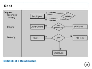
1
C O M P I L E D B Y : G / S L A S S I E E .
2
C O M P I L E D B Y : G / S L A S S I E E .
3
CHAPTER TWO: Conceptual Database design: THE ER Model
 Roles in Database Environment
 Data Representation Model
 Entities (Strong, Weak and Associative)
 Attributes
 Simple (Atomic) vs. Composite Attributes
 Single-Valued vs. Multi-Valued Attributes
 Stored vs. Derived Attribute
 Null Values Attribute
 Concept of Key Attributes
• (Super key, Candidate key and Primary key)
 Relationship
 DEGREE of a Relationship
• (Unary/Recursive, Binary, Ternary, N-nary)
 Role Names and Recursive Relationships
 CARDINALITY of a Relationship (1:1, 1:N, N:1, N:N)
 Entity Relationship Diagrams (ERDs)
C O M P I L E D B Y : G / S L A S S I E E .
Cont.
Roles in Database Environment
 Roles in database environment will be at different
levels of database design and development.
 Here more emphasis is given to the design phases of
the system development life cycle.
 Accordingly the major steps in database design are;
 Planning: that is identifying information gap in an
organization and propose a database solution to solve the
problem.
 Analysis: that concentrates more on fact finding about
the problem or the opportunity. Possibility analysis,
requirement determination and structuring, and selection
of best design method are also performed at this phase.
 Design: in database designing more emphasis is given to
this phase. The phase is further divided into three sub-
phases: Conceptual, Logical and Physical.
4
C O M P I L E D B Y : G / S L A S S I E E .
Cont.
Conceptual Design
 Concise description of the data, data type, relationship
between data and constraints on the data. There is no
implementation or physical detail consideration.
 Conceptual design is the process of constructing a
model of the information used in an enterprise.
 It is the source of information for the logical design
phase.
 Mostly uses an Entity Relationship Model to describe
the data at this level.
 After the completion of Conceptual Design one has to
go for refinement of the schema, which is verification
of Entities, Attributes, and Relationships.
5
C O M P I L E D B Y : G / S L A S S I E E .
Cont.
Logical Design
 A higher level conceptual abstraction with selected
specific data model to implement the data structure.
 Logical design is the process of constructing a model
of the information used in an enterprise based on a
specific data model (e.g. relational, hierarchical or
network or object oriented), but independent of a
particular DBMS and other physical considerations.
Physical Design
 It is the process of producing a description of the
implementation of the database on secondary storage.
 Defines specific storage or access methods used by
database. customized to a specific DBMS system
operating systems.
 Develop all technology & organizational specification.
6
C O M P I L E D B Y : G / S L A S S I E E .
Cont.
 Implementation: the testing and deployment of the
designed database for use.
 Operation and Support: administering and maintaining
the operation of the database system and providing
support to users.
 As people are one of the components in DBMS
environment, there are group of roles played by
different stakeholders at the different levels of the
designing and operation of a database system
 DB Designer
 Application Programmer and System Analyst
 DB Administrator
 User
7
C O M P I L E D B Y : G / S L A S S I E E .
Cont.
Database Designer (DBD)
 Identifies the data to be stored and choose the appropriate
structures to represent and store the data.
 Should understand the user requirement and should choose
how the user views the database.
 We have two distinctions of database designers, one
involving in the logical and conceptual design and another
involving in physical design.
System Analyst and Application Programmer
 The Systems Analyst looks at the requirements, considers
and other aspects of the requirements, and designs the
solution at the systems level and design the external
interfaces and functionality of each piece.
 The Programmer / Software Engineer takes the design from
the analyst and implements / codes each component, testing
along the way to ensure that the implementation meets the
design.
8
C O M P I L E D B Y : G / S L A S S I E E .
Cont.
Database Administrator (DBA)
 Responsible to oversee, control and manage the
database resources (the database itself, the DBMS and
other related software)
 Coordinating and monitoring the use of the database.
 Accountable for problems like poor security, poor
performance of the system.
 Responsible for determining and acquiring hardware
and software resources.
 Involves in all steps of database development
 Further classifications of this role in big organizations
having huge (vast) amount of data and user
requirement.
 Data Administrator (DA)
 Database Administrator (DBA)
9
C O M P I L E D B Y : G / S L A S S I E E .
Cont.
Data Administrator (DA)
 It is responsible on management of data resources.
 Involves in database planning, development,
maintenance of standards policies and procedures at
the conceptual and logical design phases.
 The DA position being largely managerial job has the
following primary roles:-
 To provide centralized control over the data for the
entire organization.
 To set data definition standards to ensure the all
the applications use consistent format and naming
conventions.
10
C O M P I L E D B Y : G / S L A S S I E E .
Cont.
Database Administrator (DBA)
 It is more technically oriented role.
 Responsible for the physical realization of the
database.
 Involves in physical design, implementation, security
and integrity control of the database.
 The basic tasks are performance monitoring, backup
and recovery, and assigning and controlling security.
 Database administrators are trained in the details of
installing, configuring and operating the DBMS.
11
C O M P I L E D B Y : G / S L A S S I E E .
Cont.
 Information System development with Database application
consists of several tasks which include:
 Planning of Information systems Design
 Requirements Analysis,
 Database Design (Conceptual, Logical & Physical Design)
 Interface, program etc designs are also there
 Implementation
 Operation and Support
 In developing a good design, one should answer such
questions as:
 What are the relevant Entities for the Organization
 What are the important features of each Entity
 What are the important Relationships
 What are the important queries from the user
 What are the other requirements of the Organization and
the Users 12
C O M P I L E D B Y : G / S L A S S I E E .
Cont.
Data Representation Model
 Reality is what exists in the real world. This reality
might be in a physical or logical form.
 The representation would be by considering the
properties the reality exhibits.
 When these properties assume a specific value it
would represent the real world object for which data is
required to be captured for.
 Thus any data model will be having a representation
mechanism for building blocks of data representation.
 Building blocks of a data representation model are:
1. Entities
2. Attributes
3. Relationship
13
C O M P I L E D B Y : G / S L A S S I E E .
Cont.
1. The ENTITIES
 Real world physical or logical object for which data
need to be captured for
 Physical existence (tangible) a particular person,
car, house or employee.
 Logical existence (in tangible) a company, a job or
a university course.
 The name given to an entity should always be a
singular noun descriptive of each item to be stored in
it. E.g.: student NOT students
 Every relation has a schema, which describes the
columns, or fields the relation itself corresponds to our
familiar notion of a table
 A relation is a collection of tuples, each of which
contains values for a fixed number of attributes.
14
C O M P I L E D B Y : G / S L A S S I E E .
Cont.
Classification of Entities
 Entity sets can be broadly classified into 3:
1. Strong Entity - is one whose existence does not
depend on other entity and having a primary key
(key attribute). A strong entity is represented by
single-lined rectangle. E.g.: Student (Strong entity) 
Stud_ID (attribute)
2. Weak Entity - is one whose existence depends on
other entity and do not have a primary key. A weak
entity is represented by double-lined rectangle.
E.g.: Grade (Weak entity)  Depend on Student (Strong entity)
3. Associative Entity - is an entity that is formed
when two different entities are related using a
many to many relationship.
Student (Strong entity)  Stud_ID Course (Strong entity)  C_Code
Course Taken (Associative entity)
15
C O M P I L E D B Y : G / S L A S S I E E .
Cont.
2. The ATTRIBUTES
 Properties used to describe each Entity or real world
object.
 Attributes are pieces of information about entities.
 The items of information which characterize and
describe these entities.
 Attributes will give rise to recorded items of data in
the database.
 At this level we need to know such things as:
 Attribute name (be explanatory words or phrases)
 The Domain from which attribute values are taken
(A Domain is a set of values from which attribute
values may be taken.)
16
C O M P I L E D B Y : G / S L A S S I E E .
Cont.
 Whether it is Permanent or Time-Varying (which
attributes may change their values over time) E.g: Age
 Whether it is Required or Optional for the entity
(whose values will sometimes be unknown or
irrelevant) E.g: House Number
Types of Attributes
1. Simple (Atomic) vs. Composite Attributes
 Simple : contains a single value (not divided into
sub parts)
E.g. Age, Gender
 Composite: Divided into sub parts (composed of
other attributes)
E.g. Name, Address
17
C O M P I L E D B Y : G / S L A S S I E E .
Cont.
2. Single-Valued vs. Multi-Valued Attributes
 Single-valued : have only single value (the value
may change but has only one value at one time)
E.g. Name, Sex, Id. No., Color_Of_Eyes
 Multi-Valued: have more than one value
E.g. Dependent-Name, College Degrees attribute for
a person; Person may have several college degrees
3. Stored vs. Derived Attribute
 Stored : not possible to derive or compute
E.g. Name, Address
 Derived: The value may be derived (computed)
from the values of other attributes.
E.g. Age (current year – year of birth); Length of
employment (current date- start date); Profit
(earning-cost); G.P.A (grade point/credit hours)
18
C O M P I L E D B Y : G / S L A S S I E E .
Cont.
4. Null Values (Null “Ok” Attributes)
 NULL applies to attributes which are not applicable or
which do not have values. The meaning of the Null is
Unknown.
 You may enter the value NA (meaning not applicable)
 The category of Null can be further classified into two
cases.
 When it is known that the attribute value exists but
is missing. E.g, if the Height attribute of a person is
listed as null.
 When it is not known whether the attribute value
exists. E.g, if the Home Phone attribute of a person
is null.
19
C O M P I L E D B Y : G / S L A S S I E E .
Cont.
5. Key Attribute
 An important constraint on the entities of an entity
type is the key or uniqueness constraint on attributes.
 Key Attribute - its values can be used to identify each
entity uniquely.
 E.g, the Name attribute is a key of the Company entity
type, because no two companies are allowed to have
the same name.
 For the Person entity type, a typical key attribute is
Social Security Number (SSN).
20
C O M P I L E D B Y : G / S L A S S I E E .
Cont.
Concept of Key Attributes
 Key is an attribute or group of attributes, which is
used to identify a row in a relation.
 Key can be broadly classified into three:-
1. Super key
2. Candidate key, and
3. Primary key
 E.g: - Consider the ‘Employee’ relation, which is
characterized by the attributes (EID, EName, Age,
Experience, and Salary).
1. Super key: - is a subset of attributes of an entity-set
that uniquely identifies the entities. Super keys
represent a constraint that prevents two entities from
ever having the same value for those attributes.
 Super keys can be EID, EName, Age, and Experience.
21
C O M P I L E D B Y : G / S L A S S I E E .
Cont.
2. Candidate Key: is a smallest super key. A candidate
key for a relation schema is a smallest set of attributes
whose values uniquely identify tuples in the
corresponding relation.
 In such case, one of candidate key is chosen to be
primary key, the remaining candidate key are called
Alternate Keys.
 Candidate keys can be EID, EName, Age.
3. Primary Key: is a designated candidate key.
 It is to be noted that the primary key should not be
null and redundant (it has to be distinct).
 Primary key is EID.
 Foreign Key - is set of fields or attributes in one
relation that is used to “refer” to a tuple in another
relation.
22
C O M P I L E D B Y : G / S L A S S I E E .
Cont.
3. The RELATIONSHIPS
 Associations between entities which exist and must be
taken into account when processing information.
 Association is what we call a RELATIONSHIP between
entity objects.
 A relationship should be named by a word or phrase
which explains its function.
 For each RELATIONSHIP,
 One can talk about DEGREE (the number of entities)
 The CARDINALITY (number of tuples or row)
participating in the association.
23
C O M P I L E D B Y : G / S L A S S I E E .
Cont.
DEGREE of a Relationship
 An important point about a relationship is how many
entities participate in it.
 The number of entities participating in a relationship is
called the DEGREE of the relationship. Among the
Degrees of relationship, the following are the basic:
 Unary/Recursive Relationship: Tuples/records of a
Single entity are related withy each other.
 Binary Relationships: Tuples/records of two entities
are associated in a relationship.
 Ternary Relationship: Tuples/records of three different
entities are associated.
And a generalized one:
 N-nary Relationship: Tuples from arbitrary number of
entity sets are participating in a relationship.
24
C O M P I L E D B Y : G / S L A S S I E E .
25
Unary/Recursive Relationship
Binary Relationships
C O M P I L E D B Y : G / S L A S S I E E .
Cont.
26
DEGREE of a Relationship
C O M P I L E D B Y : G / S L A S S I E E .
Cont.
Role Names and Recursive Relationships
 The Role Name signifies the role that a participating
entity from the entity type plays in each relationship
instance, and helps to explain what the relationship
means.
 However, in some cases the same entity type
participates more than once in a relationship type in
different roles.
 In such cases the role name becomes essential for
distinguishing the meaning of each participates. Such
relationship types are called Recursive Relationships.
 E.g. The SUPERVISION relationship type relates an employee
to a supervisor, where both employee and supervisor entities
are members of the same EMPLOYEE entity type.
 Hence, the EMPLOYEE entity type participates twice in
SUPERVISION: once in the role of supervisor (or boss), and
once in the role of supervisee (or subordinate). 27
C O M P I L E D B Y : G / S L A S S I E E .
Cont.
28
C O M P I L E D B Y : G / S L A S S I E E .
Cont.
CARDINALITY of a Relationship
The major cardinalities of a relationship are:
 ONE-TO-ONE (1:1): one tuple is associated with only
one other tuple.
E.g. Building – Location: as a single building will be located
in a single location and as a single location will only
accommodate a single Building.
Head – Department: A Department head manages A
Department.
 ONE-TO-MANY (1:N): one tuple can be associated with
many other tuples, but not the reverse.
E.g. Department – Student: as one department can have
multiple students.
29
C O M P I L E D B Y : G / S L A S S I E E .
Cont.
 MANY-TO-ONE (N:1): many tuples are associated with
one tuple but not the reverse.
E.g. Employee – Department: as many employees belong to
a single department.
 MANY-TO-MANY (N:N): one tuple is associated with
many other tuples and from the other side, with a
different role name one tuple will be associated with
many tuples.
E.g. Student – Course: as a student can take many
courses and a single course can be attended by many
students.
30
C O M P I L E D B Y : G / S L A S S I E E .
Cont.
31
CARDINALITY of a Relationship
C O M P I L E D B Y : G / S L A S S I E E .
Cont.
Participation of an Entity Set in a Relationship Set
 Participation constraint of a relationship is involved in
identifying and setting the required or optional feature
of an entity occurrence to take a role in a relationship.
 There are two distinct participation constraints with
this respect, namely:
 Total Participation and
 Partial Participation
32
C O M P I L E D B Y : G / S L A S S I E E .
Cont.
Total Participation:
 Every tuple in the entity or relation participates in at
least one relationship by taking a role.
 This means, every tuple in a relation will be attached
with at least one other tuple.
 The entity with total participation in a relationship will
be connected to the relationship using a double line.
Partial Participation:
 Some tuple in the entity or relation may not participate
in the relationship.
 This means, there is at least one tuple from that
Relation not taking any role in that specific
relationship.
 The entity with partial participation in a relationship
will be connected to the relationship using a single
line. 33
C O M P I L E D B Y : G / S L A S S I E E .
Cont.
 E.g. 1:Participation of EMPLOYEE in “belongs to” relationship with
DEPARTMENT is TOTAL PARTICIPATION since every employee should
belong to a department.
 Participation of DEPARTMENT in “belongs to” relationship with
EMPLOYEE is total since every department should have more than
one employee.
 E.g. 2:Participation of EMPLOYEE in “manages” relationship with
DEPARTMENT, is PARTIAL PARTICIPATION since not all employees
are managers.
 Participation of DEPARTMENT in “Manages” relationship with
EMPLOYEE is total since every department should have a manager.
34
Employee Department
Belongs
To
Employee Department
Manages
C O M P I L E D B Y : G / S L A S S I E E .
35
Cardinality Constraints
C O M P I L E D B Y : G / S L A S S I E E .
A) Mandatory cardinalities
A patient must have
recorded at least one
history, and can have many
A patient history is
recorded for one and
only one patient
36
C O M P I L E D B Y : G / S L A S S I E E .
37
B) One Mandatory, One Optional
An employee can be assigned to
any number of projects, or may
not be assigned to any at all
A project must be assigned to
at least one employee, and
may be assigned to many
C O M P I L E D B Y : G / S L A S S I E E .
C) Optional Cardinalities
A person is married
to at most one
other person, or
may not be married
at all
38
C O M P I L E D B Y : G / S L A S S I E E .
Cont.
Conceptual Database Design
 Conceptual design revolves around discovering and
analyzing organizational and user data requirements
 The important activities are to identify
 Entities
 Attributes
 Relationships
 Constraints
 And based on these components develop the ER model
using ER diagram components.
39
C O M P I L E D B Y : G / S L A S S I E E .
Cont.
 Before working on the conceptual design of the
database, one has to know and answer the following
basic questions
 What are the entities and relationships in the
enterprise?
 What information about these entities and
relationships should we store in the database?
 What are the integrity constraints that hold?
• Constraints on each data with respect to update,
retrieval and store.
 Represent this information pictorially in ER
diagrams, then map ER diagram into a relational
schema.
40
C O M P I L E D B Y : G / S L A S S I E E .
Cont.
Modeling Tools
 There are many ER diagramming tools:
 Rational Rose, Microsoft Visio, Oracle Designer,
Power Designer etc.
 To identify the entities, attributes, relationships, and
constraints on the data, there are different set of
methods used during the analysis phase.
 These include information gathered through
 Interviewing end users individually and in a group
 Questionnaire survey
 Direct observation
 Examining different documents
 Generally understand the business rules
41
C O M P I L E D B Y : G / S L A S S I E E .
Cont.
Entity Relationship Diagrams (ERDs)
 ERDs are a major data modeling tool and will help
organize the data in your project into entities and
define the relationships between the entities.
 This process has proved to enable the analyst to
produce a good database structure so that the data
can be stored and retrieved in a most efficient manner.
 By using a graphical format it may help communication
about the design between the designer and the user
and the designer and the people who will implement it.
 Note: An entity type is represented in ER diagrams (We
are using a notation for ER diagrams that is close to
the original proposed notation (Chen 1976)).
42
C O M P I L E D B Y : G / S L A S S I E E .
Cont.
Steps: Creating an ERD
 Here are the steps you may follow to create an entity-
relationship diagram.
 Identify Entities:
• These are typically the nouns and noun-phrases in
the descriptive data produced in your analysis.
• Do not include entities that are irrelevant to your
domain.
 Find Relationships:
• These are usually the verbs that connect the nouns.
• Not all relationships are this obvious, you may have
to discover some on your own.
• The easiest way to see all possible relationships is
to build a table with the entities across the columns
and down the rows, and fill in those cells where a
relationship exists between entities. 43
C O M P I L E D B Y : G / S L A S S I E E .
Cont.
 Draw Rough ERD:
• Draw the entities and relationships that you have
discovered.
 Fill in Cardinality:
• Determine the cardinality of the relationships.
• You may want to decide on cardinality when you
are creating a relationship table.
 Define Primary Keys:
• Identify attribute(s) that uniquely identify each
occurrence of that entity.
 Draw Key-Based ERD:
• Now add them (the primary key attributes) to your
ERD.
• Revise your diagram to eliminate many-to-many
relationships, and tag all foreign keys .
44
C O M P I L E D B Y : G / S L A S S I E E .
Cont.
 Identify Attributes:
• Identify all entity characteristics relevant to the
domain being analyzed.
 Map Attributes:
• Determine to which entity each characteristic
belongs.
• Do not duplicate attributes across entities.
 Draw fully attributed ERD:
• Now add these attributes.
• The diagram may need to be modified to
accommodate necessary new entities.
 Check Results:
• Is the diagram a consistent and complete
representation of the domain.
45
C O M P I L E D B Y : G / S L A S S I E E .
Cont.
Basic ER-Diagram Notation
The following figures the respective terms in ER-Diagram:
46
For Multivalued Attributes
For Derived Attributes
For Strong Entity
For Weak Entity For Simple and Single
Valued Attributes
For Key Attributes
For Strong Relationship
For Weak Relationship
To Connect the Attribute
and Entity Relationships
For Associative Entity
C O M P I L E D B Y : G / S L A S S I E E .
Cardinality and Participation Constraints
47
C O M P I L E D B Y : G / S L A S S I E E .
48
C O M P I L E D B Y : G / S L A S S I E E .
49
Example of Entity, Attributes and Relationship
C O M P I L E D B Y : G / S L A S S I E E .
Cont.
Refining the ER Design for the COMPANY Database: -
 In our E.g., we specify the following relationship types:
 MANAGES, a 1:1 relationship type between EMPLOYEE and
DEPARTMENT.
 WORKS_FOR, a 1: N relationship type between DEPARTMENT and
EMPLOYEE.
 CONTROLS, a 1: N relationship type between DEPARTMENT and
PROJECT.
 SUPERVISION, a 1: N relationship type between EMPLOYEE (in
the supervisor role) and EMPLOYEE (in the supervisee role).
 WORKS_ON, determined to be an M: N relationship type with
attribute Hours.
 DEPENDENTS_OF, a 1: N relationship type between EMPLOYEE
and DEPENDENT.
 Shows how the schema for this database application can be displayed by
means of the graphical notation known as ER diagrams. We describe the
process of deriving this schema from the stated requirements and explain the
ER diagrammatic notation as we introduce the ER model concepts in the
following section. 50
C O M P I L E D B Y : G / S L A S S I E E .
51
1
N
Supervisor
1: N
EMPLOYEE
FName MName LName
Name
Sex
BDate
EID
Address
Salary
Location
Number
Name
DEPARTMENT
Num. of Employee
Works For
Manages
N
1
1
1
Composite
Multi-Valued
Derived
PROJECT
Controls
Location
Number Name
Works On
N
N
1
N
Has
Dependent
Supervision
Relationship
BDate
Name
Sex
Supervisee
N: 1
Weak Relationship
Weak Entity
C O M P I L E D B Y : G / S L A S S I E E .

03 CHAPTER TWO - CONCEPTUAL DATABASE DESIGN.pptx

  • 1.
    1 C O MP I L E D B Y : G / S L A S S I E E .
  • 2.
    2 C O MP I L E D B Y : G / S L A S S I E E .
  • 3.
    3 CHAPTER TWO: ConceptualDatabase design: THE ER Model  Roles in Database Environment  Data Representation Model  Entities (Strong, Weak and Associative)  Attributes  Simple (Atomic) vs. Composite Attributes  Single-Valued vs. Multi-Valued Attributes  Stored vs. Derived Attribute  Null Values Attribute  Concept of Key Attributes • (Super key, Candidate key and Primary key)  Relationship  DEGREE of a Relationship • (Unary/Recursive, Binary, Ternary, N-nary)  Role Names and Recursive Relationships  CARDINALITY of a Relationship (1:1, 1:N, N:1, N:N)  Entity Relationship Diagrams (ERDs) C O M P I L E D B Y : G / S L A S S I E E .
  • 4.
    Cont. Roles in DatabaseEnvironment  Roles in database environment will be at different levels of database design and development.  Here more emphasis is given to the design phases of the system development life cycle.  Accordingly the major steps in database design are;  Planning: that is identifying information gap in an organization and propose a database solution to solve the problem.  Analysis: that concentrates more on fact finding about the problem or the opportunity. Possibility analysis, requirement determination and structuring, and selection of best design method are also performed at this phase.  Design: in database designing more emphasis is given to this phase. The phase is further divided into three sub- phases: Conceptual, Logical and Physical. 4 C O M P I L E D B Y : G / S L A S S I E E .
  • 5.
    Cont. Conceptual Design  Concisedescription of the data, data type, relationship between data and constraints on the data. There is no implementation or physical detail consideration.  Conceptual design is the process of constructing a model of the information used in an enterprise.  It is the source of information for the logical design phase.  Mostly uses an Entity Relationship Model to describe the data at this level.  After the completion of Conceptual Design one has to go for refinement of the schema, which is verification of Entities, Attributes, and Relationships. 5 C O M P I L E D B Y : G / S L A S S I E E .
  • 6.
    Cont. Logical Design  Ahigher level conceptual abstraction with selected specific data model to implement the data structure.  Logical design is the process of constructing a model of the information used in an enterprise based on a specific data model (e.g. relational, hierarchical or network or object oriented), but independent of a particular DBMS and other physical considerations. Physical Design  It is the process of producing a description of the implementation of the database on secondary storage.  Defines specific storage or access methods used by database. customized to a specific DBMS system operating systems.  Develop all technology & organizational specification. 6 C O M P I L E D B Y : G / S L A S S I E E .
  • 7.
    Cont.  Implementation: thetesting and deployment of the designed database for use.  Operation and Support: administering and maintaining the operation of the database system and providing support to users.  As people are one of the components in DBMS environment, there are group of roles played by different stakeholders at the different levels of the designing and operation of a database system  DB Designer  Application Programmer and System Analyst  DB Administrator  User 7 C O M P I L E D B Y : G / S L A S S I E E .
  • 8.
    Cont. Database Designer (DBD) Identifies the data to be stored and choose the appropriate structures to represent and store the data.  Should understand the user requirement and should choose how the user views the database.  We have two distinctions of database designers, one involving in the logical and conceptual design and another involving in physical design. System Analyst and Application Programmer  The Systems Analyst looks at the requirements, considers and other aspects of the requirements, and designs the solution at the systems level and design the external interfaces and functionality of each piece.  The Programmer / Software Engineer takes the design from the analyst and implements / codes each component, testing along the way to ensure that the implementation meets the design. 8 C O M P I L E D B Y : G / S L A S S I E E .
  • 9.
    Cont. Database Administrator (DBA) Responsible to oversee, control and manage the database resources (the database itself, the DBMS and other related software)  Coordinating and monitoring the use of the database.  Accountable for problems like poor security, poor performance of the system.  Responsible for determining and acquiring hardware and software resources.  Involves in all steps of database development  Further classifications of this role in big organizations having huge (vast) amount of data and user requirement.  Data Administrator (DA)  Database Administrator (DBA) 9 C O M P I L E D B Y : G / S L A S S I E E .
  • 10.
    Cont. Data Administrator (DA) It is responsible on management of data resources.  Involves in database planning, development, maintenance of standards policies and procedures at the conceptual and logical design phases.  The DA position being largely managerial job has the following primary roles:-  To provide centralized control over the data for the entire organization.  To set data definition standards to ensure the all the applications use consistent format and naming conventions. 10 C O M P I L E D B Y : G / S L A S S I E E .
  • 11.
    Cont. Database Administrator (DBA) It is more technically oriented role.  Responsible for the physical realization of the database.  Involves in physical design, implementation, security and integrity control of the database.  The basic tasks are performance monitoring, backup and recovery, and assigning and controlling security.  Database administrators are trained in the details of installing, configuring and operating the DBMS. 11 C O M P I L E D B Y : G / S L A S S I E E .
  • 12.
    Cont.  Information Systemdevelopment with Database application consists of several tasks which include:  Planning of Information systems Design  Requirements Analysis,  Database Design (Conceptual, Logical & Physical Design)  Interface, program etc designs are also there  Implementation  Operation and Support  In developing a good design, one should answer such questions as:  What are the relevant Entities for the Organization  What are the important features of each Entity  What are the important Relationships  What are the important queries from the user  What are the other requirements of the Organization and the Users 12 C O M P I L E D B Y : G / S L A S S I E E .
  • 13.
    Cont. Data Representation Model Reality is what exists in the real world. This reality might be in a physical or logical form.  The representation would be by considering the properties the reality exhibits.  When these properties assume a specific value it would represent the real world object for which data is required to be captured for.  Thus any data model will be having a representation mechanism for building blocks of data representation.  Building blocks of a data representation model are: 1. Entities 2. Attributes 3. Relationship 13 C O M P I L E D B Y : G / S L A S S I E E .
  • 14.
    Cont. 1. The ENTITIES Real world physical or logical object for which data need to be captured for  Physical existence (tangible) a particular person, car, house or employee.  Logical existence (in tangible) a company, a job or a university course.  The name given to an entity should always be a singular noun descriptive of each item to be stored in it. E.g.: student NOT students  Every relation has a schema, which describes the columns, or fields the relation itself corresponds to our familiar notion of a table  A relation is a collection of tuples, each of which contains values for a fixed number of attributes. 14 C O M P I L E D B Y : G / S L A S S I E E .
  • 15.
    Cont. Classification of Entities Entity sets can be broadly classified into 3: 1. Strong Entity - is one whose existence does not depend on other entity and having a primary key (key attribute). A strong entity is represented by single-lined rectangle. E.g.: Student (Strong entity)  Stud_ID (attribute) 2. Weak Entity - is one whose existence depends on other entity and do not have a primary key. A weak entity is represented by double-lined rectangle. E.g.: Grade (Weak entity)  Depend on Student (Strong entity) 3. Associative Entity - is an entity that is formed when two different entities are related using a many to many relationship. Student (Strong entity)  Stud_ID Course (Strong entity)  C_Code Course Taken (Associative entity) 15 C O M P I L E D B Y : G / S L A S S I E E .
  • 16.
    Cont. 2. The ATTRIBUTES Properties used to describe each Entity or real world object.  Attributes are pieces of information about entities.  The items of information which characterize and describe these entities.  Attributes will give rise to recorded items of data in the database.  At this level we need to know such things as:  Attribute name (be explanatory words or phrases)  The Domain from which attribute values are taken (A Domain is a set of values from which attribute values may be taken.) 16 C O M P I L E D B Y : G / S L A S S I E E .
  • 17.
    Cont.  Whether itis Permanent or Time-Varying (which attributes may change their values over time) E.g: Age  Whether it is Required or Optional for the entity (whose values will sometimes be unknown or irrelevant) E.g: House Number Types of Attributes 1. Simple (Atomic) vs. Composite Attributes  Simple : contains a single value (not divided into sub parts) E.g. Age, Gender  Composite: Divided into sub parts (composed of other attributes) E.g. Name, Address 17 C O M P I L E D B Y : G / S L A S S I E E .
  • 18.
    Cont. 2. Single-Valued vs.Multi-Valued Attributes  Single-valued : have only single value (the value may change but has only one value at one time) E.g. Name, Sex, Id. No., Color_Of_Eyes  Multi-Valued: have more than one value E.g. Dependent-Name, College Degrees attribute for a person; Person may have several college degrees 3. Stored vs. Derived Attribute  Stored : not possible to derive or compute E.g. Name, Address  Derived: The value may be derived (computed) from the values of other attributes. E.g. Age (current year – year of birth); Length of employment (current date- start date); Profit (earning-cost); G.P.A (grade point/credit hours) 18 C O M P I L E D B Y : G / S L A S S I E E .
  • 19.
    Cont. 4. Null Values(Null “Ok” Attributes)  NULL applies to attributes which are not applicable or which do not have values. The meaning of the Null is Unknown.  You may enter the value NA (meaning not applicable)  The category of Null can be further classified into two cases.  When it is known that the attribute value exists but is missing. E.g, if the Height attribute of a person is listed as null.  When it is not known whether the attribute value exists. E.g, if the Home Phone attribute of a person is null. 19 C O M P I L E D B Y : G / S L A S S I E E .
  • 20.
    Cont. 5. Key Attribute An important constraint on the entities of an entity type is the key or uniqueness constraint on attributes.  Key Attribute - its values can be used to identify each entity uniquely.  E.g, the Name attribute is a key of the Company entity type, because no two companies are allowed to have the same name.  For the Person entity type, a typical key attribute is Social Security Number (SSN). 20 C O M P I L E D B Y : G / S L A S S I E E .
  • 21.
    Cont. Concept of KeyAttributes  Key is an attribute or group of attributes, which is used to identify a row in a relation.  Key can be broadly classified into three:- 1. Super key 2. Candidate key, and 3. Primary key  E.g: - Consider the ‘Employee’ relation, which is characterized by the attributes (EID, EName, Age, Experience, and Salary). 1. Super key: - is a subset of attributes of an entity-set that uniquely identifies the entities. Super keys represent a constraint that prevents two entities from ever having the same value for those attributes.  Super keys can be EID, EName, Age, and Experience. 21 C O M P I L E D B Y : G / S L A S S I E E .
  • 22.
    Cont. 2. Candidate Key:is a smallest super key. A candidate key for a relation schema is a smallest set of attributes whose values uniquely identify tuples in the corresponding relation.  In such case, one of candidate key is chosen to be primary key, the remaining candidate key are called Alternate Keys.  Candidate keys can be EID, EName, Age. 3. Primary Key: is a designated candidate key.  It is to be noted that the primary key should not be null and redundant (it has to be distinct).  Primary key is EID.  Foreign Key - is set of fields or attributes in one relation that is used to “refer” to a tuple in another relation. 22 C O M P I L E D B Y : G / S L A S S I E E .
  • 23.
    Cont. 3. The RELATIONSHIPS Associations between entities which exist and must be taken into account when processing information.  Association is what we call a RELATIONSHIP between entity objects.  A relationship should be named by a word or phrase which explains its function.  For each RELATIONSHIP,  One can talk about DEGREE (the number of entities)  The CARDINALITY (number of tuples or row) participating in the association. 23 C O M P I L E D B Y : G / S L A S S I E E .
  • 24.
    Cont. DEGREE of aRelationship  An important point about a relationship is how many entities participate in it.  The number of entities participating in a relationship is called the DEGREE of the relationship. Among the Degrees of relationship, the following are the basic:  Unary/Recursive Relationship: Tuples/records of a Single entity are related withy each other.  Binary Relationships: Tuples/records of two entities are associated in a relationship.  Ternary Relationship: Tuples/records of three different entities are associated. And a generalized one:  N-nary Relationship: Tuples from arbitrary number of entity sets are participating in a relationship. 24 C O M P I L E D B Y : G / S L A S S I E E .
  • 25.
    25 Unary/Recursive Relationship Binary Relationships CO M P I L E D B Y : G / S L A S S I E E .
  • 26.
    Cont. 26 DEGREE of aRelationship C O M P I L E D B Y : G / S L A S S I E E .
  • 27.
    Cont. Role Names andRecursive Relationships  The Role Name signifies the role that a participating entity from the entity type plays in each relationship instance, and helps to explain what the relationship means.  However, in some cases the same entity type participates more than once in a relationship type in different roles.  In such cases the role name becomes essential for distinguishing the meaning of each participates. Such relationship types are called Recursive Relationships.  E.g. The SUPERVISION relationship type relates an employee to a supervisor, where both employee and supervisor entities are members of the same EMPLOYEE entity type.  Hence, the EMPLOYEE entity type participates twice in SUPERVISION: once in the role of supervisor (or boss), and once in the role of supervisee (or subordinate). 27 C O M P I L E D B Y : G / S L A S S I E E .
  • 28.
    Cont. 28 C O MP I L E D B Y : G / S L A S S I E E .
  • 29.
    Cont. CARDINALITY of aRelationship The major cardinalities of a relationship are:  ONE-TO-ONE (1:1): one tuple is associated with only one other tuple. E.g. Building – Location: as a single building will be located in a single location and as a single location will only accommodate a single Building. Head – Department: A Department head manages A Department.  ONE-TO-MANY (1:N): one tuple can be associated with many other tuples, but not the reverse. E.g. Department – Student: as one department can have multiple students. 29 C O M P I L E D B Y : G / S L A S S I E E .
  • 30.
    Cont.  MANY-TO-ONE (N:1):many tuples are associated with one tuple but not the reverse. E.g. Employee – Department: as many employees belong to a single department.  MANY-TO-MANY (N:N): one tuple is associated with many other tuples and from the other side, with a different role name one tuple will be associated with many tuples. E.g. Student – Course: as a student can take many courses and a single course can be attended by many students. 30 C O M P I L E D B Y : G / S L A S S I E E .
  • 31.
    Cont. 31 CARDINALITY of aRelationship C O M P I L E D B Y : G / S L A S S I E E .
  • 32.
    Cont. Participation of anEntity Set in a Relationship Set  Participation constraint of a relationship is involved in identifying and setting the required or optional feature of an entity occurrence to take a role in a relationship.  There are two distinct participation constraints with this respect, namely:  Total Participation and  Partial Participation 32 C O M P I L E D B Y : G / S L A S S I E E .
  • 33.
    Cont. Total Participation:  Everytuple in the entity or relation participates in at least one relationship by taking a role.  This means, every tuple in a relation will be attached with at least one other tuple.  The entity with total participation in a relationship will be connected to the relationship using a double line. Partial Participation:  Some tuple in the entity or relation may not participate in the relationship.  This means, there is at least one tuple from that Relation not taking any role in that specific relationship.  The entity with partial participation in a relationship will be connected to the relationship using a single line. 33 C O M P I L E D B Y : G / S L A S S I E E .
  • 34.
    Cont.  E.g. 1:Participationof EMPLOYEE in “belongs to” relationship with DEPARTMENT is TOTAL PARTICIPATION since every employee should belong to a department.  Participation of DEPARTMENT in “belongs to” relationship with EMPLOYEE is total since every department should have more than one employee.  E.g. 2:Participation of EMPLOYEE in “manages” relationship with DEPARTMENT, is PARTIAL PARTICIPATION since not all employees are managers.  Participation of DEPARTMENT in “Manages” relationship with EMPLOYEE is total since every department should have a manager. 34 Employee Department Belongs To Employee Department Manages C O M P I L E D B Y : G / S L A S S I E E .
  • 35.
    35 Cardinality Constraints C OM P I L E D B Y : G / S L A S S I E E .
  • 36.
    A) Mandatory cardinalities Apatient must have recorded at least one history, and can have many A patient history is recorded for one and only one patient 36 C O M P I L E D B Y : G / S L A S S I E E .
  • 37.
    37 B) One Mandatory,One Optional An employee can be assigned to any number of projects, or may not be assigned to any at all A project must be assigned to at least one employee, and may be assigned to many C O M P I L E D B Y : G / S L A S S I E E .
  • 38.
    C) Optional Cardinalities Aperson is married to at most one other person, or may not be married at all 38 C O M P I L E D B Y : G / S L A S S I E E .
  • 39.
    Cont. Conceptual Database Design Conceptual design revolves around discovering and analyzing organizational and user data requirements  The important activities are to identify  Entities  Attributes  Relationships  Constraints  And based on these components develop the ER model using ER diagram components. 39 C O M P I L E D B Y : G / S L A S S I E E .
  • 40.
    Cont.  Before workingon the conceptual design of the database, one has to know and answer the following basic questions  What are the entities and relationships in the enterprise?  What information about these entities and relationships should we store in the database?  What are the integrity constraints that hold? • Constraints on each data with respect to update, retrieval and store.  Represent this information pictorially in ER diagrams, then map ER diagram into a relational schema. 40 C O M P I L E D B Y : G / S L A S S I E E .
  • 41.
    Cont. Modeling Tools  Thereare many ER diagramming tools:  Rational Rose, Microsoft Visio, Oracle Designer, Power Designer etc.  To identify the entities, attributes, relationships, and constraints on the data, there are different set of methods used during the analysis phase.  These include information gathered through  Interviewing end users individually and in a group  Questionnaire survey  Direct observation  Examining different documents  Generally understand the business rules 41 C O M P I L E D B Y : G / S L A S S I E E .
  • 42.
    Cont. Entity Relationship Diagrams(ERDs)  ERDs are a major data modeling tool and will help organize the data in your project into entities and define the relationships between the entities.  This process has proved to enable the analyst to produce a good database structure so that the data can be stored and retrieved in a most efficient manner.  By using a graphical format it may help communication about the design between the designer and the user and the designer and the people who will implement it.  Note: An entity type is represented in ER diagrams (We are using a notation for ER diagrams that is close to the original proposed notation (Chen 1976)). 42 C O M P I L E D B Y : G / S L A S S I E E .
  • 43.
    Cont. Steps: Creating anERD  Here are the steps you may follow to create an entity- relationship diagram.  Identify Entities: • These are typically the nouns and noun-phrases in the descriptive data produced in your analysis. • Do not include entities that are irrelevant to your domain.  Find Relationships: • These are usually the verbs that connect the nouns. • Not all relationships are this obvious, you may have to discover some on your own. • The easiest way to see all possible relationships is to build a table with the entities across the columns and down the rows, and fill in those cells where a relationship exists between entities. 43 C O M P I L E D B Y : G / S L A S S I E E .
  • 44.
    Cont.  Draw RoughERD: • Draw the entities and relationships that you have discovered.  Fill in Cardinality: • Determine the cardinality of the relationships. • You may want to decide on cardinality when you are creating a relationship table.  Define Primary Keys: • Identify attribute(s) that uniquely identify each occurrence of that entity.  Draw Key-Based ERD: • Now add them (the primary key attributes) to your ERD. • Revise your diagram to eliminate many-to-many relationships, and tag all foreign keys . 44 C O M P I L E D B Y : G / S L A S S I E E .
  • 45.
    Cont.  Identify Attributes: •Identify all entity characteristics relevant to the domain being analyzed.  Map Attributes: • Determine to which entity each characteristic belongs. • Do not duplicate attributes across entities.  Draw fully attributed ERD: • Now add these attributes. • The diagram may need to be modified to accommodate necessary new entities.  Check Results: • Is the diagram a consistent and complete representation of the domain. 45 C O M P I L E D B Y : G / S L A S S I E E .
  • 46.
    Cont. Basic ER-Diagram Notation Thefollowing figures the respective terms in ER-Diagram: 46 For Multivalued Attributes For Derived Attributes For Strong Entity For Weak Entity For Simple and Single Valued Attributes For Key Attributes For Strong Relationship For Weak Relationship To Connect the Attribute and Entity Relationships For Associative Entity C O M P I L E D B Y : G / S L A S S I E E .
  • 47.
    Cardinality and ParticipationConstraints 47 C O M P I L E D B Y : G / S L A S S I E E .
  • 48.
    48 C O MP I L E D B Y : G / S L A S S I E E .
  • 49.
    49 Example of Entity,Attributes and Relationship C O M P I L E D B Y : G / S L A S S I E E .
  • 50.
    Cont. Refining the ERDesign for the COMPANY Database: -  In our E.g., we specify the following relationship types:  MANAGES, a 1:1 relationship type between EMPLOYEE and DEPARTMENT.  WORKS_FOR, a 1: N relationship type between DEPARTMENT and EMPLOYEE.  CONTROLS, a 1: N relationship type between DEPARTMENT and PROJECT.  SUPERVISION, a 1: N relationship type between EMPLOYEE (in the supervisor role) and EMPLOYEE (in the supervisee role).  WORKS_ON, determined to be an M: N relationship type with attribute Hours.  DEPENDENTS_OF, a 1: N relationship type between EMPLOYEE and DEPENDENT.  Shows how the schema for this database application can be displayed by means of the graphical notation known as ER diagrams. We describe the process of deriving this schema from the stated requirements and explain the ER diagrammatic notation as we introduce the ER model concepts in the following section. 50 C O M P I L E D B Y : G / S L A S S I E E .
  • 51.
    51 1 N Supervisor 1: N EMPLOYEE FName MNameLName Name Sex BDate EID Address Salary Location Number Name DEPARTMENT Num. of Employee Works For Manages N 1 1 1 Composite Multi-Valued Derived PROJECT Controls Location Number Name Works On N N 1 N Has Dependent Supervision Relationship BDate Name Sex Supervisee N: 1 Weak Relationship Weak Entity C O M P I L E D B Y : G / S L A S S I E E .