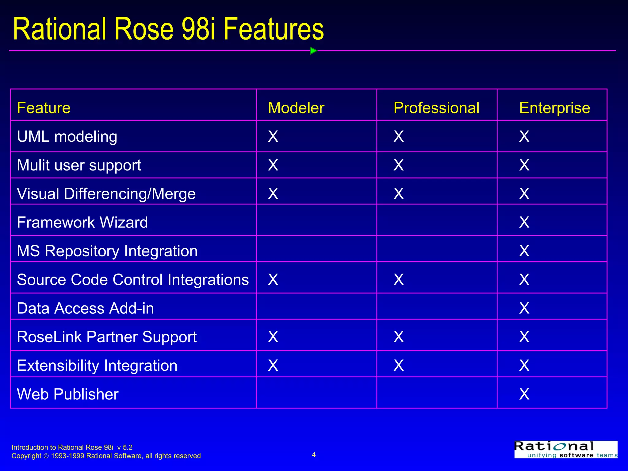
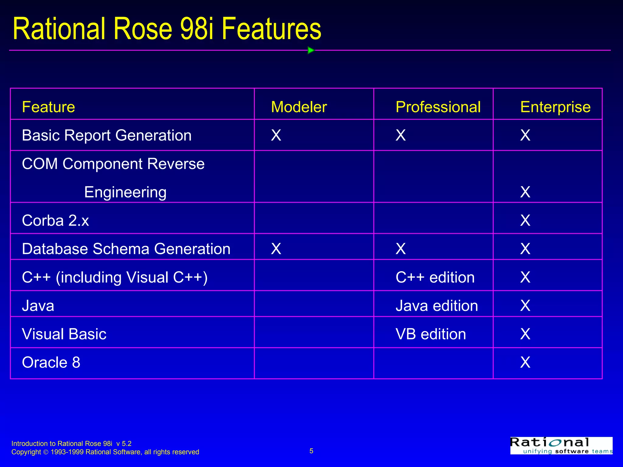
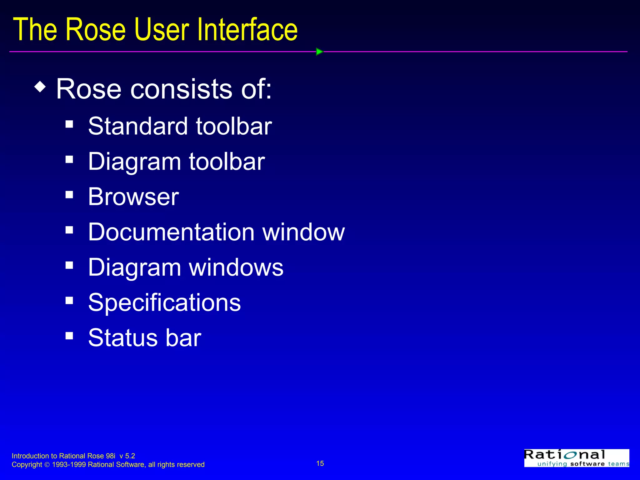
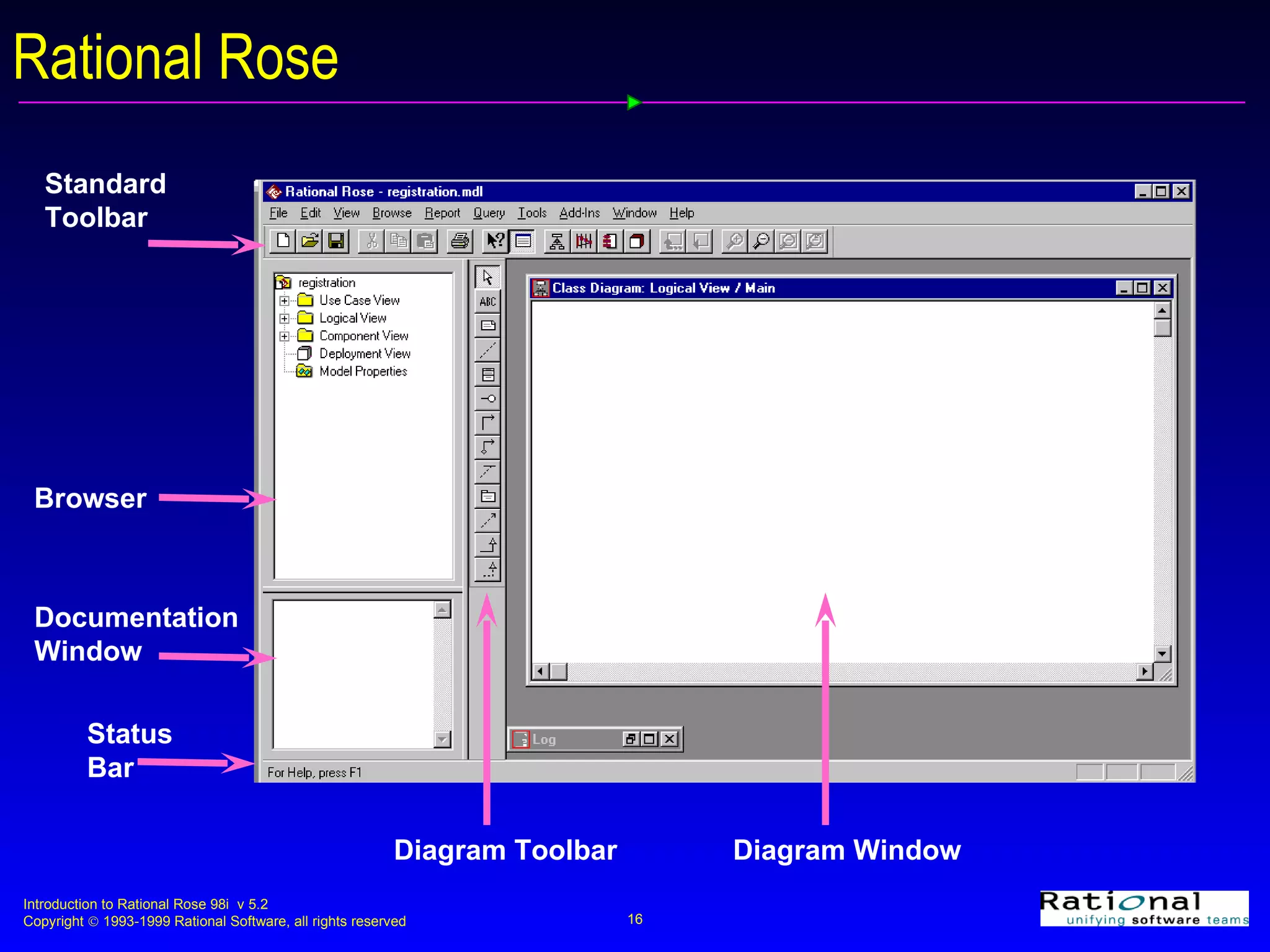
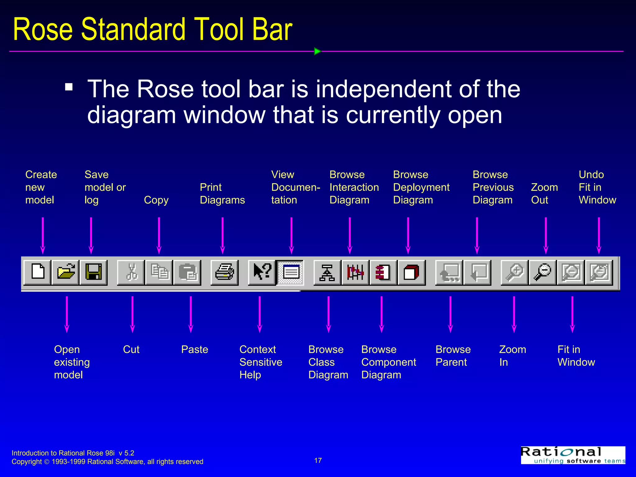
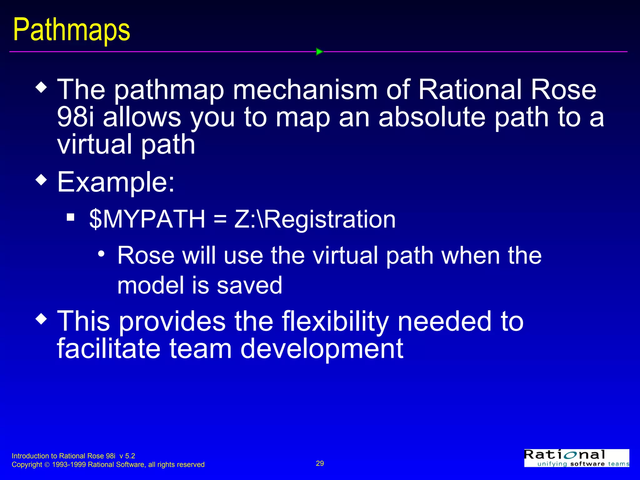
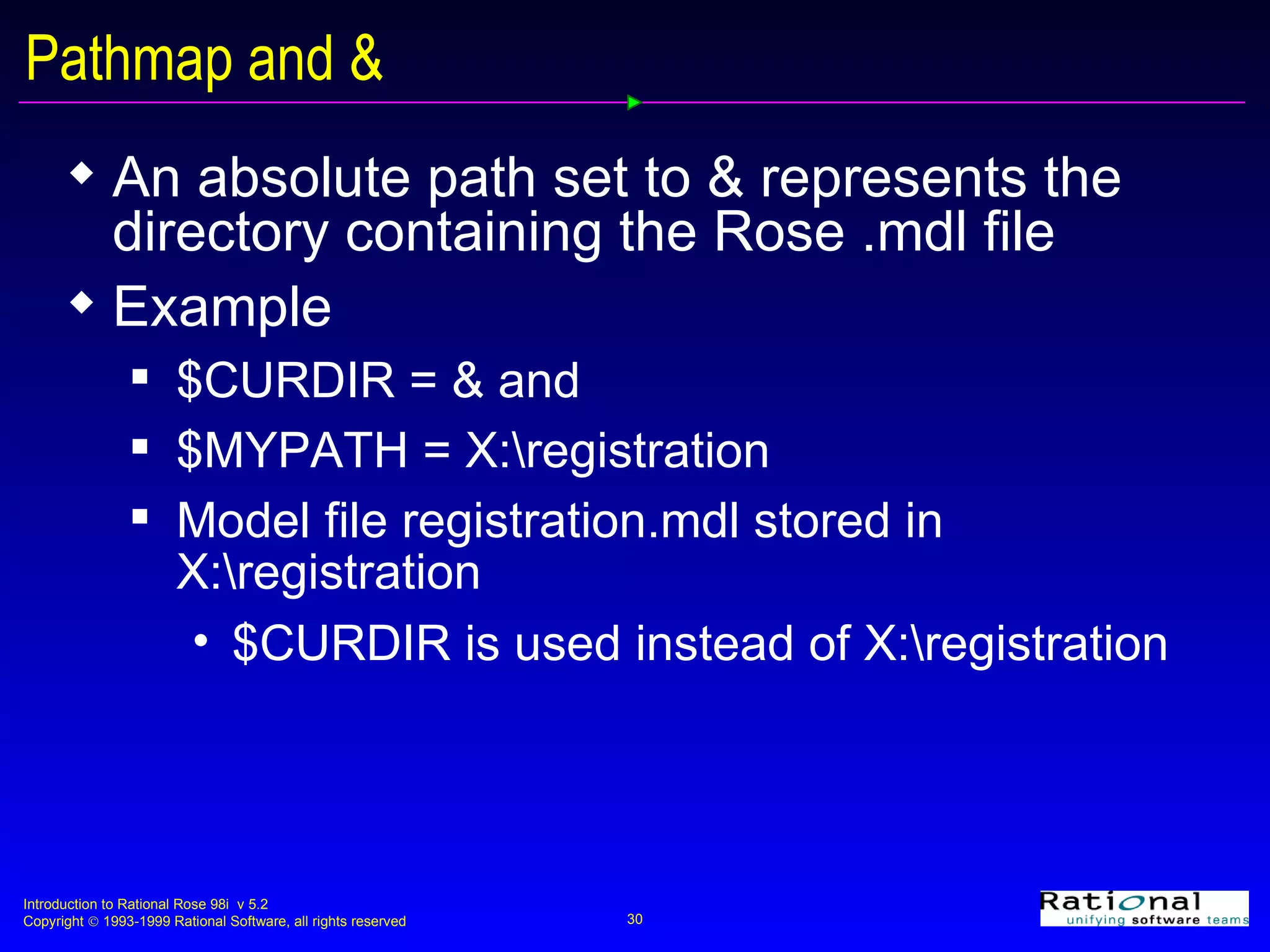
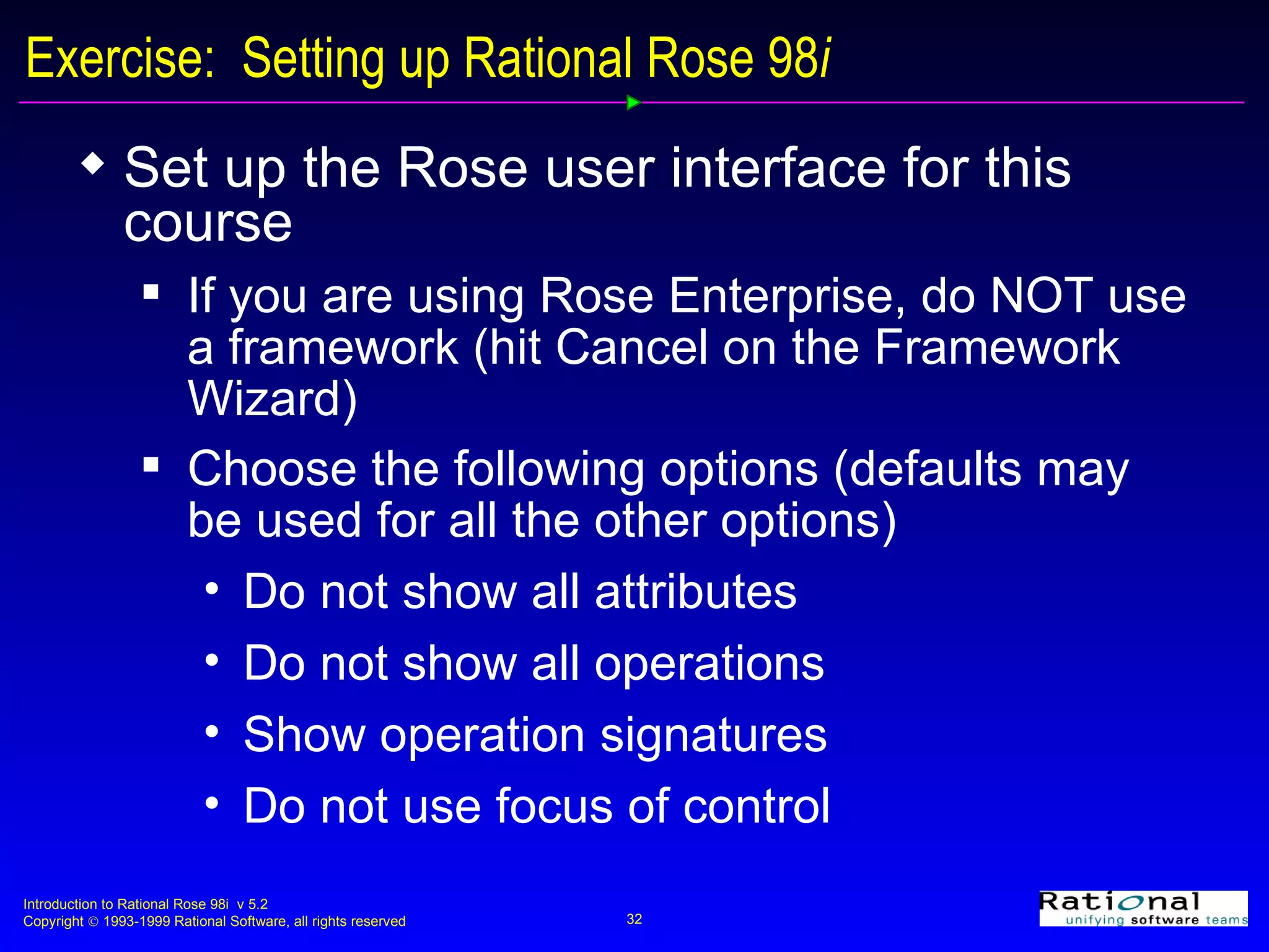
Introduction to Rational Rose 98i Module 2: Introduction
Objectives:  Introduction On completion of this module participants will be able to: Discuss the different views supported by Rational Rose 98i List the diagrams for each view Discuss elements common to each view Configure the Rational Rose 98i interface
What is Rational Rose 98i? Rational Rose 98i is a tool with the capability to create, view, modify, and manipulate components in a Rose model Rational Rose 98i supports the Unified, Booch, and OMT notations Rational Rose 98i is available in three editions: Rational Rose 98i Modeler  Rational Rose 98i Professional for C++, Java, or Visual Basic Rational Rose 98i Enterprise
Rational Rose 98i Features Feature Modeler Professional Enterprise UML modeling X X X Mulit user support X X X Visual Differencing/Merge X X X Framework Wizard X MS Repository Integration X Source Code Control Integrations X X X Data Access Add-in X RoseLink Partner Support X X X Extensibility Integration X X X Web Publisher X
Rational Rose 98i Features Feature Modeler Professional Enterprise Basic Report Generation X X X COM Component Reverse  Engineering     X Corba 2.x      X Database Schema Generation X X X C++ (including Visual C++) C++ edition X Java Java edition X Visual Basic VB edition X Oracle 8 X
What is a Rose Model? A Rose “model” is a representation of the problem domain and system software Each model contains views, diagrams, and specifications to visualize and manipulate the elements in the model There are many views of each underlying element Every “object” in the design is represented once in the Rose “model” Rose maintains a consistent semantic representation in the “model”
Use Case View Diagrams Elements in the use case view may be viewed in one or more diagrams The use case view contains any or all of the following diagrams Use case diagrams Packages, actors, use cases, and relationships Interaction diagrams (sequence diagrams and/or collaboration diagrams) Objects and messages Activity diagrams Activities, transitions , forks, joins, decisions, and swimlanes
Use Case Diagram A use case diagram shows what should be performed by the system and what exists outside the system It shows the existence of actors (outside the system), use cases (what should be performed by the system), and their relationships  A use-case diagram may depict all or some of the use cases of a system
Interaction Diagrams Interaction diagrams show the existence of objects and their relationships in the logical design of a system They may represent all or part of the object structure of a system There are two kinds of interaction diagrams, each shows a different view of the same interaction A sequence diagram shows object interactions arranged in time sequence A collaboration diagram is organized around the objects and their links to each other
Logical View Diagrams Elements in the logical view may be viewed in one or more diagrams The logical view contains any or all of the following diagrams Class diagrams Packages, classes, and relationships State diagrams States, events, and transitions
Class Diagram A class diagram depicts the static view of the system It shows the existence of packages, classes, and their relationships in the logical design of a system A class diagram may represent all or part of the class structure of a system There are typically many class diagrams in a model
State Diagram A state diagram is created for classes with significant dynamic behavior A state diagram shows:  The state space of a given class The events that cause a transition  The actions that result from a state change
Component View Diagrams Elements in the component view may be viewed in one or more component diagrams A component diagram shows the allocation of classes and objects to components in the physical design of a system A component diagram may represent all or part of the component architecture of a system A component diagram shows packages, components, and dependencies
Deployment View Diagrams Elements in the deployment view may be viewed in the deployment diagram The deployment view contains only one deployment diagram The deployment diagram shows the allocation of processes to processors in the physical design of a system A process diagram shows Nodes Connections
The Rose User Interface Rose consists of: Standard toolbar Diagram toolbar Browser Documentation window Diagram windows Specifications Status bar
Rational Rose Standard Toolbar Browser Documentation Window Diagram Window Diagram Toolbar Status Bar
Rose Standard Tool Bar  The Rose tool bar is independent of the diagram window that is currently open Create  new model Open  existing model Save  model or  log Print Diagrams Copy Paste Cut Context Sensitive Help Browse Class  Diagram Browse Component  Diagram Browse Interaction  Diagram Browse Parent Browse Previous  Diagram Zoom In Zoom Out View Documen- tation Browse Deployment  Diagram Fit in Window Undo Fit in Window
Rose Browser The Rose Browser is used to textually view and navigate between the components in each of the views A + sign next to an icon indicates that the icon is collapsed A - sign next to an icon indicates that the icon is fully expanded The Browser can be Visible or not visible Docked (positioned along a border) or floating (moved to any location)
The Documentation Window The Documentation Window is used to create, view, and/or modify the documentation for a selected item on a diagram There is only one Documentation Window, which is updated as different items on a diagram are selected The Documentation Window May be visible or hidden May be docked or floating
Specifications Most modeling elements have a Specification that contains additional information about the modeling element
Documentation Window and Specifications Information added to the documentation window is automatically added to the documentation field in the appropriate specification
Notes A note may be attached to any element in a diagram
Linking Diagrams Diagrams may be linked by using a note
Configuring the User Interface The Rose User Interface may be customized to:  Display or not display the toolbars Add/remove buttons from the toolbars Display or not display the browser Display or not display the documentation window  Make the toolbars, browser, and/or the documentation window docked or floating
Rose Options General  Fonts, use of backup files, save settings Diagram Display attributes, operations, visibility, focus of control, numbering for interaction diagrams, unresolved references adornments, automatic resize, snap to grid Browser Stereotype naming conventions
Rational Rose 98 i  Options Notation Default notation -- UML, Booch, or OMT Default language -- Analysis, C++, Java, or Oracle8 Toolbars Toolbar display and customization DDL, IDL, Java, Oracle8, C++, MSVC, Visual Basic Create/modify/delete property sets for code generation
The Framework Wizard Rational Rose 98i Enterprise has a Framework Wizard, which is started when a new model is created Contains a library of frameworks that can be used as templates when creating new models Provides you with a mechanism to create additional frameworks
The Framework Wizard
Pathmaps The pathmap mechanism of Rational Rose 98i   allows you to map an absolute path to a virtual path Example: $MYPATH = Z:\Registration Rose will use the virtual path when the model is saved This provides the flexibility needed to facilitate team development
Pathmap and & An absolute path set to & represents the directory containing the Rose .mdl file Example $CURDIR = & and $MYPATH = X:\registration Model file registration.mdl stored in X:\registration  $CURDIR is used instead of X:\registration
Defining Pathmaps
Exercise:  Setting up Rational Rose 98 i Set up the Rose user interface for this course If you are using Rose Enterprise, do NOT use a framework (hit Cancel on the Framework Wizard) Choose the following options (defaults may be used for all the other options) Do not show all attributes Do not show all operations Show operation signatures Do not use focus of control
Exercise:  Setting up Rational Rose 98 i Add the pathmap CURDIR = & and ROSE_COURSE set to your working directory Save the model as registration.mdl

02intro

  • 1.
    Introduction to RationalRose 98i Module 2: Introduction
  • 2.
    Objectives: IntroductionOn completion of this module participants will be able to: Discuss the different views supported by Rational Rose 98i List the diagrams for each view Discuss elements common to each view Configure the Rational Rose 98i interface
  • 3.
    What is RationalRose 98i? Rational Rose 98i is a tool with the capability to create, view, modify, and manipulate components in a Rose model Rational Rose 98i supports the Unified, Booch, and OMT notations Rational Rose 98i is available in three editions: Rational Rose 98i Modeler Rational Rose 98i Professional for C++, Java, or Visual Basic Rational Rose 98i Enterprise
  • 4.
    Rational Rose 98iFeatures Feature Modeler Professional Enterprise UML modeling X X X Mulit user support X X X Visual Differencing/Merge X X X Framework Wizard X MS Repository Integration X Source Code Control Integrations X X X Data Access Add-in X RoseLink Partner Support X X X Extensibility Integration X X X Web Publisher X
  • 5.
    Rational Rose 98iFeatures Feature Modeler Professional Enterprise Basic Report Generation X X X COM Component Reverse Engineering X Corba 2.x X Database Schema Generation X X X C++ (including Visual C++) C++ edition X Java Java edition X Visual Basic VB edition X Oracle 8 X
  • 6.
    What is aRose Model? A Rose “model” is a representation of the problem domain and system software Each model contains views, diagrams, and specifications to visualize and manipulate the elements in the model There are many views of each underlying element Every “object” in the design is represented once in the Rose “model” Rose maintains a consistent semantic representation in the “model”
  • 7.
    Use Case ViewDiagrams Elements in the use case view may be viewed in one or more diagrams The use case view contains any or all of the following diagrams Use case diagrams Packages, actors, use cases, and relationships Interaction diagrams (sequence diagrams and/or collaboration diagrams) Objects and messages Activity diagrams Activities, transitions , forks, joins, decisions, and swimlanes
  • 8.
    Use Case DiagramA use case diagram shows what should be performed by the system and what exists outside the system It shows the existence of actors (outside the system), use cases (what should be performed by the system), and their relationships A use-case diagram may depict all or some of the use cases of a system
  • 9.
    Interaction Diagrams Interactiondiagrams show the existence of objects and their relationships in the logical design of a system They may represent all or part of the object structure of a system There are two kinds of interaction diagrams, each shows a different view of the same interaction A sequence diagram shows object interactions arranged in time sequence A collaboration diagram is organized around the objects and their links to each other
  • 10.
    Logical View DiagramsElements in the logical view may be viewed in one or more diagrams The logical view contains any or all of the following diagrams Class diagrams Packages, classes, and relationships State diagrams States, events, and transitions
  • 11.
    Class Diagram Aclass diagram depicts the static view of the system It shows the existence of packages, classes, and their relationships in the logical design of a system A class diagram may represent all or part of the class structure of a system There are typically many class diagrams in a model
  • 12.
    State Diagram Astate diagram is created for classes with significant dynamic behavior A state diagram shows: The state space of a given class The events that cause a transition The actions that result from a state change
  • 13.
    Component View DiagramsElements in the component view may be viewed in one or more component diagrams A component diagram shows the allocation of classes and objects to components in the physical design of a system A component diagram may represent all or part of the component architecture of a system A component diagram shows packages, components, and dependencies
  • 14.
    Deployment View DiagramsElements in the deployment view may be viewed in the deployment diagram The deployment view contains only one deployment diagram The deployment diagram shows the allocation of processes to processors in the physical design of a system A process diagram shows Nodes Connections
  • 15.
    The Rose UserInterface Rose consists of: Standard toolbar Diagram toolbar Browser Documentation window Diagram windows Specifications Status bar
  • 16.
    Rational Rose StandardToolbar Browser Documentation Window Diagram Window Diagram Toolbar Status Bar
  • 17.
    Rose Standard ToolBar The Rose tool bar is independent of the diagram window that is currently open Create new model Open existing model Save model or log Print Diagrams Copy Paste Cut Context Sensitive Help Browse Class Diagram Browse Component Diagram Browse Interaction Diagram Browse Parent Browse Previous Diagram Zoom In Zoom Out View Documen- tation Browse Deployment Diagram Fit in Window Undo Fit in Window
  • 18.
    Rose Browser TheRose Browser is used to textually view and navigate between the components in each of the views A + sign next to an icon indicates that the icon is collapsed A - sign next to an icon indicates that the icon is fully expanded The Browser can be Visible or not visible Docked (positioned along a border) or floating (moved to any location)
  • 19.
    The Documentation WindowThe Documentation Window is used to create, view, and/or modify the documentation for a selected item on a diagram There is only one Documentation Window, which is updated as different items on a diagram are selected The Documentation Window May be visible or hidden May be docked or floating
  • 20.
    Specifications Most modelingelements have a Specification that contains additional information about the modeling element
  • 21.
    Documentation Window andSpecifications Information added to the documentation window is automatically added to the documentation field in the appropriate specification
  • 22.
    Notes A notemay be attached to any element in a diagram
  • 23.
    Linking Diagrams Diagramsmay be linked by using a note
  • 24.
    Configuring the UserInterface The Rose User Interface may be customized to: Display or not display the toolbars Add/remove buttons from the toolbars Display or not display the browser Display or not display the documentation window Make the toolbars, browser, and/or the documentation window docked or floating
  • 25.
    Rose Options General Fonts, use of backup files, save settings Diagram Display attributes, operations, visibility, focus of control, numbering for interaction diagrams, unresolved references adornments, automatic resize, snap to grid Browser Stereotype naming conventions
  • 26.
    Rational Rose 98i Options Notation Default notation -- UML, Booch, or OMT Default language -- Analysis, C++, Java, or Oracle8 Toolbars Toolbar display and customization DDL, IDL, Java, Oracle8, C++, MSVC, Visual Basic Create/modify/delete property sets for code generation
  • 27.
    The Framework WizardRational Rose 98i Enterprise has a Framework Wizard, which is started when a new model is created Contains a library of frameworks that can be used as templates when creating new models Provides you with a mechanism to create additional frameworks
  • 28.
  • 29.
    Pathmaps The pathmapmechanism of Rational Rose 98i allows you to map an absolute path to a virtual path Example: $MYPATH = Z:\Registration Rose will use the virtual path when the model is saved This provides the flexibility needed to facilitate team development
  • 30.
    Pathmap and &An absolute path set to & represents the directory containing the Rose .mdl file Example $CURDIR = & and $MYPATH = X:\registration Model file registration.mdl stored in X:\registration $CURDIR is used instead of X:\registration
  • 31.
  • 32.
    Exercise: Settingup Rational Rose 98 i Set up the Rose user interface for this course If you are using Rose Enterprise, do NOT use a framework (hit Cancel on the Framework Wizard) Choose the following options (defaults may be used for all the other options) Do not show all attributes Do not show all operations Show operation signatures Do not use focus of control
  • 33.
    Exercise: Settingup Rational Rose 98 i Add the pathmap CURDIR = & and ROSE_COURSE set to your working directory Save the model as registration.mdl

Editor's Notes

  • #4 To set the default notation for Rose Select the Tools:Options menu command. Select the Notation tab. Select the appropriate radio button: Booch, OMT, or Unified Click the OK button to close the Options dialog box. To change notation while Rose is running Select the As Booch, As OMT, or AS Unified command from the View menu.
  • #23 To create a note Click to select the note icon from the toolbar. Click on the diagram to place the note. While the note is still selected, enter the desired note text. Resize the note as needed. To attach a note to a modeling element Click to select the Anchor Note to Item icon from the toolbar. Click on the note and drag the line to the desired modeling element.
  • #30 When a model is saved, Rose will search through all the defined pathmaps for the absolute path and replace it with the virtual path if one is located. Pathmaps will be discussed in later sections where appropriate.
  • #32 To define a virtual path Select the File:Edit Path Map menu command to make the Virtual Path Map window visible. Enter the name of the virtual path in the Symbol field (Rose automatically inserts the $ in the pathmap name. Enter the actual path in the Actual Path field. Click the Add button to create the new pathmap symbol. Click the Close button to close the Virtual Path Map window.