Designing Optimized Selective Soldering Process for Thru-Hole Aerospace Connectors and Components

This technical paper explains soldering process is optimized through selective soldering technology to avoid voids in thru-hole connectors and components. Chances of defects from PCB design and manufacturing, soldering consumables and machine parameters are analysed and corrected to resolve the void problem using system engineering approach. Test vehicle is assembled with optimized soldering parameters and tested in X-Ray machine. Test report shows that even with 2.4 mm PCB and thick pin components, void doesn’t occur in the PTH. Finally design for manufacturability (DFM) guideline is proposed for PCB design to eliminate the void issue caused by PCB design process. A test vehicle is assembled with optimized soldering parameters and tested in X-Ray machine. Test report shows that even with 2.4 mm PCB and thick pin components, void doesn’t occur in the PTH. Finally design for manufacturability (DFM) guideline is proposed for PCB design to eliminate the void issue caused by PCB design process. This technical paper is published during the fulfillment of my post graduate degree in electronics System Design Engineering at Coventry University, in sept 2016.

Recommended
Recommended
More Related Content
What's hot
What's hot (20)
Similar to Designing Optimized Selective Soldering Process for Thru-Hole Aerospace Connectors and Components
Similar to Designing Optimized Selective Soldering Process for Thru-Hole Aerospace Connectors and Components (20)
Recently uploaded
Recently uploaded (20)
Designing Optimized Selective Soldering Process for Thru-Hole Aerospace Connectors and Components
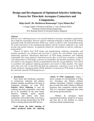
- 1. Design and Development of Optimized Selective Soldering Process for Thru-hole Aerospace Connectors and Components. Shiju Jacob1 , Dr. Hariharan Ramasangu2 , Ugra Mohan Roy3 1- (Engg) student, 2-Professor and Dean, 3- Asst. Professor (EEE) Electronic Systems Design Engineering M.S. Ramaiah School of Advanced Studies, Bangalore Abstract Selective wave soldering process is an essential method in aerospace and defence applications, due to high mix of packages. However selective soldering technology is badly hit by the airholes generated inside the plated thru-hole (PTH) area, which is called as void. Void problem spoils lot of time and money in the manufacturing industry and the research conducted so far could provide only partial solutions. An optimized solution for void problem in selective soldering is proposed here. Chances of defects from PCB design and manufacturing, soldering consumables and machine parameters are analysed and corrected to resolve the void problem using system engineering approach. Operational deficiencies of PCB design parameters and soldering consumables have been analysed. Functional process flow of void issue resolution is defined with enhancement in PCB design, selection of consumables and machine parameters design. A test vehicle is also designed with the recommendations from the concept definition. Test vehicle is assembled with optimized soldering parameters and tested in X-Ray machine. Test report shows that even with 2.4 mm PCB and thick pin components, void doesn’t occur in the PTH. Finally design for manufacturability (DFM) guideline is proposed for PCB design to eliminate the void issue caused by PCB design process. 1. Introduction Form factor and interfacing constraints in commercial, industrial and defence products mandate assembling of all types of component packages on same PCB. Selective Wave Soldering is used for soldering thru-hole components, when both are to be assembled on the same board. Selective soldering selects specific component and solders only those components with melted solder wave from a tiny nozzle moving around below the PCB which is already placed with SMT devices. Void means the holes (missing of solder) produced inside the soldering volume of PTH components. Figure 1 shows example of void identified in X-Ray test. Aerospace and defense products undergo tremendous vibration. Component pins covered with solder vibrates in different frequency than component without solder. Thus at a maximum magnitude pins crack and circuits get disconnected. Military & Aerospace board manufacturing industry spends lot of money and time due to this problem in critical electronic boards manufacturing.
- 2. Figure 1 X-Ray Image of Void 2. Selective Soldering ; a debrief Selective soldering is done with a programmable machine. PCB is fitted horizontally on a fixture with the components placed. Soldering is done with a nozzle which is moving under the PCB and chooses the components based on the program. Machine has a solder bath from which melted solder is pumped to the nozzle tip with nitrogen gas. Machine has fluxing and preheating feature to enhance the soldering performance. Figure 2 shows soldering chamber with nozzle under the PCB just before it starts the soldering. All operations in the soldering chamber is captured by a camera and displayed on the computer screen to help the calibration and alignment of the nozzle and fluxer. Figure 2 Soldering Nozzle Materials used for soldering are solder alloy and flux. Compound of Tin (Sn) and Lead (Pb) at a ratio of 63:37 is used for leaded process. Either solder wire or solder bar is used but purity of the compound is the important factor. Flux is used to remove oxides from the PCB surface and component leads. It also prevents re-oxidation prior to soldering. Importances of flux are reducing surface tension which allows solder to flow easier and create a better bond between the solder and soldering surfaces. Soldered joint is tested in X-Ray machine to verify quality is good in thru- hole. X-Ray test is very useful to detect void. 3. Proposed Solution for Void Problem Application engineers from machine vendors agree that quality issues in selective soldering are contributed not only by the process but from row material also. Reiner Z. and Christian O. concludes their research mentioning with implementation of some basic PCB design rules cost intensive and time consuming thru-hole rework can be avoided (Reiner Z. and Christian O., n.d.).Various concepts are explored and concluded that corrections required from all factors involved in the process. A process flow is drafted considering correction of parameters in PCB design & manufacturing, selection of consumables and machine parameters setting. Figure 3 shows the flowchart of proposed solution. Concept includes enhancements from all aspects studied in the concept exploration. A test vehicle is designed in which all challenges are incorporated. This test vehicle contains Thru-hole connectors with different pin thickness, no of rows, pitches. Thick PCB having more than 2.2 mm thickness.
- 3. 2 oz copper layer for duplication of internal drain Specific profile is developed on the machine with all machine parameters are set according to the test vehicle components and PCB. Test vehicle is then assembled with the specific assembly profile to verify the concept. Start of Mfg. Engg. DFM Check on PCB Verification of Components Design Optimization Selection of Consumables Soldering Trials Production Start Machine Programming Figure 3 Process Flow of Proposed Solution 4. PCB Design Optimization and DFM Major parameters of PCB which generate void are PTH plating thickness, component pins to PTH wall clearance and no of internal ground layers and overall thickness of the PCB. Figure 4 PTH Hole Dia and Plating Thickness Figure 4 shows cross section of PCB with PTH thickness and hole dia. Industry standard for the hole diameter is W = Pin diameter + 0.6 mm But the pins become tight in the hole in many thick pin components. So each componnet pin thickness assesed and extra dimaetr of 0.2 mm is provided for thik pins connectors. Plating thickness of 70 microns is used, which is sufficient to avoid the outgassing of PCB during soldering. Figure 5 PTH Design with Hole Clearance Figure 5 shows snapshot of PTH designed in Altium design software. Pin to wall air gap is the major parameter which is controlled in design. This is proposed as DFM guideline in the PCB design. Requirement of internal ground plane is unavoidable in power supply board 2.6 mm stack is used to simulate a thick PCB used in industry. Also de-burring is highly preferred in PCB manufacturing to remove the burrs after drilling and plating. 5. Consumable Selection Solder and soldering flux are major consumables used in selective soldering. Purity of solder is very important. Selection of solder is done based on chemical test conducted or based on the laboratory report from the manufacturer. Flux is very important for the process and it selection is WT
- 4. very critical. Properties of different types of fluxes available in industry are as below. Rosin-based fluxes, which use a base of isopropyl isopropanol (referred as IPA). It contains 5–20% of solids (rosin + activators). These fluxes deposit residues on the board after soldering which needs to be removed as it contaminates the board. So aggressive cleaning is mandatory after soldering. Low-solids fluxes have solids content in the range 1–5%.They may be based on rosin or synthetic colophony substitutes. Low-solids fluxes are designed to avoid post-solder cleaning. Water-soluble fluxes contain active organic acid components in an alcohol base. The residue from these fluxes needs to be removed from the circuit assembly with a water wash. So boards are cleaned in deionised water after soldering. Water-based fluxes have active acidic components which are blended with water. Depending on the concentration of active components in the mixture, these fluxes may be classified either as ‘no-clean’ or ‘clean with water’ types Flux is selected based on solubility, solid contents and activator presence. Composition of soldering alloy, PCB substrate, surface finish and PCB assembly cleaning method are other factors which influences the selection of flux. Flux with activator gives good soldering result but deposits lot of solids on the board. Water soluble flux is preferred because it is easy to clean. ALPHA NR 215 model is selected which is a no clean flux with less solids and surface tension. It has activator also. 6. Test Vehicle Design A test vehicle is designed with custom made PCB and specific thru-hole components. Connectors are selected with variation in pin diameter and pitch. Multi row connectors are also included in test vehicle, as shown in the table. Bill of Material of Test Vehicle Sl No Categor y Description Desig nator 1 Connect or Power-D(M-Series), Connector,PCBMount,5pin ,Male,40A, 1mOhm,Right Angle, Thru-Hole JS1 2 Connect or Power-D/Combo-D Connector, PCB Mount,3pin,Male,40A, 1mOhm,Right Angle, Thru- Hole JS2 3 Connect or Header,DIN41612,Double Row, 64Positions,2.54 mm Pitch, Type B,Class2,Right Angle, 300V,3A J1 4 Connect or Header, DIN 41612,Tripple Row,96 Positions,2.54 mm Pitch, Right Angle,250VAC,1A J2 5 Connect or Header, 3Rows,30 Positions,2.54 mm Pitch, Type C/3, CL2,1.5A, Male, Right Angle J3 6 Connect or SMB PCB Jack Receptacle without Standoffs,50 Ohm, Vertical, Thru-Hole JS3 7 PCB 160x100mm, 4 layer, 2.4mm, FR4 ---
- 5. PCB is designed with 2.6 mm stack, 2oz copper thickness in each layer. It has 4 layers and total dimension of 160x100 mm. Both ENIG and HASL finish are manufactured. PCB is designed with extra clearance for thick pin connectors to avoid the fillet problem during the soldering. Figure 5 3D View of Test Vehicle Figure 6 shows 3 dimensional view of test vehicle designed in Altium designer software. Thick pin and multi row connectors are selected as components. Thick pin connectors simulate temperature absorption and multi row connectors validate the challenge of dwell time deficiencies during soldering. 7. Assembly and Testing Various profiles has been analyzed. Selective soldering profile is designed based on the PCB parameters and types of components. Figure 6 shows the soldering profile used for test vehicle. Test vehicle is assembled in Pillarhouse JADE 200 MK II machine. Soldering is conducted with specifically designed machine profile of 120° C preheat for 65 seconds and dwell time of 3.5 seconds. APLHA NR 215 flux and ALPHA 63:37 leaded solder wire is used as consumables. Figure 6 Soldering Profile of Test Vehicle All components are tested under X-Ray after assembly to verify the void. It is observed that void doesn’t occur in any of the components. Figure 6 shows the test result of connector J3 in X-Ray. Figure 7 X-Ray Result of Test Vehicle - Connector J3.
- 6. 8. Conclusion Void defects from PCB design and manufacturing, soldering consumables and machine parameters are analysed and corrected to resolve the void problem using system engineering approach. Operational deficiencies of PCB design parameters and soldering consumables have been analysed. Functional process flow for resolving void issue is defined with enhancement in PCB design, selection of consumables and machine parameters design. A test vehicle is also designed with the recommendations from the concept definition. Test vehicle for void verification is assembled with optimized soldering parameters and tested in X-Ray machine. Each solder joint is verified with different machine settings and power level of X-Ray. Test report shows that even with 2.6 mm PCB and thick pin components, void doesn’t occur in the PTH. Single spot of air hole of less than one percentage is observed in one component pin, which is negligible in X- Ray test. Finally design for manufacturability (DFM) guideline is proposed for PCB design to eliminate the void issue caused by PCB design process. References Chang, S., Wang, R., Xiang, Y., Wang, P. & Shi, W., 2011 ‘Design for manufacturability of PTH solder fill in thick board with OSP finish’, In Electronic Packaging Technology and High Density Packaging (ICEPT-HDP), 2011 12th International Conference on (pp. 1- 8) IEEE. Cookson Electronics, 2005. ‘ALPHA NR- 215 No-Clean Flux’. In Technical Bulletin (pp 1-3). Echeverria, G., Santos, D., Chouta, P. and Shea, C., 2004. ‘Effect of Lead-Free assembly processing on solder joint voiding’, In IPC-JEDEC 5th International Lead-free Conference. F. Fernadez, E. Tang, F. Lu., ‘SELECTIVE SOLDERING TECHNOLOGY SELECTION’, In SMTA International Conference Proceedings (pp 1-9). Hai, T. and Wang, R., 2009, Failure analysis of (DIMM hole) solder void in lead free process used OSP coated PCB, 2009 4th International Microsystems, Packaging, Assembly and Circuits Technology Conference, IEEE (pp. 617-619). Hillman, C., Rogers, K., Dasgupta, A., Pecht, M., Dusek, R. & Lorence, B., 1999, Solder failure mechanisms in single-sided insertion-mount printed wiring boards, Circuit World, 25(3), pp.28-38. Association Connecting Electronic Industries, 2010 IPC-A-610E-2010 Acceptability of Electronic Assemblies, IPC User Manual. Kurtz ersa n.d., Smartflow 2020, viewed September 2015, from http://www.kurtzersa.com/electronic s-production-equipment/soldering- machines/selective/produkt- details/new-smartflow-2020.html Marquez, U.G., Barbini, D.C. and Szymanowski, R.A., n.d., ‘SELECTIVE SOLDERING WITH SN3. 9AG0. 6CU: PROCESS DEVELOPMENT’, In SMTA.
- 7. M.Tarr, 2014, ‘What You Always Wanted to know About Wave Soldering But were Afraid to Ask’, In Journal of The University of Bolton (pp13-14). Niemeier, J., Seliger, G. and Seutemann, J., 2006, ‘Selective Soldering with Precise Amounts of Liquid Solder’, 2006 1st Electronic System integration Technology Conference, IEEE (Vol. 1, pp. 612-616). Nordson Dage n.d., XD7500VR Jade FP, viewed September 2015, from http://www.nordson.com/en/division s/dage/products/x-ray-inspection- systems/xd7500vr-jade-fp Oláh, Z., Ruszinkó, M., Bátorfi, R. and Illyefalvi-Vitéz, Z., 2012 ‘Process parameter optimization of selective soldering’, In Design and Technology in Electronic Packaging (SIITME), 2012 IEEE 18th International Symposium for (pp. 119-124) IEEE. Pillarhouse n.d., Pillahouse Selective Soldering Machines, viewed 20 September 2015, from https://www.google.co.in/search?q=p illarhouse+jade+200+selective+solde ring+machine&espv=2&source=lnm s&tbm=isch&sa=X&ved=0ahUKEw iaiaGeyc_OAhWMNI8KHZrwChM Q_AUICCgB&biw=1242&bih=607# imgrc=0D9lIU1kMJjJ4M%3A Pillarhouse Inc., 2012, SOLDERING KEEP- OUT AREAS GUIDELINES, PCB Design Guidelines (pp 3-7). Pillarhouse Inc., 2010 HANDEX MANUAL REVISION B, Handex User Manual (pp 54-120). Zoch, R. and Ott, C., 2009, Effects of an appropriate PCB layout and soldering nozzle design on quality and cost structure in selective soldering processes, In SMTA International Conference Proceedings (pp. 1-6).