
Recommended
Recommended
More Related Content
What's hot
What's hot (19)
Similar to Shakeel thesis
Similar to Shakeel thesis (20)
Recently uploaded
Recently uploaded (20)
Shakeel thesis
- 1. “Experimental Investigation of Crack Propagation and Branching in Lightly Reinforced Concrete beams” A Dissertation Submitted by SHAKEELAHMAD BHAT ROLL NO: 17320365026 In partial fulfillment of requirements for award of Masters of technology In Construction Technology and Management Under the guidance of Er. Tarundeep Singh Department of Civil Engineering Desh Bhagat University Mandi Gobindgarh 1
- 2. 2 ACKNOWLEDGEMENT I take this opportunity to express my profound gratitude and deep regards to my guide Er. Tarundeep Singh for his exemplary guidance, monitoring and constant encouragement throughout the course of this thesis. The blessing, help and guidance given by him time to time shall carry me a long way in the journey of life on which I am about to embark. I am obliged to staff members of Department of Civil Engineering, Desh Bhagat University, Gobindgarh for valuable information provided by them in their respective fields. I am grateful for their cooperation during the period of my assignment. Lastly, I thank almighty, my parents, dear ones and friends for their constant encouragement without which assignment would not be possible. Shakeel Ahmad Bhat Roll. No. 17320365026
- 3. 3 Abstract Concrete is a quasi-brittle material that has a weak tensile strength in comparison to its compressive strength. Due to the low tensile strength of concrete, it is common to use concrete with reinforcement to carry the tensile stresses. As a consequence, the presence of reinforcement affects the crack development and crack propagation in reinforced concrete. Developing cracking evaluation methods is important for the safety assessment and renovation of existing infrastructure. An improved understanding of concrete cracking is an implicit requirement to achieve this aim. The main aim of this project is to investigate the nature of fracture in reinforced concrete. Relatively few fracture-oriented experimental studies have been conducted on reinforced concrete. An experimental investigation was therefore undertaken to explore the cracking process in lightly reinforced concrete (RC) beams and to observe the details of the localized fracture process zone development. More specifically, the aim was to observe the effect of beam depth (150 mm and200 mm) and steel reinforcement ratio (0.25-0.6%) on ductility through the investigation of crack branching. A total of six beams were cast in two series of two sizes (depths of 150 and 200 mm and lengths of 1000mm and 1200 mm respectively) keeping the width same (100 mm) for all the beams Each of the series includes one unreinforced and two reinforced beams. Furthermore the testing of samples is under process and after successful completion of tests a conclusion will be drawn and a relationship will also be set out for future use.
- 4. 4 CONTENTS Chapter 1………………………………………………………………………………… INTRODUCTION….…………………………………………………………………….. 1.1 GENERAL…………………………………………………………………………… 1.2 BACKGROUND AND SCOPE……………………………………………………… 1.3 OBJECTIVE…………………………………………………………………………. Chapter 2………………………………………………………………………………… LITERATURE REVIEW…………………………………………………………………… Chapter 3……………………………………………………………………………………. 3.2 METHODOLOGY IN DETAIL……………………………………………………… Chapter 4…………………………………………………………………………………… EXPERIMENTAL INVESTIGATION……………………………………………………. 1. MATERIAL PROPERTIE 1. CEMENT 2. GRADATION OF FINE AGGREGATES. 17 3. CONCRETE MIX... 4. REINFORCEMENT STEEL 5. DETAILING OF REINFORCEMENT IN BEAMSs 6. FORMWORK FOR BEAMS 7. EXPERIMENTAL SETUP 8. CRACK DETECTION MICROSCOPE.
- 5. 5 List of Figures Fig.1.1 :( a) fracture process zone (b) closure stresses (e) cracks in concrete (courtesy; Fracture mechanics by E.E Gdoutous) Fig.1.2: Flexure crack of beam. Fig.4. 1: Gradation curve of sand obtained from sieve analysis in lab. Fig.4. 2: Cube failure under compression test. Fig.4. 3: (a) Steel test specimen tested in UTM (b) Steel test specimen after failure. Fig.4. 4: Reinforcement steel used in beam. Fig.4. 5: Moulds for beams. Fig.4. 6: Insulation foam at center for notch provision. Fig.4. 7: Casting of beams. Fig.4. 8: Test specimen layout. Fig.4. 9: Test set up of Three Point Loading frame. Fig.4. 10: Crack detection microscope. Fig.4.11: Flexure crack seen through crack microscope. List of Tables Table 4.1: Readings for standard consistency test. Table 4.2: Sieve analysis of sand. Table 4.3: Sieve Analysis of Coarse Aggregate. Table 4.4: Concrete mix (M 30) Table 4.5: Cube strength under compression tests. Table 4.6: Tensile strength of reinforcing steel bar. Table 4.7: Details of test specimens.
- 6. 6 Chapter I INTRODUCTION 1.1 GENERAL Concrete is a quasi-brittle material that has a relatively weak tensile strength when compared with its compressive strength. It is therefore susceptible to cracking. The cracking process in concrete is complex because the crack itself is a partially damaged zone with some capability for stress-transfer in the fracture process zone (FPZ). The FPZ acts as a transition zone between the discontinuous open crack and the continuous intact material beyond the crack. Although there is some debate about what constitutes a FPZ, and the size of the FPZ, there is a general agreement that it exists in concrete [1]. A realistic description of the FPZ is essential in order to understand damage mechanism and to predict and optimize the behavior of concrete structures. In reinforced concrete, the fracture process is further complicated by the presence of the reinforcement that affects the crack development and propagation. The cracking process is associated with diverse phenomena such as the formation of cracks, crack propagation, the existence of micro-cracks, interactions between the reinforcement and concrete, and the concrete microstructure e.g. cement and aggregate [2]. In addition, numerous factors can influence the cracking process and reinforcement crack bridging including the concrete compressive strength the type, the properties and the ratio of the longitudinal reinforcement, the bond between the reinforcement and the concrete, and the geometrical properties and the size of the beam. These factors can be inter-related and inter-dependent. Furthermore, the cracking process in reinforced concrete (RC) may involve several macro-cracks propagating at the same time leading to different failure modes. Internal reinforcement bridges a crack and improves the fracture toughness by providing a stitching action that prevents the crack faces from opening and controls the crack growth by increasing the energy demand for crack advancement [3]. The fracture energy is closely related to the FPZ size and this implies that the existence of a FPZ may be the intrinsic cause for size effects. In concrete the FPZ covers a narrow crack band and only the region along the crack path is affected by cracking [4]. However, in reinforced concrete the nature of the FPZ remains unclear. Most theoretical studies incorporate the reinforcement according to the principle of superposition by
- 7. 7 considering concrete fracture and adding the effect of the reinforcement as a closing force [5]. Although the fracture properties of reinforced concrete at the structural scale have been studied, there is a need for further detailed investigations to better understand the nature of the fracture process Understanding cracking in reinforced concrete is important for the strength assessment and renovation of existing structures. Relatively few fracture-oriented experimental studies have been conducted on concrete with internal steel reinforcement. Knowledge of concrete fracture processes can help identify suitable analytical approaches that capture the details of the crack process. This study presents an experimental investigation of RC beams subjected to three point bending. A particular focus is the localized zone around the crack and the crack branching phenomena. Crack branching is a toughening mechanism in quasi-brittle materials and can be a source of size effects. Yet it has received little or no attention when studying the fracture of RC beams. In reinforced concrete, the confinement provided by the reinforcement to the crack path increases the possibility of crack branching. The crack branching that takes places during the failure process makes the failure behavior more ductile. The aim of this project is to experimentally determine the relationship between size, reinforcement ratio and ductility through investigation of crack branching in RC beams. Although more experiments are required to generalize the results, this project acts as a foundation to describe the flexural behavior of lightly reinforced concrete beams and for further investigations of RC fracture processes. 1.2 BACKGROUND AND SCOPE Over the past decades various studies were conducted to investigate concrete cracking and models were developed to simulate the cracking process in reinforced concrete beams. These models can broadly be classified as either plasticity-based models which are justified in the case of ductile behavior e.g. beams with sufficient internal steel, or fracture mechanics-based models which do not treat fracture as a point phenomenon but use fracture mechanics principles to explain crack propagation. The cracking process in concrete is complicated because it is associated with the development of minor cracks and micro cracks as well as macro-cracks Cracking is also connected with other phenomena such as strain localization and bridging. In a traditional strength criterion analysis, the behavior is described using continuum variables of stress and strain. However, during fracture propagation the behavior depends on what is happening in the fracture process zone (FPZ) ahead of the crack tip, which is a partially damaged zone with some residual ability to transfer stress.
- 8. 8 1.3. OBJECTIVES This project aims to carry out an in-depth investigation of the crack propagation RCC beams. This will be achieved through experimental work which is required to observe the true cracking behavior in RC beams. More specifically, the objectives of this project are: To study the effect of reinforcement on the crack propagation in concrete beams To observe the effect of beam depths on relative depth of crack branching. To study the effect of both beam depth and reinforcement on the ductility of RCC beams through investigation of crack branching. To see the relation between the relative depth of crack branching and ductility.
- 9. 9 Chapter 2 LITERATURE REVIEW Skarzynski and Tejehman [9] tested small RC beams with a height of 80 mm and length 320 mm (effective length 240 mm) with a reinforcement ratio of 1.5%. It was found that the localized zones are always created prior to the attainment of the peak load and the lengths of the fracture zones in RC beams (0.8 of the beam height) are higher than those in unreinforced concrete beams (0.6 of the beam height). Alam et al. [10] used Acoustic Emission (AE) to study microcracking in RC beams. It was found that as the beam size increases, the fracture process changes from tensile-microcracking macrocracking to shear-compression macrocracking. Digital image correlation has also been used to study the cracking in reinforced concrete beams failing in shear and it was found that the observed size effect was in agreement with Bazant's size effect [I. Annette Beedholm, Jakob Fiskera, Lars German |12] proposed an approach for predicting crack systems, and more importantly crack widths in beams from the experimental observations of the crack pattern in flexural members investigated by Sherwood. The approach assumes the initial existence of flexural cracks the spacing between which is estimated by a simple empirical relation proposed by Reinbeck. For a certain configuration of the depth, cover, reinforcement ratio etc. secondary cracks are allowed to develop in between the flexural cracks. The theoretical results show that the spacing between the flexural cracks shows a linear proportionality to the effective depth of the member with only a minor variation with respect to the reinforcement ratio, neglect able for beams with an effective depth smaller than about 800mm. This is supported by the experimental observations. On the contrary, the secondary cracks indicate no apparent dependency of the variation in effective depth. When comparing the results of the estimated crack widths to the measurements that approach it is seen to precisely reproduce the observed size effect in terms of the relative increase. With respect to the absolute values of the estimated crack widths a fairly good agreement is also seen.
- 10. 10 N.A.B. Yehia [13] has done experimental testing of 9 notched reinforced concrete specimens under four point bending. The beams comprise three beam sizes and three tension reinforcing steel ratios. All beams have constant span/depth ratio of 4, initial notch/depth ratio of 03. Two strengthening fiber laminates were used: Glass fiber for the two lower tension reinforcing steel ratios and Carbon fiber for the higher tension reinforcing steel ratio. The strengthening laminates were designed to enhance beam moment capacity by 15% to 150% depending on the beam size and reinforcement ratio. To simulate real life strengthening situations, beams were first loaded until the notch propagated to 0.5 the beam depth. The strengthening fiber laminate was then introduced to the tension side of the beam while the load was kept applied to the other side of the beam. The fracture moment for a given crack depth was calculated through an analytical algorithm which employs Linear Elastic Fracture Mechanics. The approach takes into consideration the previous loading history of the beam prior to introducing the strengthening laminate. Test measurements of crack extension and applied load were used to compare the fracture moment recorded experimentally to that one calculated analytically. The application of the solution algorithm to different specimen sizes cross-section dimensions, reinforcement ratio, and strengthening fiber laminate showed that the solution algorithm is able to effectively predict the behavior of larger beam size and/or reinforcement better than that of smaller beam size and/or reinforcement. A sensitivity analysis was conducted to explore this point. C. Barris et al. [14] have studied the cracking behavior of GFRP RC elements based on the results of an experimental program involving 15 beams. The paper studies the influence of the reinforcing material, concrete cover, stirrup spacing and bond between the concrete and the reinforcement. For this purpose, two different types of GFRP and steel bars were used. The cracking behaviour (erack width and spacing) in the pure bending zone was analysed up to the service load. Crack width was consistently acquired by using a Digital Image Correlation (DIC technique. The 2D full-field displacements of the pure flexural zone were registered using 4 digital cameras and commercial software that enables the evolution of the specimen cracks to be analysed. Finally, bond coefficients have been adjusted to different formulations in terms of crack spacing and crack width.
- 11. 11 2. METHODOLOGY IN DETAIL LITERATURE REVIEW Comprehensive study of various parameters was done after the selection of topic. Previous studies, codal provisions, recent advancement and future scope were considered before the project work (practical work) was to be commenced. COLLECTION OF MATERIAL This step involved procurement of the materials required for construction of beam samples viz. Cement Fine aggregates Coarse aggregates Steel bars Formwork board The instruments for testing of samples involved: Dial gauges Crack detection microscope High resolution digital camera Loading setup TESTING OF MATERIALS The materials were tested in order to authenticate the quality of material to be used for casting the tests involve physical tests for cement, fine aggregates and coarse aggregates. FABRICATION OF BEAMS A total of six unreinforced and reinforced concrete beams of two dimensions were cast under similar environmental conditions Out of six beams, the two unreinforced beams were set as
- 12. 12 reference beams to obtain an exact benchmark for comparison. The specifications of the beams and the percentage of steel reinforcement in each sample are as under: Sample 1: Reference (control) beam of dimensions 100 mm x 150 mm x 1000 mm Sample 2: Reference beam of dimensions 100 mm x 200mm x 1200mm Sample 3: Reinforced beam of same dimensions as that of sample 1 with reinforcement of 0.3% . Sample 4: Reinforced beam of same dimensions as that of sample I with reinforcement of 0.6% Sample S: Reinforced beam of same dimensions as that of sample 2 with reinforcement of 0.25% Sample 6: Reinforced beam of same dimensions as that of sample 2 with reinforcement of 0.5% .TESTING OF BEAMS Each beam was tested to failure under three-point loading. The beams were made to rest on bearing pads of width 10 cm at the ends which in turn were rested on supports. This was done to simulate the simply supported conditions as closely as possible. TEST RESULTS AND DISCUSSION This includes the analysis to observe the effect of depth and reinforcement on crack propagation in concrete, strength and ductility. INTERPRETATION OF RESULTS Effect of reinforcement on crack propagation is reflected through branching of cracks at different Percentage of reinforcement. Crack branching is a cause for increase in ductility of beams. CONCLUSION This involves brief overview of the data analysis and interpretations. This chapter rounds up the Whole project and also contains the highlights of the project.
- 13. 13 Chapter 4 EXPERIMENTAL INVESTIGATION 1. MATERIAL PROPERTIES Testing of materials was done in order to authenticate the quality of material to be used for casting. Testing of materials involve physical tests for cement, fine aggregates, and coarse aggregates. 1. CEMENT The cement used was ordinary Portland cement of grade 43. To determine the properties of cement several tests were conducted which are as follows. STANDARD CONSISTENCY Standard consistency of a cement paste is defined as the water content at which the paste will permit a Vicar’s plunger having 10 mm dia and 50 mm length to penetrate to a depth of 33-35 mm from the top of the mould. The test is useful for finding out initial setting time, final setting time, etc. The standard consistency was found to be 30 %. Table 4. I: Readings for standard consistency test Trial No. Water-cement ratio Penetration of plunger (mm) 1 0.25 16 2 0.27 27 3 0.29 32 4 0.295 33.4 5 0.30 34
- 14. 14 INITIAL SETTING TIME OF CEMENT Initial setting time of cement is regarded as the time elapsed between the moment when water is added to the cement to the time when the paste starts losing its plasticity. Using vicat's apparatus, it is measured as the period elapsed between the moment when water is added to the cement and the time when the needle (I mm dia) penetrates the test mould to a depth of 33-35 mm from the top at water content of 0.85 times the standard consistency. The observations obtained are as under Weight of water 400 g Weight of water-0.85 *30/100*400 102g Initial setting time is obtained as 3 hours 10 minutes. FINAL SETTING TIME OF CEMENT The final setting time is the time elapsed between the moment the water is added to the cement and the time when the paste has completely lost its plasticity and has attained sufficient firmness to resist certain definite pressure. In vicat’s apparatus, it is the time elapsed between the moment when water is added to the cement and the time when the center needle makes an impression not more than 0.5 mm deep while the circular cutting edge of the attachment fails to do so. The final setting time was observed as 5 hours 40 minutes. 4.1.2 GRADATION OF FINE AGGREGATES Weight of sample taken 1500 g Sieves required 4.75 mm 2.36 mm 1.18 mm 600H -300u and 150
- 15. Table 4.2 Sieve analysis of sand Sieve size Weight retained (g) % wt. Retained Cumulative % wt. retained % finer Remarks 4.75 mm 3 0.2 0.2 99.8 Sand falls in zone ΙΙ 2.36 mm 11 0.733 0.933 99.06 1.18 mm 80.5 5.36 6.293 93.70 600µ 747.5 49.8 56.09 43.91 300µ 598 39.86 95.95 4.05 150µ 50.5 3.36 99.31 0.69 As the percentage passing through 600 µ sieve is between 35 and 59, the sand tested belongs to gradation zone ΙΙ. -20 Cumulative %age Passing vs. Particle size. Fig.4.1 gradation curve of sand obtained by sieve analysis From the gradation curve we find D10 = 0.33, D30 = 0.48, D60 = 0.72 Cu = D60/D10 = 0.72/0.33 = 2.18 Cc = D30 2/(D10 x D60 ) = 0.482/(0.33 x 0.72) =2.02 Thus the sand is poorly graded sand. 20 0 120 100 80 60 40 0 1 2 3 4 5 Gradation curve 15
- 16. 16 COARSE AGGREGATES The coarse aggregates used were crushed stone aggregates. The coarse aggregates of two grades were used one retained on 10 mm sieve and another grade contained aggregates retained on 20 mm size sieve. The maximum size of coarse aggregate was 20 mm having specific gravity of 2.88 grading confirming to IS: 383-1970. Table 4. 3: Sieve Analysis of Coarse Aggregate Description of sample Specific gravity Grading Remarks % passing Coarse aggregates 20 mm :10 mm::60:40% 2.88 Sieve designation (mm) Conforms to 20 mm full graded coarse aggregates as per IS:383- Obtained Required by weight 1970 specifications40 100 100 20 95 100-95 10 32 25-55 4.75 0 0-10 4.1.3 CONCRETE MIX The concrete mix used was M30 which was designed as per IS 10262-2010. The proportion of ingredients of concrete required for the design mix was calculated as:
- 17. 17 Table 4. 4: Concrete mix (M 30) material Mass required per m3 (kg) Cement 330 Water 210 Sand 780 Aggregate 1025 TESTING OF CONCRETE CUBES Three concrete cubes were cast simultaneously with the beam samples using design mix M30 in order to verify the quality of material and mixing apparatus. The cubes were properly cured and testing was done after 28 days. The following results were obtained Table 4.5: Cube strength under compression test Sample no. Compressive strength (N/mm2) 1 32.4 2 35.6 3 31.8
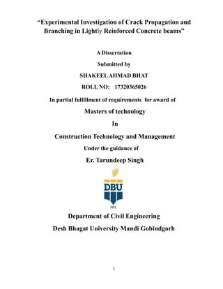
- 18. Fig,4.2: Cube failure under compression test 4.1.4 REINFORCEMENT STEEL The reinforcement steel used in concrete beams was High-Yield Strength Deformed (HYSD) bars confirming to IS 1786:1985. The yield strength of steel reinforcements used in the experimental program was determined by performing the standard tensile test on the three specimens of each bar. The proof stress or yield strength of the specimens are averaged and shown in Table 4.6. The modulus of elasticity of steel bars was 2 x 10⁵ MPa. The reinforcement involved only steel bars of f6mm and 8mm diameter which were bended later at the two ends at right angles up to 10 cm length. The steel bars were used as a flexural reinforcement only. 18
- 19. Table 4.6: Tensile strength of reinforcing steel bars Sample Dia of bars (mm) 0.2% proof stress (N/mm2) Average proof stress (N/mm2) 1 8 520 523 2 8 527 3 8 521 4 6 531 5285 6 525 6 6 528 (a) (b) Fig. 4.3: (a) Steel test specimen tested in UTM (b) Steel test specimen after failure 19
- 20. 4.1.5 DETAILING OF REINFORCEMENT IN BEAMS The steel reinforcent bars used in concrete beams were bended at right angles at the ends, these bars were used as flexural reinforcement only and shear reinforcement was not provided. The steel reinforcement included the HYSD steel bars of diameters 6mm and 8 mm. Fig. 4.4: Reinforcement steel used in beams 20
- 21. 4.1.6 FORMWORK FOR BEAMS The plywood sheets were sawn in the carpentry shop to form the sheets of required sizes. These small sheets were joined to form the moulds for beams. Fig.4.5: Moulds for beams Fig.4.6: Insulation foam at center for notch provision 21
- 22. 4.1.6 CASTING OF BEAMS To cast the beams, the mould for each specimen was held in position with help of side supports. At the centre of each mould, insulation foam of thickness 6 mm and depths of 20 mm and 25 mm was provided in beams of depth 150 mm and 200 mm respectively, to serve the function of notch. The notch was provided to ensure that the flexural cracks occur in beams starting from the notch. After this, the concrete was made in a mixer and placed in the moulds. In case of reinforced samples clear cover of 20 mm was provided and to ensure this cover, a layer of plain concrete of thickness 20 mm in case of beam depth of 150 mm and 25 mm in case of beam depth of 200 mm was laid initially on which the steel bars were rested to act as flexural reinforcement. As no shear links were used, the flexural steel bars were held fixed until the concreting was completed flush with the top surface. The compaction of concrete was done by using needle vibrator. Fig. 4.7: Casting of beams 22
- 23. 23 Table 4. 7: Details of test specimens Concrete cube comp. strength (Mpa) Beams dimension B X D X L (mm) Reinforcement ratio Notation M 30 100 x 150 x 1000 Unreinforced (0%) M30,D150,0% 2T6 (0.3%) M30,D150,0.3% 2T8 (0.6%) M30,D150,0.6% 100 x 200 x 1200 Unreinforced (0%) M30,D200,0% 2T6 (0.25%) M30,D200,0.25% 2 T8 (0.5%) M30,D200,0.5% A crack inducer was located at mid-span. Insulation foam was used to form the crack inducer where the foam was cut into pieces with a width of 6 mm and depth of 20 mm for the beams of dimensions 100*150* 1000 mm and width of 6mm and depth 25 mm for beams of length 100*200 1200 mm. The foam was inserted vertically at the middle of the formwork prior to casting. As no shear reinforcement is provided, the notch has been provided to ensure that flexural cracks occur starting from the notch.
- 24. 24 Remaining course of action As the casting of beams ended, the beams will be tested under three point loading system and the Flexure behavior, Ductility factor, Crack propagation and branching of lightly reinforced concrete beams of different dimensions and varying percentage of reinforcement with respect to unreinforced concrete reference beams of similar dimensions will be studied. The impact of varying size of beam on the pattern and propagation of flexure crack will be studied and the contribution of reinforcement on reduction of these flexure cracks will be of prime motive and if exists, a relationship will be framed between the percentage of reinforcement and crack reduction.
- 25. 25 REFERENCES [l] Mindess S. "The fracture process zone in concrete". In: Shah S, editor. "Toughening mechanism of quasi-brittle matter". Dordrecht: Springer, Netherlands; 1991, p.271-8 [2l Hillerborg A, Modéer M, Petersson PE. "Analysis of crack formation and crack growth in concrete by means of fracture mechanics and finite elements”.Cem Concr Res 1976;6:773-81 3Carpinteri A, Massabo R. "Contimuous vs discontiuous bridged-crack model for fireinforced materials in flexure". Int J Solids Struct 1997:34:2321-38 4Wu Z Rong H, Zheng J, Xu F, Dong W, "An experimental investigation on the FPZ properties in concrete using digital image correlation technique”. Eng Fract Mech 2011:78:2978-90. 5 Carpinteri A. "Stability of fracturing process in RC beams". J Struct Eng 1984;110:544-58. 6 Vegt I, Breugel V, Weerheijm J. "Faiture mechanisms of concrete under impact loading" Fract. Mech. Concr. Concr. Struct. Fram., 2007, p. 579-87 7 Beeteeo V. "Ductility based structural design". In: Proc. Ninth World Conf. Earthq. Eng. Tokyo-Kyoto, Japan, Tokyo-Kyoto, Japan; 1988 8Park R. “Evaluation of ductility of structures and structural assemblages from laboratory testing". Bull NZ Natl Soc Earthq. Eng 1989; 22:155-66 9Skarzynski L, Syroka E, Tejchman J. "Measurements and calculations of the width of the fracture process zones on the surface of notched concrete beams". Strain 2011:47:319-32. 10Alam SY, Loukili A, Grondin F, Rozière E. "Use of the digital inage correlation and acoustic emission technique to study the effect of structural size on cracking of reinforced concrete. " Eng Fract Mech 2015;143:17-31