SlideShare a Scribd company logo
1 of 36
Download to read offline
SAP 940002164 - December 2022
www.schiedel.com/uk
ICID Plus
100-200mm Diameter Range
Twin Wall Insulated System Chimney
for Gas, Oil, Wood and Multi-fuel
DON'T FORGET TO REGISTER YOUR INSTALLATIONS
AND START EARNING SCHIEDEL INSTALLER REWARDS
See inside for more details
LIFETIME *
GUARANTEE!
Download the
Augmented
Reality
Chimney
Builder App
for an instant quote!
2
Twist-lock bayonet jointing system. Secured by locking
band.
Advanced corrosion resistant design and construction uses
laser welded 316L stainless steel inner liner and stainless
steel case.
The 25mm of high density mineral wool insulation
maintains flue gas temperature, maximising efficiency,
improving flue draught on start up and minimising
condensation.
Low external case temperature.
The inner liner is free to expand through the female collar,
allowing for maximum thermal expansion even during a soot
fire.
The inner liner has an engineered design with an inward
bead at the female end which acts as a capillary break
preventing moisture being drawn through the joint.
Lip seal packs are available containing a quick fit female
lip seal with a grease sachet to allow product to be easily
adapted for use in Positive Pressure (P) applications for use
on condensing positive pressure appliances.
Product Description
Our ICID range has evolved into a multi-application system
adaptable for Dry (D), Fu (W) and even Positive Pressure (P)
applications.
At Schiedel, we pride ourselves on our technology and
innovation and this heating season introduce our evolutionary
3-in-1 system:
ICID Plus Ideal not only for traditional stoves but also for
pellet stoves, biomass appliances, mini/micro CHP and even
condensing boilers capable of withstanding positive pressure.
The system is designed so that the outer case is load bearing
and the inner liner is free to expand independently, therefore
thermal expansion is accommodated within each and every joint
of the system.
Available in two versions with a choice of either a bright
annealed or a matt black painted stainless steel outer case,
ICID Plus is available in the following range of diameters:- 100,
125, 150, 180 and 200mm.
Front cover image courtesy of Charlotte Smith from St. Mary's
Space showing an ICID system installed by Backwoodsman.
ICID PLUS PRODUCT FEATURES
Joint Design
WITHOUT LIP SEAL
ICID Plus for N rated Negative
Pressure Applications
(i.e. Stoves)
WITH LIP SEAL
ICID Plus for P rated Positive
Pressure Applications
(i.e. Condensing Boilers)
YELLOW PARAFFIN WAX
DO NOT SWALLOW
YELLO
W
PA
RA
FFIN
W
A
X
DO
N
OT
SW
A
LLO
W
Male Collar
Male Spigot
Lubricant
Female
Lip Seal
Inward Bead
Please note that an updated version of this brochure is always available online https://www.schiedel.com/uk/brochures
3
System Chimney EN1856-1
T450 N1 W V2 L50050 G60
T450 N1 D V3 L50050 G60
60mm Distance to combustibles
running through a combustible floor
using G60 round firestop
T450 N1 W V2 L50050 G50
T450 N1 D V3 L50050 G50
50mm Distance to combustibles
a) running through a combustible floor using G50
ventilated fire stops
b) In a ventilated shaft using G50 or G60 round
ventilated fire stops in combination with G50
ventilated support plate at base and G50 ventilated
fire stop plate at top of shaft.
c) In free air
T200 P1 W V2 L50050 O00
Zero distance to combustibles*
Connecting Flue Pipe EN1856-2
T450 N1 D V2 L50050 G100 M
Approvals
ICID is CE Certified to EN1856-1 TÜV 0036 CPR 9195 010 with designations:
ICID is CE Certified to EN1856-2 TÜV 0036 CPR 9195 042 with designations:
• Manufactured under a Quality Management Scheme approved to BS EN ISO 9001
• 4 Hour Fire Rating to BS476 Part 20
• Certified for corrosion resistance on gas, oil and solid fuel by Gastec, MPA and TÜV
• HETAS listed for use on solid fuel applications.
CHIMNEY DIAMETER
The chimney size should be as recommended by the appliance
manufacturer. Where there is a requirement for a flue
diameter smaller than the appliance spigot, then the operational
requirements of the appliance and the configuration of the flue
must satisfy the flue sizing requirements of EN13384-1 for single
appliances, and EN13384-2 for multi appliances.
CORROSION RESISTANCE
Chimneys are subject to significant corrosion attack by flue gas
condensates, particularly from solid fuel. ICID Plus is specifically
designed and manufactured to resist this corrosion.
Technical Data
* For full information refer to p.22 and p.24
ICID (without Lip Seal) ICID Plus (with Lip Seal)
Fuel Wood, solid fuel Gas, Oil
Firing Temp 450°C 200°C
Short Firing Temp 550°C 250°C
Thermal Shock 1000°C -
Mode of Operation Zero & Negative Pressure Positive Pressure
Pressure Capabilities 40Pa 200Pa
Fire Rating 4 Hour Fire Rating to BS 476 Part 20
Outer Case (Standard) Stainless Steel
Outer Case (Option) Painted matt black
Outer Case Thickness 0.5mm
Seam Laser or inert gas welded
Liner 316L : 1.4404 : X2CrNiMo 17-12-2
Liner Thickness (mm) 0.5mm
Seam Laser or inert gas welded
Insulation High performance mineral fibre
Insulation Thickness 25mm
Average Thermal Resistance (200°C) 0.4m2 k/W
4
Typical Installations for
Solid Fuel Applications
INTERNAL HOUSE
Combustible Floors
Raincap (without mesh)
Angled Flashing
Roof Support
Ventilated Firestop Plate
Ventilated Support Plate
Combustible floor
Ventilated Firestop Plate
Combustible floor Plate
SW-DW Stove Pipe
Starter Section
Prima Smooth
Connecting Flue Pipe
Combustible shaft
Protective wire mesh
(required in loft space)
INTERNAL HOUSE
Non Combustible Floors
Taper Terminal
Storm Collar
Uni-flash
Roof Support
Firestop Plate
Support Plate
Non combustible floor
Firestop Plate
Non combustible floor
Adjustable Pipe
Anchor Plate
Non combustible shaft
Protective wire mesh
(required in loft space)
5
Typical Installations for
Solid Fuel Applications
Typical Installations
EXTERNAL
System Chimney
Taper Terminal
Structural Wall
Band
Structural Wall
Band
Structural Wall Band
Extension
45˚ Bend
Adjustable Top Plate
Cantilever Support
135˚ Tee
Mitred Wall Sleeve 45˚
INTERNAL BUNGALOW (VENTILATED LOFT SPACE)
Combustible and Non-Combustible floors
Raincap (with sparkguard)
Angled Flashing
Roof Support
Prima Smooth
Connecting Flue Pipe
Protective wire mesh
(required in loft space)
Round Bungalow
Firestop Kit (unventilated)
SW-DW Stove Pipe
Starter Section
TYPICAL CONDENSING BOILER
INSTALLATION
Tapered Terminal
Pipe
Wall Band
Wall Band
93˚ Tee
Wall Support
Tee Plug
with Drain
Ceiling Hanger
93˚ Reducing Tee
Appliance Connector
Offset Drain
Adjustable Pipe
Adjustable Pipe
TYPICAL BIOMASS INSTALLATION
Tapered Terminal
1000mm Pipe
Angled
Flashing
135˚ Tee
Inspection Tee
Wall Support
Tee Plug
with Drain
Schiedel
Rite-Vent
Prima Plus
Structural Locking
Band
Roof Support
Wall Band
500mm Pipe
45˚ Elbow
Prima Plus
to ICID Plus
6
Gasket kits
(for use in P rated positive pressure applications)
Finish
Paint - ICID Plus can be supplied painted in any RAL colour (additional costs apply).
The standard finish for ICID Plus is satin. The option of a matt finish is available on request.
Dimensions
Female Viton Lip Seal Kit
Int Ømm 100 125 150 180 200
Ext Ømm 150 180 200 230 250
SAP Code 147322 147323 147324 147325 147326
This female lip seal must be used on wet positive pressure applications and fits
into the inward bead on the female socket on the inside of the liner immediately below the male collar.
Adjustable Pipe Seal Kit
Int Ømm 100 125 150 180 200
Ext Ømm 150 180 200 230 250
SAP Code 152135 152136 152137 152138 152139
This kit consists of a female viton seal which fits into the inward bead on the female socket on the inside of the liner immediately below the male collar
and a male viton lip seal which must be fitted into the inward bead of the liner, which is situated in the top half of the 2-piece adjustable pipe, and at
the bottom of the liner on the 1-piece adjustable pipe.
The dimensions of the flue are:
Int Ømm 100 125 150 180 200
Ext Ømm 150 180 200 235 256
7
SW - DW Connector (Open) DN8A047
Int Ømm 125 150 180 200
Ext Ømm 180 200 235 256
This component MUST only be fitted to stove pipe and NOT directly to appliance.
SAP Code Plain 125307 126082 126827 127410
SAP Code Black 125308 126079
SW - DW Connector (Closed) DN8A144
Int Ømm 100 125 150 180 200
Ext Ømm 150 180 200 235 256
A 97 123 148 177 198
This component MUST only be fitted to stove pipe and NOT directly to appliance.
SAP Code Plain 147329 125287 126060 126810 127393
SAP Code Black 147330 125288 126059 COA COA
Uninsulated Increasing Adaptor (SW - DW) DN8A143
Int Ømm 100 125 150 180 200
Ext Ømm 150 180 200 235 256
A - 98 123 148 178
SAP Code Plain - 125320 125321 COA COA
SAP Code Black - 144439 125319 COA COA
* used on appliances with rear outlet
Insulated Appliance Connector
Int Ømm 100 125 150 180 200
Ext Ømm 150 180 200 235 256
A 97 123 148 177 198
SAP Code Plain - 146418 146419 146420 146421
SAP Code Black - 146414 146415 146416 146417
Insulated Increasing Adaptor DN8A136
Int Ømm 125 150 180 200
Ext Ømm 180 200 235 256
A 98 123 148 178
B 100 118 116 116
C 50 50 50 50
SAP Code Plain 125305 126077 126824 127408
SAP Code Black 144438 126078 COA COA
Starting Components
A
Int Ø
B
C
A
Int Ø
35
30
Int Ø
100
Int Ø
A
97
Ext Ø
A
77
Insulated Adaptor for Sirius Stove
Int Ømm 125
Ext Ømm 180
SAP Code Plain 176051
SAP Code Black 176052
Int Ø
131
8
A
Prima
Smooth
97
Int Ø
A
Prima
Plus
1037
172
290
Int Ø
Ext Ø
Int Ø
Ext Ø
Starting Components
Adaptor Prima Smooth to ICID Plus (Dry Applications only) PS027
Int Ømm 125 150 180 200
Ext Ømm 180 200 235 256
SAP Code Plain 109992 110270 126981 127588
SAP Code Black 109991 110268 126980 127587
This component MUST only be fitted to stove pipe and NOT directly to appliance.
Double Wall Adjustable Starter Section (1037mm)
Int Ømm 100 125 150 180 200
Ext Ømm 150 180 200 235 256
SAP Code Plain - 149644 149645 - 149647
SAP Code Black - 149648 149649 - -
Double Wall Adjustable Starter Section (600mm)
Int Ømm 100 125 150 180 200
Ext Ømm 150 180 200 235 256
SAP Code Plain - 152214 152215 - 152217
SAP Code Black - 152218 152219 - -
Adaptor ICID Plus to Prima Plus DN8A113
Int Ømm 100 125 150 180 200
Ext Ømm 150 180 200 235 256
A 132 132 132 134 134
SAP Code Plain 147331 125292 126062 126813 127396
Adaptor ICID Plus to Prima Smooth (Dry Applications only)
Int Ømm 125 150 180 200
Ext Ømm 180 200 235 256
A 132 132 134 134
SAP Code Plain 145516 145517 145518 145519
Black painted Starting Components are finished using high temperature paint | COA : Code on application
Adaptor Prima Plus to ICID Plus S027
Int Ømm 125 150
Ext Ømm 180 200
A 130 150
SAP Code Plain 125688 126278
This component MUST only be fitted to stove pipe and NOT directly to appliance.
50
Int Ø
A
Int Ø
Ext Ø
Sirius Stove Double Wall Adjustable Starter Section (600mm)
Int Ømm 125
Ext Ømm 180
SAP Code Black 175710
9
A Ø
1066
40
42
C Ø
A
B
72
Flex Ø
A
B
A Ø
352*
100
Starting Components
Anchor Plate (Dry Applications only) DN8A0D6
Int Ømm 100 125 150 180 200
Ext Ømm 150 180 200 235 256
A 250 300 320 355 375
B 270 280 300 335 356
C 97 123 148 178 198
Flex Ømm 125 125 155 180 200
SAP Code Plain - 125300* 126072* 126774* 127344*
SAP Code Flex 147336 142587 142595 142589 142590
SAP Code Black 147337 142591 142596 142593 142594
SW-DW Adjustable Starter Section (Short) (Dry Applications only)
Increasing SW-DW Adjustable Starter Section* (Short) (Dry Applications only)
DN8A159
DN8A161
Int Ømm 125 125* 150 180 200
Ext Ømm 180 200 200 235 256
A 123 123 148 178 198
B 352 434 352 352 352
SAP Code Plain 125340 126096 126118 126850 127435
SAP Code Black 125339 131148 126117 126849 127434
This component MUST only be fitted to stove pipe and NOT directly to appliance.
SW-DW Adjustable Starter Section (Long) (Dry Applications only)
Int Ømm 125 150
Ext Ømm 180 200
A 123 148
B 1066 1066
SAP Code Plain 148503 148504
SAP Code Black 148507 148508
This component MUST only be fitted to stove pipe and NOT directly to appliance.
Black painted Starting Components are finished using high temperature paint | COA : Code on application
Screwfit adaptor from ICID Plus to TecnoFlex Plus
Int Ømm 100 125 150 150 180 200
Flex Ømm 100 125 150 155 180 200
SAP Code Plain 174081 174082 174083 174084 174085 174086
Flex Ømm
Nom Ømm
128
A Ø
352
100
UE to ICID Adjustable Starter Section
Int Ømm 125 150
Ext Ømm 180 200
A 123 152
B 147 172
SAP Code Plain 175405 175406
SAP Code Black 175408 175409
B Ø
10
Pipes
A
40
Eff.
Adjustment
NOTE: Black product MUST not be connected directly to the stove.
Refer to stove starting components
40
A
40
A
40
A
40
A
40
A
1460mm Pipe (1454mm Effective Length) DN8A128
Int Ømm 100 125 150 180 200
Ext Ømm 150 180 200 238 256
A 1454 1454 1454 1454 1454
SAP Code Plain 125253 126019 126780 127350
SAP Code Black 125251 126017 126778
960mm Pipe (954mm Effective Length) DN8A001
Int Ømm 100 125 150 180 200
Ext Ømm 150 180 200 235 256
A 954 954 954 954 954
SAP Code Plain 147343 125285 126058 126808 127392
SAP Code Black 147338 125286 126056 126809 127388
750mm Pipe (744mm Effective Length) DN8A157
Int Ømm 100 125 150 180 200
Ext Ømm 150 180 200 235 256
A 744 744 744 744 744
SAP Code Plain 147347 125273 126045 126797 127380
SAP Code Black 147342 125274 126046 126798 127379
460mm Pipe (454mm Effective Length) DN8A002
Int Ømm 100 125 150 180 200
Ext Ømm 150 180 200 235 256
A 454 454 454 454 454
SAP Code Plain 147344 125269 126039 126793 127376
SAP Code Black 147339 125270 126037 126794 127372
293mm Pipe (287mm Effective Length) DN8A003
Int Ømm 100 125 150 180 200
Ext Ømm 150 180 200 235 256
A 287 287 287 287 287
SAP Code Plain 147345 125261 126030 126786 127362
SAP Code Black 147340 125262 126028 COA 127358
160mm Effective Length DN8A004
Int Ømm 100 125 150 180 200
Ext Ømm 150 180 200 235 256
A 160 160 160 160 160
SAP Code Plain 147346 125258 126025 126784 127357
SAP Code Black 147341 125259 126023 COA COA
Adjustable Pipe - 1 Piece 50-230mm DN8A009
Int Ømm 100 125 150 180 200
Ext Ømm 150 180 200 235 256
SAP Code Plain 147351 125298 126071 126819 127402
SAP Code Black 147348 125294 126064 126815 COA
This item is converted for use on wet positive pressure applications by using the Lip Seal Kit for adjustable pipes - see page 6
COA : Code on application
11
Ext Ø
108
Ext Ø
Int Ø
302
159
Pipes
Eff.
Adjustment
Eff.
Adjustment
Telescopic Pipe - 2 Piece 215-310mm DN8A151
Int Ømm 100 125 150 180 200
Ext Ømm 150 180 200 235 256
SAP Code Plain 147352 125295 126066 126816 127399
SAP Code Black 147349 144441 126068 COA COA
This item is converted for use on wet positive pressure applications by using the Lip Seal Kit for adjustable pipes - see page 6
Telescopic Pipe - 2 Piece 350-570mm DN8A150
Int Ømm 100 125 150 180 200
Ext Ømm 150 180 200 235 256
SAP Code Plain 147353 125297 126069 126818 127401
SAP Code Black 147350 141888 126065 COA 127398
This item is converted for use on wet positive pressure applications by using the Lip Seal Kit for adjustable pipes - see page 6
Locking Band DN8A083
Int Ømm 100 125 150 180 200
Ext Ømm 150 180 200 235 256
SAP Code Plain 147354 125330 126106 126842 127426
SAP Code Black 147355 125331 126107 COA COA
Supplied as standard with all components with a female collar
Structural Locking Band DN8A092
Int Ømm 100 125 150 180 200
Ext Ømm 150 180 200 235 256
SAP Code Plain 147356 125317 126092 126835 127419
SAP Code Black 147357 125318 126093 COA COA
Inspection Pipe with Test Point (Dry and Condensing)
Int Ømm 100 125 150 180 200
Ext Ømm 150 180 200 235 256
SAP Code Dry Plain - 148484 148485 148486 148487
SAP Code Dry Black - 148488 148489 - -
This component incorporates a locking plug with a spring gasket suitable for high temperature T450 rated dry applications only
SAP Code Condensing Plain 152142 148492 148493 148494 148495
This component incorporates a locking plug with a lip seal gasket suitable for low temperature, max T200 rated applications only.
ICID Touch Up Paint
SAP Code Black 175867
Schiedel have now introduced a black touch up spray paint for use with the standard Black satin RAL 9005 BLDP paint spec, used on ICID Plus.
This is available in 400ml spray cans.
COA : Code on application
12
Int Ø
A
C
B
Int Ø
A
B
C
Int Ø
A
C
B
90˚ Tee including Drain Cap (Dry Applications only) DN8A135
Int Ømm 100 125 150 180 200
Ext Ømm 150 180 200 235 256
A 282 301 329 354 394
B 150 154 162 176 195
C 120 133 142 160 170
SAP Code Plain 147360 125282 126054 126805 127387
SAP Code Black 147359 125283 126055 COA COA
93˚ Tee including Drain Cap (Condensing and Dry Applications)
Int Ømm 100 125 150 180 200
Ext Ømm 150 180 200 235 256
A 285 297 322 356 396
B 155 158 166 180 201
C 121 136 147 167 177
SAP Code Plain 151975 148110 148112 148114 148117
135˚ Tee including Drain Cap (Condensing and Dry Applications)
Int Ømm 100 125 150 180 200
Ext Ømm 150 180 200 235 256
A 325 336 365 414 444
B 254 259 283 326 351
C 254 259 283 326 351
SAP Code Plain 147362 125248 126014 126776 127346
Tees
COA : Code on application
Int Ø
A
B
C
135˚ Tee including Drain Cap (Dry Applications only) DN8A137
Int Ømm 100 125 150 180 200
Ext Ømm 150 180 200 235 256
A 325 336 365 414 444
B 254 259 283 326 351
C 254 259 283 326 351
SAP Code Plain 147364 125249 126015 126777 127347
SAP Code Black 147365 125250 126016 148190 131796
13
Tees
COA : Code on application
Tee Plug
Int Ømm 100 125 150 180 200
Ext Ømm 150 180 200 235 256
SAP Code Plain COA 125343 126121 126853 127438
SAP Code Black COA COA 126122 COA COA
Draught Stabiliser
Int Ømm 100 125 150 180 200
Ext Ømm 150 180 200 235 256
SAP Code Plain - 138143 138145 149525 138147
SAP Code Black - COA COA COA COA
Draught Stabiliser with Explosion Relief
Int Ømm 100 125 150 180 200
Ext Ømm 150 180 200 235 256
SAP Code Plain - 149521 138148 138144 149526
SAP Code Black - COA COA COA COA
135˚ Long Tee including Drain Cap - Adjustable (Dry Applications only)
Int Ømm 125 150
Ext Ømm 180 200
A 336 365
B 259 283
C Min/Max 815/1193 841/1219
D Min/Max 576/844 844/862
SAP Code Plain 154662 154663
SAP Code Black 154664 154665
C
A
Ext
B
D
14
Bends
A
B
COA : Code on application
A
B
A
A
B
15˚ Bend DN8A018
Int Ømm 100 125 150 180 200
Ext Ømm 150 180 200 235 256
A 60 63 63 63 64
B 56 55 56 56 57
SAP Code Plain 147372 125256 126022 126782 127353
SAP Code Black 147368 125254 126020 COA COA
30˚ Bend DN8A019
Int Ømm 100 125 150 180 200
Ext Ømm 150 180 200 235 256
A 63 66 70 73 77
B 59 57 61 64 68
SAP Code Plain 147373 125264 126033 126788 127366
SAP Code Black 147369 144442 126031 COA COA
45˚ Bend DN8A017
Int Ømm 100 125 150 180 200
Ext Ømm 150 180 200 235 256
A 76 79 83 91 95
B 74 70 74 82 86
SAP Code Plain 147374 125267 126036 126791 127371
SAP Code Black 147370 125265 126034 126789 127367
Structural Locking Band for Bends DN8A155
Int Ømm 100 125 150 180 200
Ext Ømm 150 180 200 235 256
A 56 56 56 56 56
SAP Code Plain 147376 125342 126120 126852 127437
SAP Code Black 147377 125341 126119 126851 127436
15
Bends
COA : Code on application
A
B
A
B
A
B
Typical Offsets (made by assembling 2 bends)
A
B
A
B
15˚ Offset
Int Ømm 100 125 150 180 200
Ext Ømm 150 180 200 238 256
A 228 232 234 234 238
B 30 31 31 31 31
30˚ Offset
Int Ømm 100 125 150 180 200
Ext Ømm 150 180 200 238 256
A 228 230 244 256 271
B 61 62 65 69 73
45˚ Offset
Int Ømm 100 125 150 180 200
Ext Ømm 150 180 200 238 256
A 256 254 268 295 309
B 106 105 111 122 128
90˚ Bend DN8A015
Int Ømm 100 125 150 180 200
Ext Ømm 150 180 200 235 256
A 131 146 156 174 184
B 122 137 147 165 175
SAP Code Plain 147375 125277 126049 126800 127382
SAP Code Black 147371 125275 126047 COA COA
87˚ Bend
Int Ømm 100 125 150 180 200
Ext Ømm 150 180 200 235 256
A 125 141 151 196 179
B 122 138 147 164 175
SAP Code Plain 151971 148023 148024 148025 148026
16
B
A
E
f
f
e
c
t
i
v
e
P
i
p
e
B
E
f
fe
c
t
iv
e
P
ip
e
A
Typical Offsets
(made by assembling 2 bends and a standard pipe section)
B
A
E
f
f
e
c
t
i
v
e
P
i
p
e
15˚ Bend offset with Standard Pipe Length
Int Ømm 100 125 150 180 200
Ext Ømm 150 180 200 238 256
1454
Effective Pipe
A 1633 1636 1638 1638 1642
B 406 407 407 407 408
954
Effective Pipe
A 1150 1153 1155 1155 1159
B 277 277 278 278 278
744
Effective Pipe
A 947 951 953 953 957
B 223 223 223 223 224
454
Effective Pipe
A 667 671 672 672 676
B 148 148 148 148 149
287
Effective Pipe
A 505 509 511 511 515
B 104 105 105 105 106
160
Effective Pipe
A 383 387 388 388 392
B 71 72 72 72 73
30˚ Bend offset with Standard Pipe Length
Int Ømm 100 125 150 180 200
Ext Ømm 150 180 200 238 256
1454
Effective Pipe
A 1487 1489 1504 1515 1530
B 788 789 793 796 800
954
Effective Pipe
A 1054 1056 1071 1082 1097
B 538 539 543 546 550
744
Effective Pipe
A 872 874 889 900 915
B 433 434 438 441 445
454
Effective Pipe
A 621 623 638 649 664
B 288 289 293 296 300
287
Effective Pipe
A 476 478 493 504 519
B 205 205 209 212 216
160
Effective Pipe
A 366 368 383 394 409
B 141 142 146 149 153
45˚ Bend offset with Standard Pipe Length
Int Ømm 100 125 150 180 200
Ext Ømm 150 180 200 238 256
1454
Effective Pipe
A 1284 1282 1296 1323 1337
B 1134 1133 1139 1150 1156
954
Effective Pipe
A 931 929 943 970 984
B 781 780 786 797 803
744
Effective Pipe
A 782 780 794 821 835
B 632 631 637 648 654
454
Effective Pipe
A 577 576 590 616 630
B 427 427 433 443 449
287
Effective Pipe
A 459 457 471 498 512
B 309 308 314 325 331
160
Effective Pipe
A 369 367 381 408 422
B 219 218 224 235 241
COA : Code on application
17
B
A
A
Typical Offsets
(made by assembling 2 bends and a standard pipe section)
Offsets for 135˚ Tee and 45˚ Bend
Int Ømm 100 125 150 180 200
Ext Ømm 150 180 200 238 256
A 383 402 435 497 532
B 303 310 334 376 402
Offsets for 135˚ Tee and 45˚ Bend
Int Ømm 100 125 150 180 200
Ext Ømm 150 180 200 238 256
A 232 233 252 288 309
G50 Firestop Components
Combustible Floor G50 Round Ventilated Firestop Plate 1 Piece
Int Ømm 125 150
Ext Ømm 180 200
A 183 241
B 380 400
SAP Code Plain 175701 175702
SAP Code Black 175703 175704
Combustible Floor G50 Square Ventilated Support Plate 1 Piece
Int Ømm 125 150
Ext Ømm 180 200
A 183 241
B 380 400
SAP Code Plain 175707 175708
Combustible Floor G50 Square Ventilated Firestop Plate 1 Piece
Int Ømm 125 150
Ext Ømm 180 200
A 183 241
B 380 400
SAP Code Plain 175705 175706
B
A
B
A
B
A
Magnetic Firestop Cover Plate Kit 9509
Int Ømm 100 125 150 180 200
Ext Ømm 150 180 200 235 256
A 154 183 203 241 259
B 370 380 400 430 450
SAP Code Plain 147378 126945 127552 128127 128611
SAP Code Black 147379 126946 127553 128128 128612
SAP Code White 147380 126947 127554 128129 128613
B
A
18
Combustible Floor
Round Ventilated Firestop Plate - 1 Piece*
Round Ventilated Firestop Plate - 2 Piece
9423
9424
Int Ømm 100 125 150 180 200
Ext Ømm 150 180 200 235 256
A 153 183 203 241 259
B 350 380 400 430 450
SAP Code 1PC Plain 125902 126661 127227 128117 128601
SAP Code 1PC Black 125900 126659 127225 128115 128599
SAP Code 1PC White 125901 126660 127226 128116 128600
SAP Code 2PC Plain 125905 126664 127230 128120 128604
SAP Code 2PC Black 125903 126662 127228 128118 128602
SAP Code 2PC White 125904 126663 127229 128119 128603
G60 Firestop Components
Bungalow Firestop Kits
B
A
All Unventilated Bungalow Firestop Kits may only be used on a combustible ceiling in a bungalow where there is a minimum 50mm
distance to combustibles where the chimney penetrates the ceiling area and where the roof space above the ceiling is open and ventilated.
Within the roof space, a protective wire mesh framework must be built around the chimney to ensure the minimum 50mm distance to
combustibles is maintained.
B
A
Unventilated Bungalow Round Firestop Plate - 1 Piece and 2 Piece 9428 9429
Int Ømm 100 125 150 180 200
Ext Ømm 150 180 200 235 256
A 153 183 203 241 259
B 350 380 400 430 450
SAP Code Plain 1 PC 147381 126526 127108 128084 128571
SAP Code Black 1 PC 147382 126528 127110 128086 128572
SAP Code White 1 PC 147383 126529 127111 - -
SAP Code Plain 2 PC 147384 126527 127109 - -
SAP Code Black 2 PC 147385 131122 127106 - -
SAP Code White 2 PC 147386 - 127107 - -
COA : Code on application
B
C
A
B
C
A Combustible Floor G60 Ventilated Support Plate - 2 Piece
Combustible Floor G60 Rectangular Ventilated Firestop Plate - 2 Piece
95260
94250
Int Ømm 100 125 150 180 200
Ext Ømm 150 180 200 235 256
A 153 183 203 241 259
B 350 380 400 430 450
C 175 190 200 215 225
SAP Code Support Plate 125908 126667 127234 128124 128607
SAP Code Firestop Plate 125907 126666 127232 128122 128606
B
B
A
A
19
Wall Support Side Plates DN8A0D2
Int Ømm 100 125 150 180 200
Ext Ømm 150 180 200 235 256
A 235 275 295 325 345
B 165 160 180 210 230
C 470 470 470 470 470
D 100 100 100 100 100
SAP Code Plain 101043 125357 126136 126862 127445
SAP Code Black - 125355 126133 - -
B
D
C
E
Cantilever
Support
Type 325 - 95420001
Type 475 - 95420002
Type 325 475
Int Ømm Range 00-150 100-200
A 325 475
B 242 242
SAP Code Plain 101742 101743
SAP Code Black 130686 130687
Used in combination with Adjustable Top Plate.
B
A
Support Components
Top Plate DN8A0D3
Int Ømm 100 125 150 180 200
Ext Ømm 150 180 200 235 256
A 266 276 296 334 352
B 247 287 307 342 363
C 127 142 152 170 180
D 106 106 106 105 108
SAP Code Plain 147387 125140 125833 126572 127151
SAP Code Black 147388 125141 125834 COA COA
B
C
D A
Cantilever
Support
Type 570 -
95420003
Type 570
Int Ømm Range 100-200
A 570
B 330
SAP Code Plain 101744
SAP Code Black 130688
Used in combination with Adjustable Top Plate.
B
A
Retrofit Wall Supports
Int Ømm 100 125 150
Ext Ømm 150 180 200
SAP Code Plain 60mm - 200mm 169699 169700 169701
SAP Code Black 60mm - 200mm 169696 169697 169698
SAP Code Plain 200 - 375mm 170321 170322 170323
SAP Code Black 200 - 375mm 170318 170319 170320
NEW!
20
B
A
A
B
A C
Type W1
Types L1, L2
60
B
A
A
Support Components
Wall Band (60mm) 92930
Int Ømm 100 125 150 180 200
Ext Ømm 150 180 200 235 256
A 148 180 200 238 256
B 135 140 150 168 178
SAP Code Plain 125898 126648 127213 128110 128594
SAP Code Black 131170 126620 127196 128095 128580
Adjustable Back Bracket for Wall Band 60-300mm 95950
Int Ømm 100 125 150 180 200
Ext Ømm 150 180 200 235 256
A 83 112 132 162 186
SAP Code Plain 125890 126623 127199 128098 128583
SAP Code Black - 126622 127198 128097 128582
Structural Wall Band (50mm) 95430
Int Ømm 100 125 150 180 200
Ext Ømm 150 180 200 235 256
A 126 144 164 194 214
B 55 55 55 55 55
SAP Code Plain 101264 101265 101266 128112 128596
SAP Code Black - 126654 127218 - -
Structural and
Retrofit Wall Band
Extensions
W1 - 95440001
L1 - 95440004
L2 - 95440005
Type W1 L1 L2
Adj. 55-100 100-250 100-440
A 130 300 450
B 36 - -
C - 32 32
SAP Code Plain 101735 143846 143847
SAP Code Black 130824 144655 144656
COA : Code on application
Retrofit Wall Band 95600
Int Ømm 100 125 150 180 200
Ext Ømm 150 180 200 235 256
A 136 151 161 180 189
B 300 330 350 388 406
SAP Code Plain 147389 126657 127223 128113 128597
SAP Code Black 147390 126658 127224 128114 128598
60
60
B A
COA : Code on application
21
A
330
330
Support Components
Ceiling Joist Support/Ventilated Support Plate
Int Ømm 100 125 150 180 200
Ext Ømm 150 180 200 238 256
A 291 321 341 379 397
SAP Code Plain G60 Ceiling Joist Support 125908 126667 127234 128124 128607
Plain G50 Ceiling Joist Support - 175707 175708 - -
Roof Support 94640
Int Ømm 100 125 150 180 200
Ext Ømm 150 180 200 235 256
SAP Code Plain 100961 100962 100963 128126 128610
Guy Wire Bracket 95900
Int Ømm 100 125 150 180 200
Ext Ømm 150 180 200 235 256
SAP Code Plain 100640 100641 100642 128101 128586
SAP Code Black - 131808 127202 - -
Wall Sleeve 90˚
Masonry - 94980
Timber Frame - 94810
Int Ømm 100 125 150 180 200
Ext Ømm 150 180 200 235 256
A Masonry 200 230 250 288 306
A Timber F 270 300 320 358 376
SAP Code Masonry 147392 126642 127206 - -
SAP Code Timber 125897 126647 127212 128108 128592
B
A
Ceiling Joist Support Arms (Pair) 9459001
Type 570
Int Ømm Range 125-200
A 39
B 700
SAP Code Plain 130694
Used in combination with Ceiling Joist Support.
COA : Code on application
Telescopic Roof Stays
Ext Ømm 150 180 200 235 256
SAP Code Black 170141 170142 170143 170145 170147
B
A
22
B
A
B
D
A
C
B
A
B
D
A
C
Support Components
COA : Code on application
1 Piece Trim Collar 90˚ 9580
Int Ømm 100 125 150 180 200
Ext Ømm 150 180 200 235 256
A 154 184 204 242 260
B 300 330 350 388 406
SAP Code Plain - 127038 127642 128133 128618
SAP Code Black 126337 127039 127643 128134 128619
2 Piece Trim Collar 90˚ 9599
Int Ømm 100 125 150 180 200
Ext Ømm 150 180 200 235 256
A 154 184 204 242 260
B 300 330 350 388 406
SAP Code Plain 126338 127040 127644 - --
SAP Code Black 126339 127041 127645 - COA
1 Piece Trim Collar 45˚ 9589
Int Ømm 100 125 150 180 200
Ext Ømm 150 180 200 235 256
A 154 184 204 242 260
B 216 259 287 341 366
C 300 330 350 388 406
D 412 454 483 536 562
SAP Code Plain 147393 126612 127186 128089 128575
SAP Code Black 147394 126613 127187 128090 128576
SAP Code White 147395 126614 127188 128091 128577
2 Piece Trim Collar 45˚ 9579
Int Ømm 100 125 150 180 200
Ext Ømm 150 180 200 235 256
A 154 184 204 242 260
B 108 130 144 171 183
C 300 330 350 388 406
D 206 227 242 268 281
SAP Code Plain 126335 127035 127639 128130 128615
SAP Code Black 126336 127036 127640 128131 128616
SAP Code White - 127037 127641 128132 128617
A
Wall Sleeve 45˚
Masonry - 94620
Timber Frame - 94910
Int Ømm 100 125 150 180 200
Ext Ømm 150 180 200 235 256
A Masonry 200 230 250 288 306
A Timber F 270 300 320 358 376
SAP Code Masonry 125894 126641 127205 128102 128587
SAP Code Timber 125895 126643 127207 128103 128588
Supplied as a 1m long mitred tube to be cut to length on site
23
B
C
90
A
B
C
90
A
B
C
90
A
Loft Guard
1000
Ø A
Support Components
COA : Code on application
Adjustable Trim Collar 35-45˚
Int Ømm 100 125 150 180 200
Ext Ømm 150 180 200 235 256
A - 187 204 242 260
B - 364 384 422 440
C - 204.5 214.5 238.5 247.5
SAP Code Plain - 126513 127093 128071 128558
SAP Code Black - 126511 127091 128069 128556
SAP Code White - 126512 127092 128070 128557
Adjustable Trim Collar 0-20˚
Int Ømm 100 125 150 180 200
Ext Ømm 150 180 200 235 256
A - 187 204 242 260
B - 364 384 422 440
C - 204.5 214.5 238.5 247.5
SAP Code Plain - 126507 127087 128065 128552
SAP Code Black - 126505 127085 128063 128550
SAP Code White - 126506 127086 128064 126512
Adjustable Trim Collar 20-35˚
Int Ømm 100 125 150 180 200
Ext Ømm 150 180 200 235 256
A - 187 204 242 260
B - 364 384 422 440
C - 204.5 214.5 238.5 247.5
SAP Code Plain - 126510 127090 128068 128555
SAP Code Black - 126508 127088 128066 128553
SAP Code White - 128067 127089 128067 128554
Loft Guard
Int Ømm 100 125 150 180 200
Ext Ømm 150 180 200 235 256
Ø A - 300 320 350 376
SAP Code Plain - 137464 137464 137465 137465
Loft Guard - for Scottish Regulations
Int Ømm 180 200
Ø A 300 320
Ø B 400 420
SAP Code Plain 158404 158405
560
A
B
24
Ignis-Protect
In order to meet the latest European building regulations,
specific leakage and performance criteria have to be met,
which are much more stringent than in the past. These criteria
are key in relation to chimney products passing through
combustible walls.
Schiedel Chimney Systems have invested heavily to provide
tested and approved solutions to resolve these challenges and
are proud to introduce their latest cutting edge product.
Product Description
IGNIS-PROTECT,
Winner of Best Product Award
Hearth & Home Exhibition 2015.
• Z-7.4-3372 relating to T450 designated products
• Z-7.4-3402 relating to T600 designated products
Approvals
DIBt
Zulassungs Nr. Z-7.4-3372 Deutsches Institut für Batechnik
PRODUCT FEATURES
Suitable for SW and DW connecting flue pipes passing
through interior or exterior walls made of combustible
materials
Available in two versions:
• For exterior walls (with aluminium laminate on inside face)
• For interior walls (without aluminium laminate and with an
extended removable core)
Available in both 90° and 45° versions
For flue gas temperature up to:
• 450 °C for SW connecting flue pipes (T450)
• 600 °C for DW connecting flue pipes(T600)
IGNIS-PROTECT
Internal Wall Block
(with freely moving
outer protection pipe)
INTERNAL EXTERNAL
Flue pipe side
24mm projection
Chimney side
50mm projection
350
x
350mm
IGNIS-PROTECT
External Wall Block
(with fixed
outer protection pipe)
350
x
350mm
INTERNAL EXTERNAL
Flush with outside
Inside
24mm projection
Protected in accordance with
European patent specification
EP 1 878 849 B1
Designed specifically for Air Tight, Energy
Efficient and Timber Framed Buildings
Max. 100 °C surface temperature during soot fire
Monolithic component made of mineral wool, density
120 kg/m³, building material class A1
Internal face finished with aluminium laminate
External face made with textured surface to facilitate
facade rendering
Removable pipe sections DN 125, 130, 150, 180, 200 mm
IGNIS-PROTECT can be used without any additional protec-
tion
Available in a range of standard wall thicknesses between
100mm -500mm
25
Ignis-Protect
(for air tight wall penetration)
For more information on IGNIS-PROTECT 90˚ and 45˚ please refer to p.30
SAP Code Thickness (mm) Height (mm) Width (mm) Pallet Quantity
Ignis-Protect 90˚ Version
101841
101842
101843
101844
101845
101846
150
200
250
300
350
400
700
700
700
700
700
700
565
565
565
565
565
565
12
9
6
4
4
2
Ignis-Protect 45˚ Version
149530
149531
149532
149533
149534
149535
149536
100
150
200
250
300
350
400
1020
1020
1020
1320
1320
1320
1320
565
565
565
565
565
565
565
18
12
9
6
4
4
2
Prima Smooth
Stove Pipe
Plasterboard
Permanently elastic
sealing strip
Timber framework
for Ignis-Protect
Ignis Protect
- 45° External version
Vapour barrier
membrane
Schiedel Isokern
Double Module System
Insulation
Damp proof barrier
Hearth
IGNIS-PROTECT
45˚ VERSION
IGNIS-PROTECT
ICID PLUS ON TRADITIONAL TIMBER FRAME WALL
Appliance
60
1020
620
183
Min
600
Heat proof board
ICID Plus flue pipe
Timber frame
Ignis-Protect
Suitable cavity
wall sleeve
Trim collar Trim collar
26
PRODUCT FEATURES
Ø455
550
48
600 x 600 (EPDM)
700
200
48
Ø255
Support bracket
Plasterboard
Vapour barrier
Protect Box
Insulation
Wooden substructure
for plasterboard
EPDM seal
EPDM is fixed to the
vapour barrier with
tape and screw to the
wooden structure
Engineered to meet the key
challenges of modern houses...
Schiedel Protect Box is the proven solution to
safeguard distance to combustible materials in low
energy and passive houses.
• Ever more air tight construction
• Increasing depth of loft insulation
Designed to meet blower door test.
Constructed using a high temperature resistant Rockwool
insulation with an aluminium laminate outer surface to give
zero distance to combustibles.
An EPDM kit is available to allow for the chimney to pass
through an air tight membrane at ceiling level in a cold roof
construction or at roof level in a warm roof construction.
Standard height 700 mm to meet new roof insulation re-
quirements.
Protect Box
Protect Box
SAP Code 121342
EPDM Seal
SAP Code 136939
27
Protect Box and Accessories
(for air tight ceiling/roof penetration)
Ø A
Int Ø
Ø C
D
COA : Code on application
A4
5
A
A
A
C
295
Protect Box
Int Ømm 251
Ext Ømm 451
SAP Code 121342
EPDM Seal
SAP Code 136939
Bends
Int Ømm 150
Ext Ømm 250
SAP Code 45o
Bend 104804
Anti Downdraught Term. With Mesh
Int Ømm 150
Ext Ømm 250
SAP Code 115244
Tapered Terminal
Int Ømm 150
Ext Ømm 250
SAP Code 114311
Uniflash
Int Ømm 150-300
A 685
SAP Code 112197
Roof Support
Int Ømm 150
Ext Ømm 250
SAP Code 100965
Storm Collar
Int Ømm 150
Ext Ømm 250
SAP Code 106143
Pipes
Int Ømm 150
Ext Ømm 250
SAP Code 1000 mm 104784
SAP Code 500 mm 104779
SAP Code 250 mm 104774
Raincaps
Int Ømm 150
Ext Ømm 250
SAP Code No Mesh 126241
SAP Code With Mesh 126240
ICID Plus - ICS50 Adaptor
Int Ømm 125 150
Ø A 180 200
Ø B 150 150
Ø C 251 250
D 195 195
SAP Code Plain 171864 148919
SAP Code Black 171863 148920
Ø B
28
Typical Installations
PROTECT BOX
IN SITU
SCHIEDEL PROTECT BOX
THROUGH PITCHED ROOF
Protect Box Kit
EPDM Seal
(around ICS50)
ICID Plus Pipe
Length
ICS50 Pipe Length
Roof Insulation
(max 600mm height)
Ceiling
Vapour Barrier
ICID Plus - ICS50
Adaptor
Solid Firestop
Air Tight
Membrane
Trim Collar
ICID / ICS 25
ICID / ICS 25 - ICS 50
Schiedel PROTECT BOX
EPDM Seal
ICS 50
Storm Collar
Flashing
Roof Tiles
Sealant Strip
Air Tight Membrane
EPDM Seal
Air Tight
Membrane
29
Flashings
A
A
150
150
A A
50
A A
COA : Code on application
Angled Flashing Kit 5˚- 45˚ 95510
Int Ømm 100 125 150 180 200
Ext Ømm 150 180 200 235 256
A 610 610 700 700 800
SAP Code Plain 125889 126621 127197 128088 128574
SAP Code Black - - 130662 - -
Flat Flashing Kit 95530
Int Ømm 100 125 150 180 200
Ext Ømm 150 180 200 235 256
A 610 610 610 610 610
SAP Code Plain 125892 126625 127201 128100 128585
SAP Code Black - - 131807 - -
Storm Collar
Int Ømm 100 125 150 180 200
Ext Ømm 150 180 200 235 256
SAP Code Plain 106138 106140 106141 128106 128590
SAP Code Black - 126645 127209 128105 -
Uniflash
Product Code 94540001 94540002
Ext Ømm 80-200 150-300
A 500 685
SAP Code 112198 112197
Universal EPDM rubber/aluminium flashing. Just pull the required diameter tab on the rubber seal.
30
Terminals
A
B
A
B
A
B
A
B
A
Int Ø
Raincap with 10mm sparkguard
DN8A145
Int Ømm 125 150
Ext Ømm 180 200
A 266 310
B 90 90
SAP Code Plain 125336 126112
SAP Code Black 133925
Raincap with 25mm anti-bird mesh DN8A140
Int Ømm 100 125 150 180 200
Ext Ømm 150 180 200 235 256
A 266 266 310 362 362
B 70 90 90 90 115
SAP Code Plain 147399 125337 133921 126847 127431
SAP Code Black 147400 125335 133924 126845 127432
Raincap without mesh DN8A142
Int Ømm 100 125 150 180 200
Ext Ømm 150 180 200 235 256
A 266 266 310 362 362
B 70 90 90 90 115
SAP Code Plain 147401 125144 133923 126574 127153
SAP Code Black 147402 125145 133926 126575 -
Insulated Tapered Terminal DN8A038
Int Ømm 100 125 150 180 200
Ext Ømm 150 180 200 235 256
A 204 200 200 204 240
SAP Code Plain 147403 125351 126130 126857 127441
SAP Code Black 147404 125352 126129 126858 -
Anti-splash Anti-downdraught Terminal (Gastec Approved)
Int Ømm 100 125 150 180 200
Ext Ømm 150 180 200 230 250
A - 142 170 204 204
B - 254 304 354 404
SAP Code with mesh Plain - 125302 126074 126821 127406
SAP Code with mesh Black - - - - -
SAP Code without mesh Plain - 125303 126075 126822 127406
SAP Code without mesh Black - 125301 126073 - 131797
COA : Code on application
31
Distance to Combustibles on
high temperature
(T450) applications (see p.17)
INTERNAL HOUSE
Combustible Floors
Fig. 1
Fig. 2
50mm
50mm
50mm
INTERNAL BUNGALOW (VENTILATED LOFT SPACE)
Combustible and Non-Combustible Floors
60mm
60mm
Ventilated G50 Fire Stop and
G50 Support Plate Combination
Ventilated G60 Fire stop and
G60 Support Plate combination
32
OUTLET SITING FOR SOLID FUEL APPLIANCES (<50KW)
Point where flue passes through weather surface (Notes 1, 2) Clearance to flue outlet
A At or within 600mm of the ridge At or within 600mm above the ridge
B Elsewhere on the roof (whether pitched or flat) At least 2300mm horizontally from the nearest point on the weather surface and:a) at least
1000mm above the highest point of intersection of the chimney and the weather surface;
or b) at least as high as the ridge
C Below (on a pitched roof) or within 2300mm horizontally to an openable
roof-light, dormer window or other opening (Note 3)
At least 1000mm above the top of the opening
D Within 2300mm of an adjoining or adjacent building, whether or not beyond
the boundary (Note 3)
At least 600mm above any part of the adjacent building within 2300mm
System Design
LOCATION OF OUTLET
OUTLET SITING
Flue terminations for solid fuel & oil are subject to EN15287-1
2007. Figures A and B illustrate recommendations for the most
commonly encountered outlet terminations. Flue terminations
for gas in domestic situations are governed by the BS5440-1
2008 Section 4.2. Figure C illustrates recommendations for the
most common siting situations encountered. Adjacent taller
structures may require increased height. The minimum flue
projection through the roof is 600mm to the underside of the
terminal.
FLUE ROUTING
The chimney should remain as straight as possible through its
vertical run to assist flow. Should it be necessary to offset a
chimney run the following guidelines should be adhered to:
It is recommended that a vertical rise of 600mm should be
allowed immediately above the appliance before any change of
direction.
Within a system, on all fuels, there should be no more than 4
changes of direction of maximum 45°.
90° Factory made bends or tees within the system may be
treated as being equal to two 45° bends (see Document J of the
Building Regulations issued October 1st 2010).
TERMINAL TYPES
On solid fuel appliances, an open termination is normally
recommended. However in certain conditions, rain caps or anti-
downdraught terminals may be used.
Rain caps and anti-downdraught terminals are available in two
versions, with mesh/spark guard and without mesh. Where
a terminal with mesh is used, there is a risk of soot build up,
and therefore regular cleaning is required to avoid blockage,
particularly when using oil or solid fuel.
PROVISION FOR SWEEPING, CLEANING
AND MAINTENANCE
Provision should be made for inspecting and cleaning the
chimney. To aid cleaning, sufficient distance should be left
between changes of direction to permit the safe passage of
cleaning brushes within the system. This is particularly important
on solid fuel applications. It is recommended that chimneys
serving solid fuel appliances be swept as frequently as necessary
but at least twice a year. Choose an access component suitable
for your installation unless cleaning/inspection can be done
through the appliance.
P
O
N
M
A
D
B C
A 600mm
min
600mm
min
less
than
600mm
1500
1500
P
O
N
M
A
D
B C
A 600mm
min
600mm
min
less
than
600mm
1500
1500
600 min
Chimney should
not penetrate
within the
shaded area
600
600
2000
Fig. A
Outlet siting for Oil
Appliances (<45kW)
Fig. B
Outlet siting for Solid Fuel
Appliances (<50kW)
OUTLET SITING FOR OIL APPLIANCES (<45KW)
Location of outlet Pressure Jet Burner Vapourising Burner
M Above the highest point of an intersection
with the roof
600mm 1000mm
N From a structure to the side of the terminal 750mm 2300mm
O Above a vertical structure which is less than 750mm
(pressure jet burner) or 2300mm (vapourising
burner) horizontally from the side of the terminal
600mm 1000mm
P From a ridge terminal to a vertical structure on the
roof
1500mm Should not be used
33
System Design
ROOM VENTILATION
The room carrying the appliance should have an air vent either
direct to an external air source or vented into a room that has an
external vent direct to an air source. This is required to provide
adequate air supply to allow the appliance and flue to operate
efficiently. These requirements are specified in the Building
Regulations (Document J) also by CIBSE and BS5440.
COMMERCIAL INSTALLATIONS
Schiedel Rite-Vent can provide a full design & flue sizing advice
service for commercial installations, using both ICID Plus and our
ICS product ranges.
PROVISION FOR CONDENSATE DISPOSAL
(subject to appliance manufacturer recommendations)
Normally solid fuel and atmospheric gas and oil appliances
will not need a drain unless rain ingress is significant. Most
condensing appliances however need provision for drainage. As
a rule of thumb a condensing boiler produces 1 to 1.5 litres of
condensate per hour per 10kW of input.
This is a significant amount of acidic liquid which must be drained
from the system. Choose appropriate flue drainage components,
normally fitted at the base of the stack and close to the appliance
outlet.
On high efficiency or on condensing systems, a 3° slope on
horizontal runs is advised, using the appropriate 87° bend and
93° tee.
A
D
B C
A 600mm
min
600mm
min
less
than
600mm
1500
1500
600 min
Chimney should
not penetrate
within the
shaded area
600
600
2000
A
B C
600mm
min
less
than
600mm
1500
1500
600 min
Chimney should
not penetrate
within the
shaded area
600
600
2000
Fig. C
BS 5440-1Outlet siting for
Gas Appliances (<70kW)
1. The weather surface is the building external surface,
such as its roof, tiles or external walls.
2.A flat roof has a pitch less than 10˚.
3. The clearance for A or B, as appropriate, will also apply.
4. A vertical flue fixed to an outside wall should be
treated as equivalent to an inside flue emerging at the
nearest edge of the roof.
Diagram A Diagram B
Load Bearing Data
Maximum Load Bearing (metres of pipe)
Internal Diameter (mm) 80-130 150-180 200-250
Base Drain Section 22 18 18
Retrofit Wall Support 10 10* -
Drain Plug Support 18 18 18
Adjustable Top Plate + Locking Band 15 15 15
Telescopic Floor Support 18 18 18
Pair of Side Plates (see diagram A) 15 15 15
Pair of Side Plates (see diagram B) 10 10 10
Cantilever Support 22 18 18
Extension Support (Anchor Plate) 1.5 1.5 1.5
Ventilated Support Plate (All types) 12 12 9
Support Plate 12 12 9
Ceiling Hanger 1.5 1.5 1.5
Wall Band 50/60mm 3 3 3
Adjustable Wall Band 60-300mm 3 3 3
Structural Wall Band 4 4 4
Extension for Structural Wall Band 4 4 4
Guy Wire Bracket 1.5 1.5 1.5
Roof Support (above truss) 6 6 6
Roof Support (below truss) 4 4 4
90° Tee + Locking Band 22 18 18
93° Tee + Locking Band 22 18 18
135° Tee + Locking Band 15 10 10
Inspection Tee (Round) 22 18 18
Inspection Tee (Rectangular) 22 18 18
Approximate Weights of Products (Kg)
Internal Diameter Length(mm) 1000 500 250 195
80 4.32 2.13 1.09 0.85
100 5.14 2.53 1.29 1.01
130 6.35 3.14 1.60 1.24
150 7.18 3.54 1.86 1.41
180 8.40 4.14 2.11 1.65
200 9.22 4.55 2.31 1.80
230 10.44 5.13 2.62 2.03
250 11.24 5.53 2.81 2.19
300 15.08 7.58 3.44 2.47
* Retrofit Wall Support available diameters 80 - 150 only
34
Installation
These notes should be read in conjunction with the detailed ICID Plus Installation Instructions.
MANDATORY REQUIREMENTS
Connection to an appliance that is connected to the fuel supply
must be carried out by a GAS SAFE (gas) or OFTEC (oil)
registered installer. We recommend the use of HETAS approved
installers for solid fuel applications. For full design and installation
details the key referral documents are:
• BS EN 1856-1: Chimneys - System Chimney Products
• BS EN 1859: Metal Chimneys - Testing Methods
• BS EN 1443: Chimneys - General Requirements
• BS EN 15287-1: Chimneys. Design, installation and
commissioning of chimneys. Chimneys for non-room sealed
heating appliances.
• BS 5440-1: Flueing and ventilation for gas appliances of rated
input not exceeding 70kW net (1st, 2nd and 3rd family gases)
• Specification for installation of gas appliances to chimneys and for
maintenance of chimneys.
• Approved Document J: - Combustion appliances and fuel
storage systems (England & Wales)
• DFP Technical Booklet L: - Combustion appliances and fuel
storage systems (NI)
• Technical Handbook (Domestic & Non Domestic), Section 3 -
Environment (Scotland)
• Appliance Installation Instructions and related standards.
Other standards covering specific applications will also be
relevant and must be adhered to.
• Planning permission may be required, and reference should be
made to the local Building Control Department.
ENCLOSURE/SHAFTS
With the exception of the room containing the appliance, where
the chimney passes through any part of the building, where
there is a risk of accidental human contact, i.e a bedroom etc.,
or where there is a risk of contact with combustible materials
stored in a cupboard or in the roof-space, the chimney must be
enclosed in an appropriate way to meet Building Regulations.
This can be achieved by boxing in the chimney in habitable
rooms, or by the use of a protective wire mesh frame in roof
spaces etc. In all cases the minimum distance to any combustible
material, including loft insulation, must be respected according
to the table on p.3, and any enclosure should be ventilated using
the appropriate ventilated fire stops (see p.17).
DISTANCE TO COMBUSTIBLES
In accordance with building regulations its is essential that
the correct distance to combustible material is maintained.
On solid fuel applications, where there is a risk of soot fire, a
distance of 60mm to combustibles must be maintained within
a combustible floor and within a combustible shaft, where the
old G60 ventilated fire stop plates and G60 ventilated support
plate are used (see Fig.1 p.31). Where the new G50 ventilated
firestop plates and G50 ventilated support plates are used, then
this distance to combustibles is reduced to 50mm both within
the floor space and within the shaft. There is no need to line
the area within the floor cavity with plasterboard; however the
ventilated fire stop plate and ventilated support plate must be
used.
On gas and oil applications, a distance of 50mm to combustibles
must be maintained within a combustible floor and within a
combustible shaft. The ventilated fire stop plate and ventilated
support plate must be used.
Where the chimney penetrates a non combustible floor and
where a non combustible shaft is used, a distance of 50mm
to the shaft is sufficient. In this case, non ventilated fire stops
and non ventilated support plates may be used at first floor
level with a ventilated fire stop being used where the chimney
penetrates into the roof space.
On bungalow applications where the chimney runs through
either a combustible or non-combustible ceiling, an unventilated
bungalow fire stop plate kit can be used. Please note that an
unventilated support plate can not be used above the ceiling in
this case. The weight of the chimney should be supported using
the roof support (see p.21). Distance to combustibles must be
respected within the ceiling space (see Fig. 2 p.31) and mesh
frame should be used within the loft space, which must be
ventilated (see Fig. 2 p.31).
JOINTING SYSTEM
All joints in the ICID Plus chimney range, which require a locking
band, are made by means of a simple twist lock jointing method.
This is achieved by pushing together the male and female collars
on each end of the main chimney components and twisting the
components through 1/6 of a turn to lock the collars into place.
It should be noted that the female collars on elbows and tees
are not fluted in order to allow for these items to be positioned
according to requirements on site. In all cases the joints should
be held securely in place using the locking band, which is supplied
with all components with a female collar.
Where a system is to be used on a positive pressure condensing
appliance, then components, which are not designated as dry only,
can be converted for this application by the addition of the lip seal
or in the case of adjustable pipes, lip seals. Please refer to p.6.
Joints are not permitted within wall and ceiling spaces. Any flue
pipe (i.e. single wall) connection to the chimney must be made
in the same room as the appliance. The chimney must project at
least 425mm below the ceiling. Where a chimney passes through
a wall, a wall sleeve must be used to prevent damage to the
chimney and the building.
CONNECTION TO APPLIANCE
Use the appropriate appliance connector, sealing with fire rope
and fire cement or high temperature sealant on solid fuel. The
length of the inner liner can be trimmed where required to allow
for thermal expansion within the appliance outlet spigot.
APPLIANCE REMOVAL
Use of an adjustable length immediately above the appliance
enables removal of the appliance later without dismantling the
full system.
35
Installation
LIFE EXPECTANCY AND GUARANTEE
We are confident in our products and so offer you (the owner)
a generous guarantee in relation to the ICID Plus system (the
System). Provided that you comply with the conditions stated
below, the system will be free from defects for whichever is the
greater of:
• a period equal to the guarantee period of the appliance to
which the Liner is first connected; or
• 20 years.
The conditions of the guarantee are:
• Correctly sized and installed in accordance with the
manufacturer’s instructions, current Building Regulations and
relevant British and European standards.
• Maintained correctly by a qualified and competent person and
maintenance records kept updated for both appliance and
chimney/chimney liner.
• Used in combination with an appliance burning only approved
fuels in accordance with Schiedel Chimney Systems and the
appliance manufacturer’s instructions.
• Register your product within 30 days of installation at
www.schiedel.com/uk and provide us with any evidence we
reasonably request to prove that your System has been fitted
by a HETAS approved installer or if not, has been signed off
by a Building Control Inspector prior to use.
Guarantee
INSPECTION
To conform to Building Regulations, provisions should be made
to enable a chimney to be inspected and cleaned. An inspection
length or an insulated 90˚ or 135˚ Tee can form a suitable
inspection point. To aid cleaning, sufficient distance should be
left between changes of direction to permit the safe passage of
cleaning brushes within the system. This is particularly important
on solid fuel applications. It is recommended that chimneys
serving solid fuel appliances be swept as frequently as necessary,
but at least twice a year.
CHIMNEY DIAMETER
The chimney size should be as recommended by the appliance
manufacturer and must satisfy the flue sizing requirements of
EN13384-1 for single appliances, and EN13384-2 for
multi appliances.
• Familiarise yourself with the installation instructions and
comply with its provisions in full during the lifetime of your
usage of the product (including by keeping the required
records safe). Failure to do so will invalidate any guarantee
claim.
For more details about the guarantee visit our website.
For recommended fuels listings, please refer to the HETAS
Guide www.hetas.co.uk
In the event of a fault developing in the product due to defective
materials or faulty manufacture Schiedel Chimney Systems
undertake to replace the product only. Schiedel Chimney
Systems cannot accept liability nor take any responsibility for
the installation, building or redecorating costs or any other
consequential losses arising. If any complaint is found to be
a result of faulty installation, non-compliance with or abuse
contrary to these conditions, the cost of site investigation is
chargeable.
Schiedel Installer Rewards
Exciting news from Schiedel Chimney Systems for Stove and Chimney Installers!
Whenever you register an installation with our easy to use, online guarantee registration portal,
you will now accrue points based on the number of installations and installation type.
Once you have reached a minimum of 25 points, you can begin to redeem them for £25
Love2Shop vouchers.
So head on over to the portal and start to register your installations to take full advantage of our Lifetime Guarantee on
ICID, and also to start earning points!
Schiedel Chimney Systems
Crowther Estate
Washington
Tyne & Wear NE38 0AQ
Tel. +44 (0)191 416 1150
Fax. +44 (0)191 415 1263
sales.uk@schiedel.com
Follow us on Social Media @SchiedelUK
SCHIEDEL INSTALLER REWARDS
Exciting news from Schiedel Chimney Systems!
Whenever you register an installation with our
easy to use, online guarantee registration portal,
you will now accrue points based on the number
of installations and installation type to redeem for
Love2Shop vouchers!
Download the Augmented Reality Chimney Builder, which
allows you to see a stove within a room and generate a
quote on your mobile device

More Related Content

Similar to ICID Plus Brochure

Prima Plus flue system installation instructions
Prima Plus flue system installation instructionsPrima Plus flue system installation instructions
Prima Plus flue system installation instructionsSchiedel UK
 
HP5000 Flue at Mariner Leisure Centre
HP5000 Flue at Mariner Leisure CentreHP5000 Flue at Mariner Leisure Centre
HP5000 Flue at Mariner Leisure CentreSchiedel UK
 
Abtech ZAG10-9 Aluminium Electrical Enclosure & Junction Box
Abtech ZAG10-9 Aluminium Electrical Enclosure & Junction BoxAbtech ZAG10-9 Aluminium Electrical Enclosure & Junction Box
Abtech ZAG10-9 Aluminium Electrical Enclosure & Junction BoxThorne & Derrick International
 
Abtech ZAG14 Aluminium Electrical Enclosure & Junction Box
Abtech ZAG14 Aluminium Electrical Enclosure & Junction BoxAbtech ZAG14 Aluminium Electrical Enclosure & Junction Box
Abtech ZAG14 Aluminium Electrical Enclosure & Junction BoxThorne & Derrick International
 
Abtech ZAG16 Aluminium Electrical Enclosure & Junction Box
Abtech ZAG16 Aluminium Electrical Enclosure & Junction BoxAbtech ZAG16 Aluminium Electrical Enclosure & Junction Box
Abtech ZAG16 Aluminium Electrical Enclosure & Junction BoxThorne & Derrick International
 
Abtech ZAG8 Aluminium Electrical Enclosure & Junction Box
Abtech ZAG8 Aluminium Electrical Enclosure & Junction BoxAbtech ZAG8 Aluminium Electrical Enclosure & Junction Box
Abtech ZAG8 Aluminium Electrical Enclosure & Junction BoxThorne & Derrick International
 
Abtech ZAG15 Aluminium Electrical Enclosure & Junction Box
Abtech ZAG15 Aluminium Electrical Enclosure & Junction BoxAbtech ZAG15 Aluminium Electrical Enclosure & Junction Box
Abtech ZAG15 Aluminium Electrical Enclosure & Junction BoxThorne & Derrick International
 
Abtech ZAG3 Aluminium Electrical Enclosure & Junction Box
Abtech ZAG3 Aluminium Electrical Enclosure & Junction BoxAbtech ZAG3 Aluminium Electrical Enclosure & Junction Box
Abtech ZAG3 Aluminium Electrical Enclosure & Junction BoxThorne & Derrick International
 
Abtech ZAG1 Aluminium Electrical Enclosure & Junction Box
Abtech ZAG1 Aluminium Electrical Enclosure & Junction BoxAbtech ZAG1 Aluminium Electrical Enclosure & Junction Box
Abtech ZAG1 Aluminium Electrical Enclosure & Junction BoxThorne & Derrick International
 
Abtech ZAG6 Aluminium Electrical Enclosure & Junction Box
Abtech ZAG6 Aluminium Electrical Enclosure & Junction BoxAbtech ZAG6 Aluminium Electrical Enclosure & Junction Box
Abtech ZAG6 Aluminium Electrical Enclosure & Junction BoxThorne & Derrick International
 
Abtech ZAG13 Aluminium Electrical Enclosure & Junction Box
Abtech ZAG13 Aluminium Electrical Enclosure & Junction BoxAbtech ZAG13 Aluminium Electrical Enclosure & Junction Box
Abtech ZAG13 Aluminium Electrical Enclosure & Junction BoxThorne & Derrick International
 
Abtech ZAG12 Aluminium Electrical Enclosure & Junction Box
Abtech ZAG12 Aluminium Electrical Enclosure & Junction BoxAbtech ZAG12 Aluminium Electrical Enclosure & Junction Box
Abtech ZAG12 Aluminium Electrical Enclosure & Junction BoxThorne & Derrick International
 
Abtech ZAG11 Aluminium Electrical Enclosure & Junction Box
Abtech ZAG11 Aluminium Electrical Enclosure & Junction BoxAbtech ZAG11 Aluminium Electrical Enclosure & Junction Box
Abtech ZAG11 Aluminium Electrical Enclosure & Junction BoxThorne & Derrick International
 
Abtech ZAG9 Aluminium Electrical Enclosure & Junction Box
Abtech ZAG9 Aluminium Electrical Enclosure & Junction BoxAbtech ZAG9 Aluminium Electrical Enclosure & Junction Box
Abtech ZAG9 Aluminium Electrical Enclosure & Junction BoxThorne & Derrick International
 
Abtech ZAG9-9 Aluminium Electrical Enclosure & Junction Box
Abtech ZAG9-9 Aluminium Electrical Enclosure & Junction BoxAbtech ZAG9-9 Aluminium Electrical Enclosure & Junction Box
Abtech ZAG9-9 Aluminium Electrical Enclosure & Junction BoxThorne & Derrick International
 
Abtech ZAG5 Aluminium Electrical Enclosure & Junction Box
Abtech ZAG5 Aluminium Electrical Enclosure & Junction BoxAbtech ZAG5 Aluminium Electrical Enclosure & Junction Box
Abtech ZAG5 Aluminium Electrical Enclosure & Junction BoxThorne & Derrick International
 
Abtech ZAG10 Aluminium Electrical Enclosure & Junction Box
Abtech ZAG10 Aluminium Electrical Enclosure & Junction BoxAbtech ZAG10 Aluminium Electrical Enclosure & Junction Box
Abtech ZAG10 Aluminium Electrical Enclosure & Junction BoxThorne & Derrick International
 
Abtech ZAG4 Aluminium Electrical Enclosure & Junction Box
Abtech ZAG4 Aluminium Electrical Enclosure & Junction BoxAbtech ZAG4 Aluminium Electrical Enclosure & Junction Box
Abtech ZAG4 Aluminium Electrical Enclosure & Junction BoxThorne & Derrick International
 
Abtech ZAG2 Aluminium Electrical Enclosure & Junction Box
Abtech ZAG2 Aluminium Electrical Enclosure & Junction BoxAbtech ZAG2 Aluminium Electrical Enclosure & Junction Box
Abtech ZAG2 Aluminium Electrical Enclosure & Junction BoxThorne & Derrick International
 
Abtech ZAG7 Aluminium Electrical Enclosure & Junction Box
Abtech ZAG7 Aluminium Electrical Enclosure & Junction BoxAbtech ZAG7 Aluminium Electrical Enclosure & Junction Box
Abtech ZAG7 Aluminium Electrical Enclosure & Junction BoxThorne & Derrick International
 

Similar to ICID Plus Brochure (20)

Prima Plus flue system installation instructions
Prima Plus flue system installation instructionsPrima Plus flue system installation instructions
Prima Plus flue system installation instructions
 
HP5000 Flue at Mariner Leisure Centre
HP5000 Flue at Mariner Leisure CentreHP5000 Flue at Mariner Leisure Centre
HP5000 Flue at Mariner Leisure Centre
 
Abtech ZAG10-9 Aluminium Electrical Enclosure & Junction Box
Abtech ZAG10-9 Aluminium Electrical Enclosure & Junction BoxAbtech ZAG10-9 Aluminium Electrical Enclosure & Junction Box
Abtech ZAG10-9 Aluminium Electrical Enclosure & Junction Box
 
Abtech ZAG14 Aluminium Electrical Enclosure & Junction Box
Abtech ZAG14 Aluminium Electrical Enclosure & Junction BoxAbtech ZAG14 Aluminium Electrical Enclosure & Junction Box
Abtech ZAG14 Aluminium Electrical Enclosure & Junction Box
 
Abtech ZAG16 Aluminium Electrical Enclosure & Junction Box
Abtech ZAG16 Aluminium Electrical Enclosure & Junction BoxAbtech ZAG16 Aluminium Electrical Enclosure & Junction Box
Abtech ZAG16 Aluminium Electrical Enclosure & Junction Box
 
Abtech ZAG8 Aluminium Electrical Enclosure & Junction Box
Abtech ZAG8 Aluminium Electrical Enclosure & Junction BoxAbtech ZAG8 Aluminium Electrical Enclosure & Junction Box
Abtech ZAG8 Aluminium Electrical Enclosure & Junction Box
 
Abtech ZAG15 Aluminium Electrical Enclosure & Junction Box
Abtech ZAG15 Aluminium Electrical Enclosure & Junction BoxAbtech ZAG15 Aluminium Electrical Enclosure & Junction Box
Abtech ZAG15 Aluminium Electrical Enclosure & Junction Box
 
Abtech ZAG3 Aluminium Electrical Enclosure & Junction Box
Abtech ZAG3 Aluminium Electrical Enclosure & Junction BoxAbtech ZAG3 Aluminium Electrical Enclosure & Junction Box
Abtech ZAG3 Aluminium Electrical Enclosure & Junction Box
 
Abtech ZAG1 Aluminium Electrical Enclosure & Junction Box
Abtech ZAG1 Aluminium Electrical Enclosure & Junction BoxAbtech ZAG1 Aluminium Electrical Enclosure & Junction Box
Abtech ZAG1 Aluminium Electrical Enclosure & Junction Box
 
Abtech ZAG6 Aluminium Electrical Enclosure & Junction Box
Abtech ZAG6 Aluminium Electrical Enclosure & Junction BoxAbtech ZAG6 Aluminium Electrical Enclosure & Junction Box
Abtech ZAG6 Aluminium Electrical Enclosure & Junction Box
 
Abtech ZAG13 Aluminium Electrical Enclosure & Junction Box
Abtech ZAG13 Aluminium Electrical Enclosure & Junction BoxAbtech ZAG13 Aluminium Electrical Enclosure & Junction Box
Abtech ZAG13 Aluminium Electrical Enclosure & Junction Box
 
Abtech ZAG12 Aluminium Electrical Enclosure & Junction Box
Abtech ZAG12 Aluminium Electrical Enclosure & Junction BoxAbtech ZAG12 Aluminium Electrical Enclosure & Junction Box
Abtech ZAG12 Aluminium Electrical Enclosure & Junction Box
 
Abtech ZAG11 Aluminium Electrical Enclosure & Junction Box
Abtech ZAG11 Aluminium Electrical Enclosure & Junction BoxAbtech ZAG11 Aluminium Electrical Enclosure & Junction Box
Abtech ZAG11 Aluminium Electrical Enclosure & Junction Box
 
Abtech ZAG9 Aluminium Electrical Enclosure & Junction Box
Abtech ZAG9 Aluminium Electrical Enclosure & Junction BoxAbtech ZAG9 Aluminium Electrical Enclosure & Junction Box
Abtech ZAG9 Aluminium Electrical Enclosure & Junction Box
 
Abtech ZAG9-9 Aluminium Electrical Enclosure & Junction Box
Abtech ZAG9-9 Aluminium Electrical Enclosure & Junction BoxAbtech ZAG9-9 Aluminium Electrical Enclosure & Junction Box
Abtech ZAG9-9 Aluminium Electrical Enclosure & Junction Box
 
Abtech ZAG5 Aluminium Electrical Enclosure & Junction Box
Abtech ZAG5 Aluminium Electrical Enclosure & Junction BoxAbtech ZAG5 Aluminium Electrical Enclosure & Junction Box
Abtech ZAG5 Aluminium Electrical Enclosure & Junction Box
 
Abtech ZAG10 Aluminium Electrical Enclosure & Junction Box
Abtech ZAG10 Aluminium Electrical Enclosure & Junction BoxAbtech ZAG10 Aluminium Electrical Enclosure & Junction Box
Abtech ZAG10 Aluminium Electrical Enclosure & Junction Box
 
Abtech ZAG4 Aluminium Electrical Enclosure & Junction Box
Abtech ZAG4 Aluminium Electrical Enclosure & Junction BoxAbtech ZAG4 Aluminium Electrical Enclosure & Junction Box
Abtech ZAG4 Aluminium Electrical Enclosure & Junction Box
 
Abtech ZAG2 Aluminium Electrical Enclosure & Junction Box
Abtech ZAG2 Aluminium Electrical Enclosure & Junction BoxAbtech ZAG2 Aluminium Electrical Enclosure & Junction Box
Abtech ZAG2 Aluminium Electrical Enclosure & Junction Box
 
Abtech ZAG7 Aluminium Electrical Enclosure & Junction Box
Abtech ZAG7 Aluminium Electrical Enclosure & Junction BoxAbtech ZAG7 Aluminium Electrical Enclosure & Junction Box
Abtech ZAG7 Aluminium Electrical Enclosure & Junction Box
 

More from Schiedel UK

Instructions Garden Fireplace
Instructions Garden FireplaceInstructions Garden Fireplace
Instructions Garden FireplaceSchiedel UK
 
ICS 5000 commercial flue system instructions
ICS 5000 commercial flue system instructionsICS 5000 commercial flue system instructions
ICS 5000 commercial flue system instructionsSchiedel UK
 
Sargas Stove System Brochure
Sargas Stove System Brochure Sargas Stove System Brochure
Sargas Stove System Brochure Schiedel UK
 
ICID flue system installation instructions
ICID flue system installation instructionsICID flue system installation instructions
ICID flue system installation instructionsSchiedel UK
 
Protect Box instructions
Protect Box instructionsProtect Box instructions
Protect Box instructionsSchiedel UK
 
UK Plus Brochure
UK Plus Brochure UK Plus Brochure
UK Plus Brochure Schiedel UK
 
Isokern Celsius stove system installation instructions
Isokern Celsius stove system installation instructionsIsokern Celsius stove system installation instructions
Isokern Celsius stove system installation instructionsSchiedel UK
 
Instructions Garden Fireplace 500
Instructions Garden Fireplace 500Instructions Garden Fireplace 500
Instructions Garden Fireplace 500Schiedel UK
 
Instructions Garden Fireplace 950
Instructions Garden Fireplace 950Instructions Garden Fireplace 950
Instructions Garden Fireplace 950Schiedel UK
 
Instructions for installation and operation Sargas 1 and Sargas 3
Instructions for installation and operation Sargas 1 and Sargas 3Instructions for installation and operation Sargas 1 and Sargas 3
Instructions for installation and operation Sargas 1 and Sargas 3Schiedel UK
 
Schiedel Metaloterm UE flue system
Schiedel Metaloterm UE flue systemSchiedel Metaloterm UE flue system
Schiedel Metaloterm UE flue systemSchiedel UK
 
Schiedel Commercial Brochure
Schiedel Commercial BrochureSchiedel Commercial Brochure
Schiedel Commercial BrochureSchiedel UK
 
Schiedel Metaloterm ME flue system
Schiedel Metaloterm ME flue systemSchiedel Metaloterm ME flue system
Schiedel Metaloterm ME flue systemSchiedel UK
 
Prima Smooth flue system installation instructions
Prima Smooth flue system installation instructionsPrima Smooth flue system installation instructions
Prima Smooth flue system installation instructionsSchiedel UK
 
Schiedel Metaloterm MFflue system
Schiedel Metaloterm MFflue systemSchiedel Metaloterm MFflue system
Schiedel Metaloterm MFflue systemSchiedel UK
 
Sirius stove system operating manual
Sirius stove system operating manualSirius stove system operating manual
Sirius stove system operating manualSchiedel UK
 
Celsius volcanic pumice frame stove operating manual
Celsius volcanic pumice frame stove operating manualCelsius volcanic pumice frame stove operating manual
Celsius volcanic pumice frame stove operating manualSchiedel UK
 
ICS flue system installation instructions
ICS flue system installation instructionsICS flue system installation instructions
ICS flue system installation instructionsSchiedel UK
 
Celsius Stove System Brochure
Celsius Stove System Brochure Celsius Stove System Brochure
Celsius Stove System Brochure Schiedel UK
 
Flexible Liners installation instructions
Flexible Liners installation instructionsFlexible Liners installation instructions
Flexible Liners installation instructionsSchiedel UK
 

More from Schiedel UK (20)

Instructions Garden Fireplace
Instructions Garden FireplaceInstructions Garden Fireplace
Instructions Garden Fireplace
 
ICS 5000 commercial flue system instructions
ICS 5000 commercial flue system instructionsICS 5000 commercial flue system instructions
ICS 5000 commercial flue system instructions
 
Sargas Stove System Brochure
Sargas Stove System Brochure Sargas Stove System Brochure
Sargas Stove System Brochure
 
ICID flue system installation instructions
ICID flue system installation instructionsICID flue system installation instructions
ICID flue system installation instructions
 
Protect Box instructions
Protect Box instructionsProtect Box instructions
Protect Box instructions
 
UK Plus Brochure
UK Plus Brochure UK Plus Brochure
UK Plus Brochure
 
Isokern Celsius stove system installation instructions
Isokern Celsius stove system installation instructionsIsokern Celsius stove system installation instructions
Isokern Celsius stove system installation instructions
 
Instructions Garden Fireplace 500
Instructions Garden Fireplace 500Instructions Garden Fireplace 500
Instructions Garden Fireplace 500
 
Instructions Garden Fireplace 950
Instructions Garden Fireplace 950Instructions Garden Fireplace 950
Instructions Garden Fireplace 950
 
Instructions for installation and operation Sargas 1 and Sargas 3
Instructions for installation and operation Sargas 1 and Sargas 3Instructions for installation and operation Sargas 1 and Sargas 3
Instructions for installation and operation Sargas 1 and Sargas 3
 
Schiedel Metaloterm UE flue system
Schiedel Metaloterm UE flue systemSchiedel Metaloterm UE flue system
Schiedel Metaloterm UE flue system
 
Schiedel Commercial Brochure
Schiedel Commercial BrochureSchiedel Commercial Brochure
Schiedel Commercial Brochure
 
Schiedel Metaloterm ME flue system
Schiedel Metaloterm ME flue systemSchiedel Metaloterm ME flue system
Schiedel Metaloterm ME flue system
 
Prima Smooth flue system installation instructions
Prima Smooth flue system installation instructionsPrima Smooth flue system installation instructions
Prima Smooth flue system installation instructions
 
Schiedel Metaloterm MFflue system
Schiedel Metaloterm MFflue systemSchiedel Metaloterm MFflue system
Schiedel Metaloterm MFflue system
 
Sirius stove system operating manual
Sirius stove system operating manualSirius stove system operating manual
Sirius stove system operating manual
 
Celsius volcanic pumice frame stove operating manual
Celsius volcanic pumice frame stove operating manualCelsius volcanic pumice frame stove operating manual
Celsius volcanic pumice frame stove operating manual
 
ICS flue system installation instructions
ICS flue system installation instructionsICS flue system installation instructions
ICS flue system installation instructions
 
Celsius Stove System Brochure
Celsius Stove System Brochure Celsius Stove System Brochure
Celsius Stove System Brochure
 
Flexible Liners installation instructions
Flexible Liners installation instructionsFlexible Liners installation instructions
Flexible Liners installation instructions
 

Recently uploaded

VVIP Pune Call Girls Moshi WhatSapp Number 8005736733 With Elite Staff And Re...
VVIP Pune Call Girls Moshi WhatSapp Number 8005736733 With Elite Staff And Re...VVIP Pune Call Girls Moshi WhatSapp Number 8005736733 With Elite Staff And Re...
VVIP Pune Call Girls Moshi WhatSapp Number 8005736733 With Elite Staff And Re...SUHANI PANDEY
 
Booking open Available Pune Call Girls Parvati Darshan 6297143586 Call Hot I...
Booking open Available Pune Call Girls Parvati Darshan  6297143586 Call Hot I...Booking open Available Pune Call Girls Parvati Darshan  6297143586 Call Hot I...
Booking open Available Pune Call Girls Parvati Darshan 6297143586 Call Hot I...Call Girls in Nagpur High Profile
 
VIP Model Call Girls Chakan ( Pune ) Call ON 8005736733 Starting From 5K to 2...
VIP Model Call Girls Chakan ( Pune ) Call ON 8005736733 Starting From 5K to 2...VIP Model Call Girls Chakan ( Pune ) Call ON 8005736733 Starting From 5K to 2...
VIP Model Call Girls Chakan ( Pune ) Call ON 8005736733 Starting From 5K to 2...SUHANI PANDEY
 
Kondhwa ( Call Girls ) Pune 6297143586 Hot Model With Sexy Bhabi Ready For ...
Kondhwa ( Call Girls ) Pune  6297143586  Hot Model With Sexy Bhabi Ready For ...Kondhwa ( Call Girls ) Pune  6297143586  Hot Model With Sexy Bhabi Ready For ...
Kondhwa ( Call Girls ) Pune 6297143586 Hot Model With Sexy Bhabi Ready For ...tanu pandey
 
VIP Model Call Girls Bhosari ( Pune ) Call ON 8005736733 Starting From 5K to ...
VIP Model Call Girls Bhosari ( Pune ) Call ON 8005736733 Starting From 5K to ...VIP Model Call Girls Bhosari ( Pune ) Call ON 8005736733 Starting From 5K to ...
VIP Model Call Girls Bhosari ( Pune ) Call ON 8005736733 Starting From 5K to ...SUHANI PANDEY
 
Booking open Available Pune Call Girls Budhwar Peth 6297143586 Call Hot Indi...
Booking open Available Pune Call Girls Budhwar Peth  6297143586 Call Hot Indi...Booking open Available Pune Call Girls Budhwar Peth  6297143586 Call Hot Indi...
Booking open Available Pune Call Girls Budhwar Peth 6297143586 Call Hot Indi...Call Girls in Nagpur High Profile
 
The Most Attractive Pune Call Girls Shirwal 8250192130 Will You Miss This Cha...
The Most Attractive Pune Call Girls Shirwal 8250192130 Will You Miss This Cha...The Most Attractive Pune Call Girls Shirwal 8250192130 Will You Miss This Cha...
The Most Attractive Pune Call Girls Shirwal 8250192130 Will You Miss This Cha...ranjana rawat
 
(AISHA) Wagholi Call Girls Just Call 7001035870 [ Cash on Delivery ] Pune Esc...
(AISHA) Wagholi Call Girls Just Call 7001035870 [ Cash on Delivery ] Pune Esc...(AISHA) Wagholi Call Girls Just Call 7001035870 [ Cash on Delivery ] Pune Esc...
(AISHA) Wagholi Call Girls Just Call 7001035870 [ Cash on Delivery ] Pune Esc...ranjana rawat
 
Call Girls In Okhla DELHI ~9654467111~ Short 1500 Night 6000
Call Girls In Okhla DELHI ~9654467111~ Short 1500 Night 6000Call Girls In Okhla DELHI ~9654467111~ Short 1500 Night 6000
Call Girls In Okhla DELHI ~9654467111~ Short 1500 Night 6000Sapana Sha
 
NO1 Verified kala jadu karne wale ka contact number kala jadu karne wale baba...
NO1 Verified kala jadu karne wale ka contact number kala jadu karne wale baba...NO1 Verified kala jadu karne wale ka contact number kala jadu karne wale baba...
NO1 Verified kala jadu karne wale ka contact number kala jadu karne wale baba...Amil baba
 
VIP Call Girls Valsad 7001035870 Whatsapp Number, 24/07 Booking
VIP Call Girls Valsad 7001035870 Whatsapp Number, 24/07 BookingVIP Call Girls Valsad 7001035870 Whatsapp Number, 24/07 Booking
VIP Call Girls Valsad 7001035870 Whatsapp Number, 24/07 Bookingdharasingh5698
 
VVIP Pune Call Girls Koregaon Park (7001035870) Pune Escorts Nearby with Comp...
VVIP Pune Call Girls Koregaon Park (7001035870) Pune Escorts Nearby with Comp...VVIP Pune Call Girls Koregaon Park (7001035870) Pune Escorts Nearby with Comp...
VVIP Pune Call Girls Koregaon Park (7001035870) Pune Escorts Nearby with Comp...Call Girls in Nagpur High Profile
 
Booking open Available Pune Call Girls Yewalewadi 6297143586 Call Hot Indian...
Booking open Available Pune Call Girls Yewalewadi  6297143586 Call Hot Indian...Booking open Available Pune Call Girls Yewalewadi  6297143586 Call Hot Indian...
Booking open Available Pune Call Girls Yewalewadi 6297143586 Call Hot Indian...Call Girls in Nagpur High Profile
 
Contact Number Call Girls Service In Goa 9316020077 Goa Call Girls Service
Contact Number Call Girls Service In Goa  9316020077 Goa  Call Girls ServiceContact Number Call Girls Service In Goa  9316020077 Goa  Call Girls Service
Contact Number Call Girls Service In Goa 9316020077 Goa Call Girls Servicesexy call girls service in goa
 
Call Girls Moshi Call Me 7737669865 Budget Friendly No Advance Booking
Call Girls Moshi Call Me 7737669865 Budget Friendly No Advance BookingCall Girls Moshi Call Me 7737669865 Budget Friendly No Advance Booking
Call Girls Moshi Call Me 7737669865 Budget Friendly No Advance Bookingroncy bisnoi
 
Call Girls Ramtek Call Me 7737669865 Budget Friendly No Advance Booking
Call Girls Ramtek Call Me 7737669865 Budget Friendly No Advance BookingCall Girls Ramtek Call Me 7737669865 Budget Friendly No Advance Booking
Call Girls Ramtek Call Me 7737669865 Budget Friendly No Advance Bookingroncy bisnoi
 
VIP Model Call Girls Viman Nagar ( Pune ) Call ON 8005736733 Starting From 5K...
VIP Model Call Girls Viman Nagar ( Pune ) Call ON 8005736733 Starting From 5K...VIP Model Call Girls Viman Nagar ( Pune ) Call ON 8005736733 Starting From 5K...
VIP Model Call Girls Viman Nagar ( Pune ) Call ON 8005736733 Starting From 5K...SUHANI PANDEY
 
Training Of Trainers FAI Eng. Basel Tilapia Welfare.pdf
Training Of Trainers FAI Eng. Basel Tilapia Welfare.pdfTraining Of Trainers FAI Eng. Basel Tilapia Welfare.pdf
Training Of Trainers FAI Eng. Basel Tilapia Welfare.pdfBasel Ahmed
 

Recently uploaded (20)

E Waste Management
E Waste ManagementE Waste Management
E Waste Management
 
VVIP Pune Call Girls Moshi WhatSapp Number 8005736733 With Elite Staff And Re...
VVIP Pune Call Girls Moshi WhatSapp Number 8005736733 With Elite Staff And Re...VVIP Pune Call Girls Moshi WhatSapp Number 8005736733 With Elite Staff And Re...
VVIP Pune Call Girls Moshi WhatSapp Number 8005736733 With Elite Staff And Re...
 
Booking open Available Pune Call Girls Parvati Darshan 6297143586 Call Hot I...
Booking open Available Pune Call Girls Parvati Darshan  6297143586 Call Hot I...Booking open Available Pune Call Girls Parvati Darshan  6297143586 Call Hot I...
Booking open Available Pune Call Girls Parvati Darshan 6297143586 Call Hot I...
 
VIP Model Call Girls Chakan ( Pune ) Call ON 8005736733 Starting From 5K to 2...
VIP Model Call Girls Chakan ( Pune ) Call ON 8005736733 Starting From 5K to 2...VIP Model Call Girls Chakan ( Pune ) Call ON 8005736733 Starting From 5K to 2...
VIP Model Call Girls Chakan ( Pune ) Call ON 8005736733 Starting From 5K to 2...
 
Kondhwa ( Call Girls ) Pune 6297143586 Hot Model With Sexy Bhabi Ready For ...
Kondhwa ( Call Girls ) Pune  6297143586  Hot Model With Sexy Bhabi Ready For ...Kondhwa ( Call Girls ) Pune  6297143586  Hot Model With Sexy Bhabi Ready For ...
Kondhwa ( Call Girls ) Pune 6297143586 Hot Model With Sexy Bhabi Ready For ...
 
VIP Model Call Girls Bhosari ( Pune ) Call ON 8005736733 Starting From 5K to ...
VIP Model Call Girls Bhosari ( Pune ) Call ON 8005736733 Starting From 5K to ...VIP Model Call Girls Bhosari ( Pune ) Call ON 8005736733 Starting From 5K to ...
VIP Model Call Girls Bhosari ( Pune ) Call ON 8005736733 Starting From 5K to ...
 
Booking open Available Pune Call Girls Budhwar Peth 6297143586 Call Hot Indi...
Booking open Available Pune Call Girls Budhwar Peth  6297143586 Call Hot Indi...Booking open Available Pune Call Girls Budhwar Peth  6297143586 Call Hot Indi...
Booking open Available Pune Call Girls Budhwar Peth 6297143586 Call Hot Indi...
 
The Most Attractive Pune Call Girls Shirwal 8250192130 Will You Miss This Cha...
The Most Attractive Pune Call Girls Shirwal 8250192130 Will You Miss This Cha...The Most Attractive Pune Call Girls Shirwal 8250192130 Will You Miss This Cha...
The Most Attractive Pune Call Girls Shirwal 8250192130 Will You Miss This Cha...
 
(AISHA) Wagholi Call Girls Just Call 7001035870 [ Cash on Delivery ] Pune Esc...
(AISHA) Wagholi Call Girls Just Call 7001035870 [ Cash on Delivery ] Pune Esc...(AISHA) Wagholi Call Girls Just Call 7001035870 [ Cash on Delivery ] Pune Esc...
(AISHA) Wagholi Call Girls Just Call 7001035870 [ Cash on Delivery ] Pune Esc...
 
Call Girls In Okhla DELHI ~9654467111~ Short 1500 Night 6000
Call Girls In Okhla DELHI ~9654467111~ Short 1500 Night 6000Call Girls In Okhla DELHI ~9654467111~ Short 1500 Night 6000
Call Girls In Okhla DELHI ~9654467111~ Short 1500 Night 6000
 
NO1 Verified kala jadu karne wale ka contact number kala jadu karne wale baba...
NO1 Verified kala jadu karne wale ka contact number kala jadu karne wale baba...NO1 Verified kala jadu karne wale ka contact number kala jadu karne wale baba...
NO1 Verified kala jadu karne wale ka contact number kala jadu karne wale baba...
 
VIP Call Girls Valsad 7001035870 Whatsapp Number, 24/07 Booking
VIP Call Girls Valsad 7001035870 Whatsapp Number, 24/07 BookingVIP Call Girls Valsad 7001035870 Whatsapp Number, 24/07 Booking
VIP Call Girls Valsad 7001035870 Whatsapp Number, 24/07 Booking
 
VVIP Pune Call Girls Koregaon Park (7001035870) Pune Escorts Nearby with Comp...
VVIP Pune Call Girls Koregaon Park (7001035870) Pune Escorts Nearby with Comp...VVIP Pune Call Girls Koregaon Park (7001035870) Pune Escorts Nearby with Comp...
VVIP Pune Call Girls Koregaon Park (7001035870) Pune Escorts Nearby with Comp...
 
(NEHA) Call Girls Navi Mumbai Call Now 8250077686 Navi Mumbai Escorts 24x7
(NEHA) Call Girls Navi Mumbai Call Now 8250077686 Navi Mumbai Escorts 24x7(NEHA) Call Girls Navi Mumbai Call Now 8250077686 Navi Mumbai Escorts 24x7
(NEHA) Call Girls Navi Mumbai Call Now 8250077686 Navi Mumbai Escorts 24x7
 
Booking open Available Pune Call Girls Yewalewadi 6297143586 Call Hot Indian...
Booking open Available Pune Call Girls Yewalewadi  6297143586 Call Hot Indian...Booking open Available Pune Call Girls Yewalewadi  6297143586 Call Hot Indian...
Booking open Available Pune Call Girls Yewalewadi 6297143586 Call Hot Indian...
 
Contact Number Call Girls Service In Goa 9316020077 Goa Call Girls Service
Contact Number Call Girls Service In Goa  9316020077 Goa  Call Girls ServiceContact Number Call Girls Service In Goa  9316020077 Goa  Call Girls Service
Contact Number Call Girls Service In Goa 9316020077 Goa Call Girls Service
 
Call Girls Moshi Call Me 7737669865 Budget Friendly No Advance Booking
Call Girls Moshi Call Me 7737669865 Budget Friendly No Advance BookingCall Girls Moshi Call Me 7737669865 Budget Friendly No Advance Booking
Call Girls Moshi Call Me 7737669865 Budget Friendly No Advance Booking
 
Call Girls Ramtek Call Me 7737669865 Budget Friendly No Advance Booking
Call Girls Ramtek Call Me 7737669865 Budget Friendly No Advance BookingCall Girls Ramtek Call Me 7737669865 Budget Friendly No Advance Booking
Call Girls Ramtek Call Me 7737669865 Budget Friendly No Advance Booking
 
VIP Model Call Girls Viman Nagar ( Pune ) Call ON 8005736733 Starting From 5K...
VIP Model Call Girls Viman Nagar ( Pune ) Call ON 8005736733 Starting From 5K...VIP Model Call Girls Viman Nagar ( Pune ) Call ON 8005736733 Starting From 5K...
VIP Model Call Girls Viman Nagar ( Pune ) Call ON 8005736733 Starting From 5K...
 
Training Of Trainers FAI Eng. Basel Tilapia Welfare.pdf
Training Of Trainers FAI Eng. Basel Tilapia Welfare.pdfTraining Of Trainers FAI Eng. Basel Tilapia Welfare.pdf
Training Of Trainers FAI Eng. Basel Tilapia Welfare.pdf
 

ICID Plus Brochure

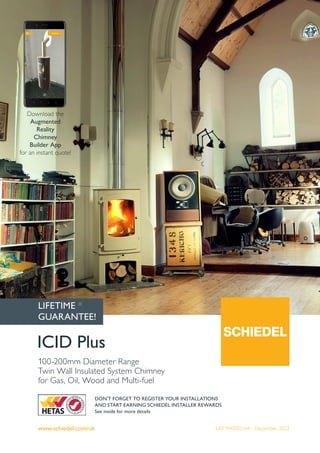
  • 1. SAP 940002164 - December 2022 www.schiedel.com/uk ICID Plus 100-200mm Diameter Range Twin Wall Insulated System Chimney for Gas, Oil, Wood and Multi-fuel DON'T FORGET TO REGISTER YOUR INSTALLATIONS AND START EARNING SCHIEDEL INSTALLER REWARDS See inside for more details LIFETIME * GUARANTEE! Download the Augmented Reality Chimney Builder App for an instant quote!
  • 2. 2 Twist-lock bayonet jointing system. Secured by locking band. Advanced corrosion resistant design and construction uses laser welded 316L stainless steel inner liner and stainless steel case. The 25mm of high density mineral wool insulation maintains flue gas temperature, maximising efficiency, improving flue draught on start up and minimising condensation. Low external case temperature. The inner liner is free to expand through the female collar, allowing for maximum thermal expansion even during a soot fire. The inner liner has an engineered design with an inward bead at the female end which acts as a capillary break preventing moisture being drawn through the joint. Lip seal packs are available containing a quick fit female lip seal with a grease sachet to allow product to be easily adapted for use in Positive Pressure (P) applications for use on condensing positive pressure appliances. Product Description Our ICID range has evolved into a multi-application system adaptable for Dry (D), Fu (W) and even Positive Pressure (P) applications. At Schiedel, we pride ourselves on our technology and innovation and this heating season introduce our evolutionary 3-in-1 system: ICID Plus Ideal not only for traditional stoves but also for pellet stoves, biomass appliances, mini/micro CHP and even condensing boilers capable of withstanding positive pressure. The system is designed so that the outer case is load bearing and the inner liner is free to expand independently, therefore thermal expansion is accommodated within each and every joint of the system. Available in two versions with a choice of either a bright annealed or a matt black painted stainless steel outer case, ICID Plus is available in the following range of diameters:- 100, 125, 150, 180 and 200mm. Front cover image courtesy of Charlotte Smith from St. Mary's Space showing an ICID system installed by Backwoodsman. ICID PLUS PRODUCT FEATURES Joint Design WITHOUT LIP SEAL ICID Plus for N rated Negative Pressure Applications (i.e. Stoves) WITH LIP SEAL ICID Plus for P rated Positive Pressure Applications (i.e. Condensing Boilers) YELLOW PARAFFIN WAX DO NOT SWALLOW YELLO W PA RA FFIN W A X DO N OT SW A LLO W Male Collar Male Spigot Lubricant Female Lip Seal Inward Bead Please note that an updated version of this brochure is always available online https://www.schiedel.com/uk/brochures
  • 3. 3 System Chimney EN1856-1 T450 N1 W V2 L50050 G60 T450 N1 D V3 L50050 G60 60mm Distance to combustibles running through a combustible floor using G60 round firestop T450 N1 W V2 L50050 G50 T450 N1 D V3 L50050 G50 50mm Distance to combustibles a) running through a combustible floor using G50 ventilated fire stops b) In a ventilated shaft using G50 or G60 round ventilated fire stops in combination with G50 ventilated support plate at base and G50 ventilated fire stop plate at top of shaft. c) In free air T200 P1 W V2 L50050 O00 Zero distance to combustibles* Connecting Flue Pipe EN1856-2 T450 N1 D V2 L50050 G100 M Approvals ICID is CE Certified to EN1856-1 TÜV 0036 CPR 9195 010 with designations: ICID is CE Certified to EN1856-2 TÜV 0036 CPR 9195 042 with designations: • Manufactured under a Quality Management Scheme approved to BS EN ISO 9001 • 4 Hour Fire Rating to BS476 Part 20 • Certified for corrosion resistance on gas, oil and solid fuel by Gastec, MPA and TÜV • HETAS listed for use on solid fuel applications. CHIMNEY DIAMETER The chimney size should be as recommended by the appliance manufacturer. Where there is a requirement for a flue diameter smaller than the appliance spigot, then the operational requirements of the appliance and the configuration of the flue must satisfy the flue sizing requirements of EN13384-1 for single appliances, and EN13384-2 for multi appliances. CORROSION RESISTANCE Chimneys are subject to significant corrosion attack by flue gas condensates, particularly from solid fuel. ICID Plus is specifically designed and manufactured to resist this corrosion. Technical Data * For full information refer to p.22 and p.24 ICID (without Lip Seal) ICID Plus (with Lip Seal) Fuel Wood, solid fuel Gas, Oil Firing Temp 450°C 200°C Short Firing Temp 550°C 250°C Thermal Shock 1000°C - Mode of Operation Zero & Negative Pressure Positive Pressure Pressure Capabilities 40Pa 200Pa Fire Rating 4 Hour Fire Rating to BS 476 Part 20 Outer Case (Standard) Stainless Steel Outer Case (Option) Painted matt black Outer Case Thickness 0.5mm Seam Laser or inert gas welded Liner 316L : 1.4404 : X2CrNiMo 17-12-2 Liner Thickness (mm) 0.5mm Seam Laser or inert gas welded Insulation High performance mineral fibre Insulation Thickness 25mm Average Thermal Resistance (200°C) 0.4m2 k/W
  • 4. 4 Typical Installations for Solid Fuel Applications INTERNAL HOUSE Combustible Floors Raincap (without mesh) Angled Flashing Roof Support Ventilated Firestop Plate Ventilated Support Plate Combustible floor Ventilated Firestop Plate Combustible floor Plate SW-DW Stove Pipe Starter Section Prima Smooth Connecting Flue Pipe Combustible shaft Protective wire mesh (required in loft space) INTERNAL HOUSE Non Combustible Floors Taper Terminal Storm Collar Uni-flash Roof Support Firestop Plate Support Plate Non combustible floor Firestop Plate Non combustible floor Adjustable Pipe Anchor Plate Non combustible shaft Protective wire mesh (required in loft space)
  • 5. 5 Typical Installations for Solid Fuel Applications Typical Installations EXTERNAL System Chimney Taper Terminal Structural Wall Band Structural Wall Band Structural Wall Band Extension 45˚ Bend Adjustable Top Plate Cantilever Support 135˚ Tee Mitred Wall Sleeve 45˚ INTERNAL BUNGALOW (VENTILATED LOFT SPACE) Combustible and Non-Combustible floors Raincap (with sparkguard) Angled Flashing Roof Support Prima Smooth Connecting Flue Pipe Protective wire mesh (required in loft space) Round Bungalow Firestop Kit (unventilated) SW-DW Stove Pipe Starter Section TYPICAL CONDENSING BOILER INSTALLATION Tapered Terminal Pipe Wall Band Wall Band 93˚ Tee Wall Support Tee Plug with Drain Ceiling Hanger 93˚ Reducing Tee Appliance Connector Offset Drain Adjustable Pipe Adjustable Pipe TYPICAL BIOMASS INSTALLATION Tapered Terminal 1000mm Pipe Angled Flashing 135˚ Tee Inspection Tee Wall Support Tee Plug with Drain Schiedel Rite-Vent Prima Plus Structural Locking Band Roof Support Wall Band 500mm Pipe 45˚ Elbow Prima Plus to ICID Plus
  • 6. 6 Gasket kits (for use in P rated positive pressure applications) Finish Paint - ICID Plus can be supplied painted in any RAL colour (additional costs apply). The standard finish for ICID Plus is satin. The option of a matt finish is available on request. Dimensions Female Viton Lip Seal Kit Int Ømm 100 125 150 180 200 Ext Ømm 150 180 200 230 250 SAP Code 147322 147323 147324 147325 147326 This female lip seal must be used on wet positive pressure applications and fits into the inward bead on the female socket on the inside of the liner immediately below the male collar. Adjustable Pipe Seal Kit Int Ømm 100 125 150 180 200 Ext Ømm 150 180 200 230 250 SAP Code 152135 152136 152137 152138 152139 This kit consists of a female viton seal which fits into the inward bead on the female socket on the inside of the liner immediately below the male collar and a male viton lip seal which must be fitted into the inward bead of the liner, which is situated in the top half of the 2-piece adjustable pipe, and at the bottom of the liner on the 1-piece adjustable pipe. The dimensions of the flue are: Int Ømm 100 125 150 180 200 Ext Ømm 150 180 200 235 256
  • 7. 7 SW - DW Connector (Open) DN8A047 Int Ømm 125 150 180 200 Ext Ømm 180 200 235 256 This component MUST only be fitted to stove pipe and NOT directly to appliance. SAP Code Plain 125307 126082 126827 127410 SAP Code Black 125308 126079 SW - DW Connector (Closed) DN8A144 Int Ømm 100 125 150 180 200 Ext Ømm 150 180 200 235 256 A 97 123 148 177 198 This component MUST only be fitted to stove pipe and NOT directly to appliance. SAP Code Plain 147329 125287 126060 126810 127393 SAP Code Black 147330 125288 126059 COA COA Uninsulated Increasing Adaptor (SW - DW) DN8A143 Int Ømm 100 125 150 180 200 Ext Ømm 150 180 200 235 256 A - 98 123 148 178 SAP Code Plain - 125320 125321 COA COA SAP Code Black - 144439 125319 COA COA * used on appliances with rear outlet Insulated Appliance Connector Int Ømm 100 125 150 180 200 Ext Ømm 150 180 200 235 256 A 97 123 148 177 198 SAP Code Plain - 146418 146419 146420 146421 SAP Code Black - 146414 146415 146416 146417 Insulated Increasing Adaptor DN8A136 Int Ømm 125 150 180 200 Ext Ømm 180 200 235 256 A 98 123 148 178 B 100 118 116 116 C 50 50 50 50 SAP Code Plain 125305 126077 126824 127408 SAP Code Black 144438 126078 COA COA Starting Components A Int Ø B C A Int Ø 35 30 Int Ø 100 Int Ø A 97 Ext Ø A 77 Insulated Adaptor for Sirius Stove Int Ømm 125 Ext Ømm 180 SAP Code Plain 176051 SAP Code Black 176052 Int Ø 131
  • 8. 8 A Prima Smooth 97 Int Ø A Prima Plus 1037 172 290 Int Ø Ext Ø Int Ø Ext Ø Starting Components Adaptor Prima Smooth to ICID Plus (Dry Applications only) PS027 Int Ømm 125 150 180 200 Ext Ømm 180 200 235 256 SAP Code Plain 109992 110270 126981 127588 SAP Code Black 109991 110268 126980 127587 This component MUST only be fitted to stove pipe and NOT directly to appliance. Double Wall Adjustable Starter Section (1037mm) Int Ømm 100 125 150 180 200 Ext Ømm 150 180 200 235 256 SAP Code Plain - 149644 149645 - 149647 SAP Code Black - 149648 149649 - - Double Wall Adjustable Starter Section (600mm) Int Ømm 100 125 150 180 200 Ext Ømm 150 180 200 235 256 SAP Code Plain - 152214 152215 - 152217 SAP Code Black - 152218 152219 - - Adaptor ICID Plus to Prima Plus DN8A113 Int Ømm 100 125 150 180 200 Ext Ømm 150 180 200 235 256 A 132 132 132 134 134 SAP Code Plain 147331 125292 126062 126813 127396 Adaptor ICID Plus to Prima Smooth (Dry Applications only) Int Ømm 125 150 180 200 Ext Ømm 180 200 235 256 A 132 132 134 134 SAP Code Plain 145516 145517 145518 145519 Black painted Starting Components are finished using high temperature paint | COA : Code on application Adaptor Prima Plus to ICID Plus S027 Int Ømm 125 150 Ext Ømm 180 200 A 130 150 SAP Code Plain 125688 126278 This component MUST only be fitted to stove pipe and NOT directly to appliance. 50 Int Ø A Int Ø Ext Ø Sirius Stove Double Wall Adjustable Starter Section (600mm) Int Ømm 125 Ext Ømm 180 SAP Code Black 175710
  • 9. 9 A Ø 1066 40 42 C Ø A B 72 Flex Ø A B A Ø 352* 100 Starting Components Anchor Plate (Dry Applications only) DN8A0D6 Int Ømm 100 125 150 180 200 Ext Ømm 150 180 200 235 256 A 250 300 320 355 375 B 270 280 300 335 356 C 97 123 148 178 198 Flex Ømm 125 125 155 180 200 SAP Code Plain - 125300* 126072* 126774* 127344* SAP Code Flex 147336 142587 142595 142589 142590 SAP Code Black 147337 142591 142596 142593 142594 SW-DW Adjustable Starter Section (Short) (Dry Applications only) Increasing SW-DW Adjustable Starter Section* (Short) (Dry Applications only) DN8A159 DN8A161 Int Ømm 125 125* 150 180 200 Ext Ømm 180 200 200 235 256 A 123 123 148 178 198 B 352 434 352 352 352 SAP Code Plain 125340 126096 126118 126850 127435 SAP Code Black 125339 131148 126117 126849 127434 This component MUST only be fitted to stove pipe and NOT directly to appliance. SW-DW Adjustable Starter Section (Long) (Dry Applications only) Int Ømm 125 150 Ext Ømm 180 200 A 123 148 B 1066 1066 SAP Code Plain 148503 148504 SAP Code Black 148507 148508 This component MUST only be fitted to stove pipe and NOT directly to appliance. Black painted Starting Components are finished using high temperature paint | COA : Code on application Screwfit adaptor from ICID Plus to TecnoFlex Plus Int Ømm 100 125 150 150 180 200 Flex Ømm 100 125 150 155 180 200 SAP Code Plain 174081 174082 174083 174084 174085 174086 Flex Ømm Nom Ømm 128 A Ø 352 100 UE to ICID Adjustable Starter Section Int Ømm 125 150 Ext Ømm 180 200 A 123 152 B 147 172 SAP Code Plain 175405 175406 SAP Code Black 175408 175409 B Ø
  • 10. 10 Pipes A 40 Eff. Adjustment NOTE: Black product MUST not be connected directly to the stove. Refer to stove starting components 40 A 40 A 40 A 40 A 40 A 1460mm Pipe (1454mm Effective Length) DN8A128 Int Ømm 100 125 150 180 200 Ext Ømm 150 180 200 238 256 A 1454 1454 1454 1454 1454 SAP Code Plain 125253 126019 126780 127350 SAP Code Black 125251 126017 126778 960mm Pipe (954mm Effective Length) DN8A001 Int Ømm 100 125 150 180 200 Ext Ømm 150 180 200 235 256 A 954 954 954 954 954 SAP Code Plain 147343 125285 126058 126808 127392 SAP Code Black 147338 125286 126056 126809 127388 750mm Pipe (744mm Effective Length) DN8A157 Int Ømm 100 125 150 180 200 Ext Ømm 150 180 200 235 256 A 744 744 744 744 744 SAP Code Plain 147347 125273 126045 126797 127380 SAP Code Black 147342 125274 126046 126798 127379 460mm Pipe (454mm Effective Length) DN8A002 Int Ømm 100 125 150 180 200 Ext Ømm 150 180 200 235 256 A 454 454 454 454 454 SAP Code Plain 147344 125269 126039 126793 127376 SAP Code Black 147339 125270 126037 126794 127372 293mm Pipe (287mm Effective Length) DN8A003 Int Ømm 100 125 150 180 200 Ext Ømm 150 180 200 235 256 A 287 287 287 287 287 SAP Code Plain 147345 125261 126030 126786 127362 SAP Code Black 147340 125262 126028 COA 127358 160mm Effective Length DN8A004 Int Ømm 100 125 150 180 200 Ext Ømm 150 180 200 235 256 A 160 160 160 160 160 SAP Code Plain 147346 125258 126025 126784 127357 SAP Code Black 147341 125259 126023 COA COA Adjustable Pipe - 1 Piece 50-230mm DN8A009 Int Ømm 100 125 150 180 200 Ext Ømm 150 180 200 235 256 SAP Code Plain 147351 125298 126071 126819 127402 SAP Code Black 147348 125294 126064 126815 COA This item is converted for use on wet positive pressure applications by using the Lip Seal Kit for adjustable pipes - see page 6 COA : Code on application
  • 11. 11 Ext Ø 108 Ext Ø Int Ø 302 159 Pipes Eff. Adjustment Eff. Adjustment Telescopic Pipe - 2 Piece 215-310mm DN8A151 Int Ømm 100 125 150 180 200 Ext Ømm 150 180 200 235 256 SAP Code Plain 147352 125295 126066 126816 127399 SAP Code Black 147349 144441 126068 COA COA This item is converted for use on wet positive pressure applications by using the Lip Seal Kit for adjustable pipes - see page 6 Telescopic Pipe - 2 Piece 350-570mm DN8A150 Int Ømm 100 125 150 180 200 Ext Ømm 150 180 200 235 256 SAP Code Plain 147353 125297 126069 126818 127401 SAP Code Black 147350 141888 126065 COA 127398 This item is converted for use on wet positive pressure applications by using the Lip Seal Kit for adjustable pipes - see page 6 Locking Band DN8A083 Int Ømm 100 125 150 180 200 Ext Ømm 150 180 200 235 256 SAP Code Plain 147354 125330 126106 126842 127426 SAP Code Black 147355 125331 126107 COA COA Supplied as standard with all components with a female collar Structural Locking Band DN8A092 Int Ømm 100 125 150 180 200 Ext Ømm 150 180 200 235 256 SAP Code Plain 147356 125317 126092 126835 127419 SAP Code Black 147357 125318 126093 COA COA Inspection Pipe with Test Point (Dry and Condensing) Int Ømm 100 125 150 180 200 Ext Ømm 150 180 200 235 256 SAP Code Dry Plain - 148484 148485 148486 148487 SAP Code Dry Black - 148488 148489 - - This component incorporates a locking plug with a spring gasket suitable for high temperature T450 rated dry applications only SAP Code Condensing Plain 152142 148492 148493 148494 148495 This component incorporates a locking plug with a lip seal gasket suitable for low temperature, max T200 rated applications only. ICID Touch Up Paint SAP Code Black 175867 Schiedel have now introduced a black touch up spray paint for use with the standard Black satin RAL 9005 BLDP paint spec, used on ICID Plus. This is available in 400ml spray cans. COA : Code on application
  • 12. 12 Int Ø A C B Int Ø A B C Int Ø A C B 90˚ Tee including Drain Cap (Dry Applications only) DN8A135 Int Ømm 100 125 150 180 200 Ext Ømm 150 180 200 235 256 A 282 301 329 354 394 B 150 154 162 176 195 C 120 133 142 160 170 SAP Code Plain 147360 125282 126054 126805 127387 SAP Code Black 147359 125283 126055 COA COA 93˚ Tee including Drain Cap (Condensing and Dry Applications) Int Ømm 100 125 150 180 200 Ext Ømm 150 180 200 235 256 A 285 297 322 356 396 B 155 158 166 180 201 C 121 136 147 167 177 SAP Code Plain 151975 148110 148112 148114 148117 135˚ Tee including Drain Cap (Condensing and Dry Applications) Int Ømm 100 125 150 180 200 Ext Ømm 150 180 200 235 256 A 325 336 365 414 444 B 254 259 283 326 351 C 254 259 283 326 351 SAP Code Plain 147362 125248 126014 126776 127346 Tees COA : Code on application Int Ø A B C 135˚ Tee including Drain Cap (Dry Applications only) DN8A137 Int Ømm 100 125 150 180 200 Ext Ømm 150 180 200 235 256 A 325 336 365 414 444 B 254 259 283 326 351 C 254 259 283 326 351 SAP Code Plain 147364 125249 126015 126777 127347 SAP Code Black 147365 125250 126016 148190 131796
  • 13. 13 Tees COA : Code on application Tee Plug Int Ømm 100 125 150 180 200 Ext Ømm 150 180 200 235 256 SAP Code Plain COA 125343 126121 126853 127438 SAP Code Black COA COA 126122 COA COA Draught Stabiliser Int Ømm 100 125 150 180 200 Ext Ømm 150 180 200 235 256 SAP Code Plain - 138143 138145 149525 138147 SAP Code Black - COA COA COA COA Draught Stabiliser with Explosion Relief Int Ømm 100 125 150 180 200 Ext Ømm 150 180 200 235 256 SAP Code Plain - 149521 138148 138144 149526 SAP Code Black - COA COA COA COA 135˚ Long Tee including Drain Cap - Adjustable (Dry Applications only) Int Ømm 125 150 Ext Ømm 180 200 A 336 365 B 259 283 C Min/Max 815/1193 841/1219 D Min/Max 576/844 844/862 SAP Code Plain 154662 154663 SAP Code Black 154664 154665 C A Ext B D
  • 14. 14 Bends A B COA : Code on application A B A A B 15˚ Bend DN8A018 Int Ømm 100 125 150 180 200 Ext Ømm 150 180 200 235 256 A 60 63 63 63 64 B 56 55 56 56 57 SAP Code Plain 147372 125256 126022 126782 127353 SAP Code Black 147368 125254 126020 COA COA 30˚ Bend DN8A019 Int Ømm 100 125 150 180 200 Ext Ømm 150 180 200 235 256 A 63 66 70 73 77 B 59 57 61 64 68 SAP Code Plain 147373 125264 126033 126788 127366 SAP Code Black 147369 144442 126031 COA COA 45˚ Bend DN8A017 Int Ømm 100 125 150 180 200 Ext Ømm 150 180 200 235 256 A 76 79 83 91 95 B 74 70 74 82 86 SAP Code Plain 147374 125267 126036 126791 127371 SAP Code Black 147370 125265 126034 126789 127367 Structural Locking Band for Bends DN8A155 Int Ømm 100 125 150 180 200 Ext Ømm 150 180 200 235 256 A 56 56 56 56 56 SAP Code Plain 147376 125342 126120 126852 127437 SAP Code Black 147377 125341 126119 126851 127436
  • 15. 15 Bends COA : Code on application A B A B A B Typical Offsets (made by assembling 2 bends) A B A B 15˚ Offset Int Ømm 100 125 150 180 200 Ext Ømm 150 180 200 238 256 A 228 232 234 234 238 B 30 31 31 31 31 30˚ Offset Int Ømm 100 125 150 180 200 Ext Ømm 150 180 200 238 256 A 228 230 244 256 271 B 61 62 65 69 73 45˚ Offset Int Ømm 100 125 150 180 200 Ext Ømm 150 180 200 238 256 A 256 254 268 295 309 B 106 105 111 122 128 90˚ Bend DN8A015 Int Ømm 100 125 150 180 200 Ext Ømm 150 180 200 235 256 A 131 146 156 174 184 B 122 137 147 165 175 SAP Code Plain 147375 125277 126049 126800 127382 SAP Code Black 147371 125275 126047 COA COA 87˚ Bend Int Ømm 100 125 150 180 200 Ext Ømm 150 180 200 235 256 A 125 141 151 196 179 B 122 138 147 164 175 SAP Code Plain 151971 148023 148024 148025 148026
  • 16. 16 B A E f f e c t i v e P i p e B E f fe c t iv e P ip e A Typical Offsets (made by assembling 2 bends and a standard pipe section) B A E f f e c t i v e P i p e 15˚ Bend offset with Standard Pipe Length Int Ømm 100 125 150 180 200 Ext Ømm 150 180 200 238 256 1454 Effective Pipe A 1633 1636 1638 1638 1642 B 406 407 407 407 408 954 Effective Pipe A 1150 1153 1155 1155 1159 B 277 277 278 278 278 744 Effective Pipe A 947 951 953 953 957 B 223 223 223 223 224 454 Effective Pipe A 667 671 672 672 676 B 148 148 148 148 149 287 Effective Pipe A 505 509 511 511 515 B 104 105 105 105 106 160 Effective Pipe A 383 387 388 388 392 B 71 72 72 72 73 30˚ Bend offset with Standard Pipe Length Int Ømm 100 125 150 180 200 Ext Ømm 150 180 200 238 256 1454 Effective Pipe A 1487 1489 1504 1515 1530 B 788 789 793 796 800 954 Effective Pipe A 1054 1056 1071 1082 1097 B 538 539 543 546 550 744 Effective Pipe A 872 874 889 900 915 B 433 434 438 441 445 454 Effective Pipe A 621 623 638 649 664 B 288 289 293 296 300 287 Effective Pipe A 476 478 493 504 519 B 205 205 209 212 216 160 Effective Pipe A 366 368 383 394 409 B 141 142 146 149 153 45˚ Bend offset with Standard Pipe Length Int Ømm 100 125 150 180 200 Ext Ømm 150 180 200 238 256 1454 Effective Pipe A 1284 1282 1296 1323 1337 B 1134 1133 1139 1150 1156 954 Effective Pipe A 931 929 943 970 984 B 781 780 786 797 803 744 Effective Pipe A 782 780 794 821 835 B 632 631 637 648 654 454 Effective Pipe A 577 576 590 616 630 B 427 427 433 443 449 287 Effective Pipe A 459 457 471 498 512 B 309 308 314 325 331 160 Effective Pipe A 369 367 381 408 422 B 219 218 224 235 241 COA : Code on application
  • 17. 17 B A A Typical Offsets (made by assembling 2 bends and a standard pipe section) Offsets for 135˚ Tee and 45˚ Bend Int Ømm 100 125 150 180 200 Ext Ømm 150 180 200 238 256 A 383 402 435 497 532 B 303 310 334 376 402 Offsets for 135˚ Tee and 45˚ Bend Int Ømm 100 125 150 180 200 Ext Ømm 150 180 200 238 256 A 232 233 252 288 309 G50 Firestop Components Combustible Floor G50 Round Ventilated Firestop Plate 1 Piece Int Ømm 125 150 Ext Ømm 180 200 A 183 241 B 380 400 SAP Code Plain 175701 175702 SAP Code Black 175703 175704 Combustible Floor G50 Square Ventilated Support Plate 1 Piece Int Ømm 125 150 Ext Ømm 180 200 A 183 241 B 380 400 SAP Code Plain 175707 175708 Combustible Floor G50 Square Ventilated Firestop Plate 1 Piece Int Ømm 125 150 Ext Ømm 180 200 A 183 241 B 380 400 SAP Code Plain 175705 175706 B A B A B A Magnetic Firestop Cover Plate Kit 9509 Int Ømm 100 125 150 180 200 Ext Ømm 150 180 200 235 256 A 154 183 203 241 259 B 370 380 400 430 450 SAP Code Plain 147378 126945 127552 128127 128611 SAP Code Black 147379 126946 127553 128128 128612 SAP Code White 147380 126947 127554 128129 128613 B A
  • 18. 18 Combustible Floor Round Ventilated Firestop Plate - 1 Piece* Round Ventilated Firestop Plate - 2 Piece 9423 9424 Int Ømm 100 125 150 180 200 Ext Ømm 150 180 200 235 256 A 153 183 203 241 259 B 350 380 400 430 450 SAP Code 1PC Plain 125902 126661 127227 128117 128601 SAP Code 1PC Black 125900 126659 127225 128115 128599 SAP Code 1PC White 125901 126660 127226 128116 128600 SAP Code 2PC Plain 125905 126664 127230 128120 128604 SAP Code 2PC Black 125903 126662 127228 128118 128602 SAP Code 2PC White 125904 126663 127229 128119 128603 G60 Firestop Components Bungalow Firestop Kits B A All Unventilated Bungalow Firestop Kits may only be used on a combustible ceiling in a bungalow where there is a minimum 50mm distance to combustibles where the chimney penetrates the ceiling area and where the roof space above the ceiling is open and ventilated. Within the roof space, a protective wire mesh framework must be built around the chimney to ensure the minimum 50mm distance to combustibles is maintained. B A Unventilated Bungalow Round Firestop Plate - 1 Piece and 2 Piece 9428 9429 Int Ømm 100 125 150 180 200 Ext Ømm 150 180 200 235 256 A 153 183 203 241 259 B 350 380 400 430 450 SAP Code Plain 1 PC 147381 126526 127108 128084 128571 SAP Code Black 1 PC 147382 126528 127110 128086 128572 SAP Code White 1 PC 147383 126529 127111 - - SAP Code Plain 2 PC 147384 126527 127109 - - SAP Code Black 2 PC 147385 131122 127106 - - SAP Code White 2 PC 147386 - 127107 - - COA : Code on application B C A B C A Combustible Floor G60 Ventilated Support Plate - 2 Piece Combustible Floor G60 Rectangular Ventilated Firestop Plate - 2 Piece 95260 94250 Int Ømm 100 125 150 180 200 Ext Ømm 150 180 200 235 256 A 153 183 203 241 259 B 350 380 400 430 450 C 175 190 200 215 225 SAP Code Support Plate 125908 126667 127234 128124 128607 SAP Code Firestop Plate 125907 126666 127232 128122 128606 B B A A
  • 19. 19 Wall Support Side Plates DN8A0D2 Int Ømm 100 125 150 180 200 Ext Ømm 150 180 200 235 256 A 235 275 295 325 345 B 165 160 180 210 230 C 470 470 470 470 470 D 100 100 100 100 100 SAP Code Plain 101043 125357 126136 126862 127445 SAP Code Black - 125355 126133 - - B D C E Cantilever Support Type 325 - 95420001 Type 475 - 95420002 Type 325 475 Int Ømm Range 00-150 100-200 A 325 475 B 242 242 SAP Code Plain 101742 101743 SAP Code Black 130686 130687 Used in combination with Adjustable Top Plate. B A Support Components Top Plate DN8A0D3 Int Ømm 100 125 150 180 200 Ext Ømm 150 180 200 235 256 A 266 276 296 334 352 B 247 287 307 342 363 C 127 142 152 170 180 D 106 106 106 105 108 SAP Code Plain 147387 125140 125833 126572 127151 SAP Code Black 147388 125141 125834 COA COA B C D A Cantilever Support Type 570 - 95420003 Type 570 Int Ømm Range 100-200 A 570 B 330 SAP Code Plain 101744 SAP Code Black 130688 Used in combination with Adjustable Top Plate. B A Retrofit Wall Supports Int Ømm 100 125 150 Ext Ømm 150 180 200 SAP Code Plain 60mm - 200mm 169699 169700 169701 SAP Code Black 60mm - 200mm 169696 169697 169698 SAP Code Plain 200 - 375mm 170321 170322 170323 SAP Code Black 200 - 375mm 170318 170319 170320 NEW!
  • 20. 20 B A A B A C Type W1 Types L1, L2 60 B A A Support Components Wall Band (60mm) 92930 Int Ømm 100 125 150 180 200 Ext Ømm 150 180 200 235 256 A 148 180 200 238 256 B 135 140 150 168 178 SAP Code Plain 125898 126648 127213 128110 128594 SAP Code Black 131170 126620 127196 128095 128580 Adjustable Back Bracket for Wall Band 60-300mm 95950 Int Ømm 100 125 150 180 200 Ext Ømm 150 180 200 235 256 A 83 112 132 162 186 SAP Code Plain 125890 126623 127199 128098 128583 SAP Code Black - 126622 127198 128097 128582 Structural Wall Band (50mm) 95430 Int Ømm 100 125 150 180 200 Ext Ømm 150 180 200 235 256 A 126 144 164 194 214 B 55 55 55 55 55 SAP Code Plain 101264 101265 101266 128112 128596 SAP Code Black - 126654 127218 - - Structural and Retrofit Wall Band Extensions W1 - 95440001 L1 - 95440004 L2 - 95440005 Type W1 L1 L2 Adj. 55-100 100-250 100-440 A 130 300 450 B 36 - - C - 32 32 SAP Code Plain 101735 143846 143847 SAP Code Black 130824 144655 144656 COA : Code on application Retrofit Wall Band 95600 Int Ømm 100 125 150 180 200 Ext Ømm 150 180 200 235 256 A 136 151 161 180 189 B 300 330 350 388 406 SAP Code Plain 147389 126657 127223 128113 128597 SAP Code Black 147390 126658 127224 128114 128598 60 60 B A COA : Code on application
  • 21. 21 A 330 330 Support Components Ceiling Joist Support/Ventilated Support Plate Int Ømm 100 125 150 180 200 Ext Ømm 150 180 200 238 256 A 291 321 341 379 397 SAP Code Plain G60 Ceiling Joist Support 125908 126667 127234 128124 128607 Plain G50 Ceiling Joist Support - 175707 175708 - - Roof Support 94640 Int Ømm 100 125 150 180 200 Ext Ømm 150 180 200 235 256 SAP Code Plain 100961 100962 100963 128126 128610 Guy Wire Bracket 95900 Int Ømm 100 125 150 180 200 Ext Ømm 150 180 200 235 256 SAP Code Plain 100640 100641 100642 128101 128586 SAP Code Black - 131808 127202 - - Wall Sleeve 90˚ Masonry - 94980 Timber Frame - 94810 Int Ømm 100 125 150 180 200 Ext Ømm 150 180 200 235 256 A Masonry 200 230 250 288 306 A Timber F 270 300 320 358 376 SAP Code Masonry 147392 126642 127206 - - SAP Code Timber 125897 126647 127212 128108 128592 B A Ceiling Joist Support Arms (Pair) 9459001 Type 570 Int Ømm Range 125-200 A 39 B 700 SAP Code Plain 130694 Used in combination with Ceiling Joist Support. COA : Code on application Telescopic Roof Stays Ext Ømm 150 180 200 235 256 SAP Code Black 170141 170142 170143 170145 170147 B A
  • 22. 22 B A B D A C B A B D A C Support Components COA : Code on application 1 Piece Trim Collar 90˚ 9580 Int Ømm 100 125 150 180 200 Ext Ømm 150 180 200 235 256 A 154 184 204 242 260 B 300 330 350 388 406 SAP Code Plain - 127038 127642 128133 128618 SAP Code Black 126337 127039 127643 128134 128619 2 Piece Trim Collar 90˚ 9599 Int Ømm 100 125 150 180 200 Ext Ømm 150 180 200 235 256 A 154 184 204 242 260 B 300 330 350 388 406 SAP Code Plain 126338 127040 127644 - -- SAP Code Black 126339 127041 127645 - COA 1 Piece Trim Collar 45˚ 9589 Int Ømm 100 125 150 180 200 Ext Ømm 150 180 200 235 256 A 154 184 204 242 260 B 216 259 287 341 366 C 300 330 350 388 406 D 412 454 483 536 562 SAP Code Plain 147393 126612 127186 128089 128575 SAP Code Black 147394 126613 127187 128090 128576 SAP Code White 147395 126614 127188 128091 128577 2 Piece Trim Collar 45˚ 9579 Int Ømm 100 125 150 180 200 Ext Ømm 150 180 200 235 256 A 154 184 204 242 260 B 108 130 144 171 183 C 300 330 350 388 406 D 206 227 242 268 281 SAP Code Plain 126335 127035 127639 128130 128615 SAP Code Black 126336 127036 127640 128131 128616 SAP Code White - 127037 127641 128132 128617 A Wall Sleeve 45˚ Masonry - 94620 Timber Frame - 94910 Int Ømm 100 125 150 180 200 Ext Ømm 150 180 200 235 256 A Masonry 200 230 250 288 306 A Timber F 270 300 320 358 376 SAP Code Masonry 125894 126641 127205 128102 128587 SAP Code Timber 125895 126643 127207 128103 128588 Supplied as a 1m long mitred tube to be cut to length on site
  • 23. 23 B C 90 A B C 90 A B C 90 A Loft Guard 1000 Ø A Support Components COA : Code on application Adjustable Trim Collar 35-45˚ Int Ømm 100 125 150 180 200 Ext Ømm 150 180 200 235 256 A - 187 204 242 260 B - 364 384 422 440 C - 204.5 214.5 238.5 247.5 SAP Code Plain - 126513 127093 128071 128558 SAP Code Black - 126511 127091 128069 128556 SAP Code White - 126512 127092 128070 128557 Adjustable Trim Collar 0-20˚ Int Ømm 100 125 150 180 200 Ext Ømm 150 180 200 235 256 A - 187 204 242 260 B - 364 384 422 440 C - 204.5 214.5 238.5 247.5 SAP Code Plain - 126507 127087 128065 128552 SAP Code Black - 126505 127085 128063 128550 SAP Code White - 126506 127086 128064 126512 Adjustable Trim Collar 20-35˚ Int Ømm 100 125 150 180 200 Ext Ømm 150 180 200 235 256 A - 187 204 242 260 B - 364 384 422 440 C - 204.5 214.5 238.5 247.5 SAP Code Plain - 126510 127090 128068 128555 SAP Code Black - 126508 127088 128066 128553 SAP Code White - 128067 127089 128067 128554 Loft Guard Int Ømm 100 125 150 180 200 Ext Ømm 150 180 200 235 256 Ø A - 300 320 350 376 SAP Code Plain - 137464 137464 137465 137465 Loft Guard - for Scottish Regulations Int Ømm 180 200 Ø A 300 320 Ø B 400 420 SAP Code Plain 158404 158405 560 A B
  • 24. 24 Ignis-Protect In order to meet the latest European building regulations, specific leakage and performance criteria have to be met, which are much more stringent than in the past. These criteria are key in relation to chimney products passing through combustible walls. Schiedel Chimney Systems have invested heavily to provide tested and approved solutions to resolve these challenges and are proud to introduce their latest cutting edge product. Product Description IGNIS-PROTECT, Winner of Best Product Award Hearth & Home Exhibition 2015. • Z-7.4-3372 relating to T450 designated products • Z-7.4-3402 relating to T600 designated products Approvals DIBt Zulassungs Nr. Z-7.4-3372 Deutsches Institut für Batechnik PRODUCT FEATURES Suitable for SW and DW connecting flue pipes passing through interior or exterior walls made of combustible materials Available in two versions: • For exterior walls (with aluminium laminate on inside face) • For interior walls (without aluminium laminate and with an extended removable core) Available in both 90° and 45° versions For flue gas temperature up to: • 450 °C for SW connecting flue pipes (T450) • 600 °C for DW connecting flue pipes(T600) IGNIS-PROTECT Internal Wall Block (with freely moving outer protection pipe) INTERNAL EXTERNAL Flue pipe side 24mm projection Chimney side 50mm projection 350 x 350mm IGNIS-PROTECT External Wall Block (with fixed outer protection pipe) 350 x 350mm INTERNAL EXTERNAL Flush with outside Inside 24mm projection Protected in accordance with European patent specification EP 1 878 849 B1 Designed specifically for Air Tight, Energy Efficient and Timber Framed Buildings Max. 100 °C surface temperature during soot fire Monolithic component made of mineral wool, density 120 kg/m³, building material class A1 Internal face finished with aluminium laminate External face made with textured surface to facilitate facade rendering Removable pipe sections DN 125, 130, 150, 180, 200 mm IGNIS-PROTECT can be used without any additional protec- tion Available in a range of standard wall thicknesses between 100mm -500mm
  • 25. 25 Ignis-Protect (for air tight wall penetration) For more information on IGNIS-PROTECT 90˚ and 45˚ please refer to p.30 SAP Code Thickness (mm) Height (mm) Width (mm) Pallet Quantity Ignis-Protect 90˚ Version 101841 101842 101843 101844 101845 101846 150 200 250 300 350 400 700 700 700 700 700 700 565 565 565 565 565 565 12 9 6 4 4 2 Ignis-Protect 45˚ Version 149530 149531 149532 149533 149534 149535 149536 100 150 200 250 300 350 400 1020 1020 1020 1320 1320 1320 1320 565 565 565 565 565 565 565 18 12 9 6 4 4 2 Prima Smooth Stove Pipe Plasterboard Permanently elastic sealing strip Timber framework for Ignis-Protect Ignis Protect - 45° External version Vapour barrier membrane Schiedel Isokern Double Module System Insulation Damp proof barrier Hearth IGNIS-PROTECT 45˚ VERSION IGNIS-PROTECT ICID PLUS ON TRADITIONAL TIMBER FRAME WALL Appliance 60 1020 620 183 Min 600 Heat proof board ICID Plus flue pipe Timber frame Ignis-Protect Suitable cavity wall sleeve Trim collar Trim collar
  • 26. 26 PRODUCT FEATURES Ø455 550 48 600 x 600 (EPDM) 700 200 48 Ø255 Support bracket Plasterboard Vapour barrier Protect Box Insulation Wooden substructure for plasterboard EPDM seal EPDM is fixed to the vapour barrier with tape and screw to the wooden structure Engineered to meet the key challenges of modern houses... Schiedel Protect Box is the proven solution to safeguard distance to combustible materials in low energy and passive houses. • Ever more air tight construction • Increasing depth of loft insulation Designed to meet blower door test. Constructed using a high temperature resistant Rockwool insulation with an aluminium laminate outer surface to give zero distance to combustibles. An EPDM kit is available to allow for the chimney to pass through an air tight membrane at ceiling level in a cold roof construction or at roof level in a warm roof construction. Standard height 700 mm to meet new roof insulation re- quirements. Protect Box Protect Box SAP Code 121342 EPDM Seal SAP Code 136939
  • 27. 27 Protect Box and Accessories (for air tight ceiling/roof penetration) Ø A Int Ø Ø C D COA : Code on application A4 5 A A A C 295 Protect Box Int Ømm 251 Ext Ømm 451 SAP Code 121342 EPDM Seal SAP Code 136939 Bends Int Ømm 150 Ext Ømm 250 SAP Code 45o Bend 104804 Anti Downdraught Term. With Mesh Int Ømm 150 Ext Ømm 250 SAP Code 115244 Tapered Terminal Int Ømm 150 Ext Ømm 250 SAP Code 114311 Uniflash Int Ømm 150-300 A 685 SAP Code 112197 Roof Support Int Ømm 150 Ext Ømm 250 SAP Code 100965 Storm Collar Int Ømm 150 Ext Ømm 250 SAP Code 106143 Pipes Int Ømm 150 Ext Ømm 250 SAP Code 1000 mm 104784 SAP Code 500 mm 104779 SAP Code 250 mm 104774 Raincaps Int Ømm 150 Ext Ømm 250 SAP Code No Mesh 126241 SAP Code With Mesh 126240 ICID Plus - ICS50 Adaptor Int Ømm 125 150 Ø A 180 200 Ø B 150 150 Ø C 251 250 D 195 195 SAP Code Plain 171864 148919 SAP Code Black 171863 148920 Ø B
  • 28. 28 Typical Installations PROTECT BOX IN SITU SCHIEDEL PROTECT BOX THROUGH PITCHED ROOF Protect Box Kit EPDM Seal (around ICS50) ICID Plus Pipe Length ICS50 Pipe Length Roof Insulation (max 600mm height) Ceiling Vapour Barrier ICID Plus - ICS50 Adaptor Solid Firestop Air Tight Membrane Trim Collar ICID / ICS 25 ICID / ICS 25 - ICS 50 Schiedel PROTECT BOX EPDM Seal ICS 50 Storm Collar Flashing Roof Tiles Sealant Strip Air Tight Membrane EPDM Seal Air Tight Membrane
  • 29. 29 Flashings A A 150 150 A A 50 A A COA : Code on application Angled Flashing Kit 5˚- 45˚ 95510 Int Ømm 100 125 150 180 200 Ext Ømm 150 180 200 235 256 A 610 610 700 700 800 SAP Code Plain 125889 126621 127197 128088 128574 SAP Code Black - - 130662 - - Flat Flashing Kit 95530 Int Ømm 100 125 150 180 200 Ext Ømm 150 180 200 235 256 A 610 610 610 610 610 SAP Code Plain 125892 126625 127201 128100 128585 SAP Code Black - - 131807 - - Storm Collar Int Ømm 100 125 150 180 200 Ext Ømm 150 180 200 235 256 SAP Code Plain 106138 106140 106141 128106 128590 SAP Code Black - 126645 127209 128105 - Uniflash Product Code 94540001 94540002 Ext Ømm 80-200 150-300 A 500 685 SAP Code 112198 112197 Universal EPDM rubber/aluminium flashing. Just pull the required diameter tab on the rubber seal.
  • 30. 30 Terminals A B A B A B A B A Int Ø Raincap with 10mm sparkguard DN8A145 Int Ømm 125 150 Ext Ømm 180 200 A 266 310 B 90 90 SAP Code Plain 125336 126112 SAP Code Black 133925 Raincap with 25mm anti-bird mesh DN8A140 Int Ømm 100 125 150 180 200 Ext Ømm 150 180 200 235 256 A 266 266 310 362 362 B 70 90 90 90 115 SAP Code Plain 147399 125337 133921 126847 127431 SAP Code Black 147400 125335 133924 126845 127432 Raincap without mesh DN8A142 Int Ømm 100 125 150 180 200 Ext Ømm 150 180 200 235 256 A 266 266 310 362 362 B 70 90 90 90 115 SAP Code Plain 147401 125144 133923 126574 127153 SAP Code Black 147402 125145 133926 126575 - Insulated Tapered Terminal DN8A038 Int Ømm 100 125 150 180 200 Ext Ømm 150 180 200 235 256 A 204 200 200 204 240 SAP Code Plain 147403 125351 126130 126857 127441 SAP Code Black 147404 125352 126129 126858 - Anti-splash Anti-downdraught Terminal (Gastec Approved) Int Ømm 100 125 150 180 200 Ext Ømm 150 180 200 230 250 A - 142 170 204 204 B - 254 304 354 404 SAP Code with mesh Plain - 125302 126074 126821 127406 SAP Code with mesh Black - - - - - SAP Code without mesh Plain - 125303 126075 126822 127406 SAP Code without mesh Black - 125301 126073 - 131797 COA : Code on application
  • 31. 31 Distance to Combustibles on high temperature (T450) applications (see p.17) INTERNAL HOUSE Combustible Floors Fig. 1 Fig. 2 50mm 50mm 50mm INTERNAL BUNGALOW (VENTILATED LOFT SPACE) Combustible and Non-Combustible Floors 60mm 60mm Ventilated G50 Fire Stop and G50 Support Plate Combination Ventilated G60 Fire stop and G60 Support Plate combination
  • 32. 32 OUTLET SITING FOR SOLID FUEL APPLIANCES (<50KW) Point where flue passes through weather surface (Notes 1, 2) Clearance to flue outlet A At or within 600mm of the ridge At or within 600mm above the ridge B Elsewhere on the roof (whether pitched or flat) At least 2300mm horizontally from the nearest point on the weather surface and:a) at least 1000mm above the highest point of intersection of the chimney and the weather surface; or b) at least as high as the ridge C Below (on a pitched roof) or within 2300mm horizontally to an openable roof-light, dormer window or other opening (Note 3) At least 1000mm above the top of the opening D Within 2300mm of an adjoining or adjacent building, whether or not beyond the boundary (Note 3) At least 600mm above any part of the adjacent building within 2300mm System Design LOCATION OF OUTLET OUTLET SITING Flue terminations for solid fuel & oil are subject to EN15287-1 2007. Figures A and B illustrate recommendations for the most commonly encountered outlet terminations. Flue terminations for gas in domestic situations are governed by the BS5440-1 2008 Section 4.2. Figure C illustrates recommendations for the most common siting situations encountered. Adjacent taller structures may require increased height. The minimum flue projection through the roof is 600mm to the underside of the terminal. FLUE ROUTING The chimney should remain as straight as possible through its vertical run to assist flow. Should it be necessary to offset a chimney run the following guidelines should be adhered to: It is recommended that a vertical rise of 600mm should be allowed immediately above the appliance before any change of direction. Within a system, on all fuels, there should be no more than 4 changes of direction of maximum 45°. 90° Factory made bends or tees within the system may be treated as being equal to two 45° bends (see Document J of the Building Regulations issued October 1st 2010). TERMINAL TYPES On solid fuel appliances, an open termination is normally recommended. However in certain conditions, rain caps or anti- downdraught terminals may be used. Rain caps and anti-downdraught terminals are available in two versions, with mesh/spark guard and without mesh. Where a terminal with mesh is used, there is a risk of soot build up, and therefore regular cleaning is required to avoid blockage, particularly when using oil or solid fuel. PROVISION FOR SWEEPING, CLEANING AND MAINTENANCE Provision should be made for inspecting and cleaning the chimney. To aid cleaning, sufficient distance should be left between changes of direction to permit the safe passage of cleaning brushes within the system. This is particularly important on solid fuel applications. It is recommended that chimneys serving solid fuel appliances be swept as frequently as necessary but at least twice a year. Choose an access component suitable for your installation unless cleaning/inspection can be done through the appliance. P O N M A D B C A 600mm min 600mm min less than 600mm 1500 1500 P O N M A D B C A 600mm min 600mm min less than 600mm 1500 1500 600 min Chimney should not penetrate within the shaded area 600 600 2000 Fig. A Outlet siting for Oil Appliances (<45kW) Fig. B Outlet siting for Solid Fuel Appliances (<50kW) OUTLET SITING FOR OIL APPLIANCES (<45KW) Location of outlet Pressure Jet Burner Vapourising Burner M Above the highest point of an intersection with the roof 600mm 1000mm N From a structure to the side of the terminal 750mm 2300mm O Above a vertical structure which is less than 750mm (pressure jet burner) or 2300mm (vapourising burner) horizontally from the side of the terminal 600mm 1000mm P From a ridge terminal to a vertical structure on the roof 1500mm Should not be used
  • 33. 33 System Design ROOM VENTILATION The room carrying the appliance should have an air vent either direct to an external air source or vented into a room that has an external vent direct to an air source. This is required to provide adequate air supply to allow the appliance and flue to operate efficiently. These requirements are specified in the Building Regulations (Document J) also by CIBSE and BS5440. COMMERCIAL INSTALLATIONS Schiedel Rite-Vent can provide a full design & flue sizing advice service for commercial installations, using both ICID Plus and our ICS product ranges. PROVISION FOR CONDENSATE DISPOSAL (subject to appliance manufacturer recommendations) Normally solid fuel and atmospheric gas and oil appliances will not need a drain unless rain ingress is significant. Most condensing appliances however need provision for drainage. As a rule of thumb a condensing boiler produces 1 to 1.5 litres of condensate per hour per 10kW of input. This is a significant amount of acidic liquid which must be drained from the system. Choose appropriate flue drainage components, normally fitted at the base of the stack and close to the appliance outlet. On high efficiency or on condensing systems, a 3° slope on horizontal runs is advised, using the appropriate 87° bend and 93° tee. A D B C A 600mm min 600mm min less than 600mm 1500 1500 600 min Chimney should not penetrate within the shaded area 600 600 2000 A B C 600mm min less than 600mm 1500 1500 600 min Chimney should not penetrate within the shaded area 600 600 2000 Fig. C BS 5440-1Outlet siting for Gas Appliances (<70kW) 1. The weather surface is the building external surface, such as its roof, tiles or external walls. 2.A flat roof has a pitch less than 10˚. 3. The clearance for A or B, as appropriate, will also apply. 4. A vertical flue fixed to an outside wall should be treated as equivalent to an inside flue emerging at the nearest edge of the roof. Diagram A Diagram B Load Bearing Data Maximum Load Bearing (metres of pipe) Internal Diameter (mm) 80-130 150-180 200-250 Base Drain Section 22 18 18 Retrofit Wall Support 10 10* - Drain Plug Support 18 18 18 Adjustable Top Plate + Locking Band 15 15 15 Telescopic Floor Support 18 18 18 Pair of Side Plates (see diagram A) 15 15 15 Pair of Side Plates (see diagram B) 10 10 10 Cantilever Support 22 18 18 Extension Support (Anchor Plate) 1.5 1.5 1.5 Ventilated Support Plate (All types) 12 12 9 Support Plate 12 12 9 Ceiling Hanger 1.5 1.5 1.5 Wall Band 50/60mm 3 3 3 Adjustable Wall Band 60-300mm 3 3 3 Structural Wall Band 4 4 4 Extension for Structural Wall Band 4 4 4 Guy Wire Bracket 1.5 1.5 1.5 Roof Support (above truss) 6 6 6 Roof Support (below truss) 4 4 4 90° Tee + Locking Band 22 18 18 93° Tee + Locking Band 22 18 18 135° Tee + Locking Band 15 10 10 Inspection Tee (Round) 22 18 18 Inspection Tee (Rectangular) 22 18 18 Approximate Weights of Products (Kg) Internal Diameter Length(mm) 1000 500 250 195 80 4.32 2.13 1.09 0.85 100 5.14 2.53 1.29 1.01 130 6.35 3.14 1.60 1.24 150 7.18 3.54 1.86 1.41 180 8.40 4.14 2.11 1.65 200 9.22 4.55 2.31 1.80 230 10.44 5.13 2.62 2.03 250 11.24 5.53 2.81 2.19 300 15.08 7.58 3.44 2.47 * Retrofit Wall Support available diameters 80 - 150 only
  • 34. 34 Installation These notes should be read in conjunction with the detailed ICID Plus Installation Instructions. MANDATORY REQUIREMENTS Connection to an appliance that is connected to the fuel supply must be carried out by a GAS SAFE (gas) or OFTEC (oil) registered installer. We recommend the use of HETAS approved installers for solid fuel applications. For full design and installation details the key referral documents are: • BS EN 1856-1: Chimneys - System Chimney Products • BS EN 1859: Metal Chimneys - Testing Methods • BS EN 1443: Chimneys - General Requirements • BS EN 15287-1: Chimneys. Design, installation and commissioning of chimneys. Chimneys for non-room sealed heating appliances. • BS 5440-1: Flueing and ventilation for gas appliances of rated input not exceeding 70kW net (1st, 2nd and 3rd family gases) • Specification for installation of gas appliances to chimneys and for maintenance of chimneys. • Approved Document J: - Combustion appliances and fuel storage systems (England & Wales) • DFP Technical Booklet L: - Combustion appliances and fuel storage systems (NI) • Technical Handbook (Domestic & Non Domestic), Section 3 - Environment (Scotland) • Appliance Installation Instructions and related standards. Other standards covering specific applications will also be relevant and must be adhered to. • Planning permission may be required, and reference should be made to the local Building Control Department. ENCLOSURE/SHAFTS With the exception of the room containing the appliance, where the chimney passes through any part of the building, where there is a risk of accidental human contact, i.e a bedroom etc., or where there is a risk of contact with combustible materials stored in a cupboard or in the roof-space, the chimney must be enclosed in an appropriate way to meet Building Regulations. This can be achieved by boxing in the chimney in habitable rooms, or by the use of a protective wire mesh frame in roof spaces etc. In all cases the minimum distance to any combustible material, including loft insulation, must be respected according to the table on p.3, and any enclosure should be ventilated using the appropriate ventilated fire stops (see p.17). DISTANCE TO COMBUSTIBLES In accordance with building regulations its is essential that the correct distance to combustible material is maintained. On solid fuel applications, where there is a risk of soot fire, a distance of 60mm to combustibles must be maintained within a combustible floor and within a combustible shaft, where the old G60 ventilated fire stop plates and G60 ventilated support plate are used (see Fig.1 p.31). Where the new G50 ventilated firestop plates and G50 ventilated support plates are used, then this distance to combustibles is reduced to 50mm both within the floor space and within the shaft. There is no need to line the area within the floor cavity with plasterboard; however the ventilated fire stop plate and ventilated support plate must be used. On gas and oil applications, a distance of 50mm to combustibles must be maintained within a combustible floor and within a combustible shaft. The ventilated fire stop plate and ventilated support plate must be used. Where the chimney penetrates a non combustible floor and where a non combustible shaft is used, a distance of 50mm to the shaft is sufficient. In this case, non ventilated fire stops and non ventilated support plates may be used at first floor level with a ventilated fire stop being used where the chimney penetrates into the roof space. On bungalow applications where the chimney runs through either a combustible or non-combustible ceiling, an unventilated bungalow fire stop plate kit can be used. Please note that an unventilated support plate can not be used above the ceiling in this case. The weight of the chimney should be supported using the roof support (see p.21). Distance to combustibles must be respected within the ceiling space (see Fig. 2 p.31) and mesh frame should be used within the loft space, which must be ventilated (see Fig. 2 p.31). JOINTING SYSTEM All joints in the ICID Plus chimney range, which require a locking band, are made by means of a simple twist lock jointing method. This is achieved by pushing together the male and female collars on each end of the main chimney components and twisting the components through 1/6 of a turn to lock the collars into place. It should be noted that the female collars on elbows and tees are not fluted in order to allow for these items to be positioned according to requirements on site. In all cases the joints should be held securely in place using the locking band, which is supplied with all components with a female collar. Where a system is to be used on a positive pressure condensing appliance, then components, which are not designated as dry only, can be converted for this application by the addition of the lip seal or in the case of adjustable pipes, lip seals. Please refer to p.6. Joints are not permitted within wall and ceiling spaces. Any flue pipe (i.e. single wall) connection to the chimney must be made in the same room as the appliance. The chimney must project at least 425mm below the ceiling. Where a chimney passes through a wall, a wall sleeve must be used to prevent damage to the chimney and the building. CONNECTION TO APPLIANCE Use the appropriate appliance connector, sealing with fire rope and fire cement or high temperature sealant on solid fuel. The length of the inner liner can be trimmed where required to allow for thermal expansion within the appliance outlet spigot. APPLIANCE REMOVAL Use of an adjustable length immediately above the appliance enables removal of the appliance later without dismantling the full system.
  • 35. 35 Installation LIFE EXPECTANCY AND GUARANTEE We are confident in our products and so offer you (the owner) a generous guarantee in relation to the ICID Plus system (the System). Provided that you comply with the conditions stated below, the system will be free from defects for whichever is the greater of: • a period equal to the guarantee period of the appliance to which the Liner is first connected; or • 20 years. The conditions of the guarantee are: • Correctly sized and installed in accordance with the manufacturer’s instructions, current Building Regulations and relevant British and European standards. • Maintained correctly by a qualified and competent person and maintenance records kept updated for both appliance and chimney/chimney liner. • Used in combination with an appliance burning only approved fuels in accordance with Schiedel Chimney Systems and the appliance manufacturer’s instructions. • Register your product within 30 days of installation at www.schiedel.com/uk and provide us with any evidence we reasonably request to prove that your System has been fitted by a HETAS approved installer or if not, has been signed off by a Building Control Inspector prior to use. Guarantee INSPECTION To conform to Building Regulations, provisions should be made to enable a chimney to be inspected and cleaned. An inspection length or an insulated 90˚ or 135˚ Tee can form a suitable inspection point. To aid cleaning, sufficient distance should be left between changes of direction to permit the safe passage of cleaning brushes within the system. This is particularly important on solid fuel applications. It is recommended that chimneys serving solid fuel appliances be swept as frequently as necessary, but at least twice a year. CHIMNEY DIAMETER The chimney size should be as recommended by the appliance manufacturer and must satisfy the flue sizing requirements of EN13384-1 for single appliances, and EN13384-2 for multi appliances. • Familiarise yourself with the installation instructions and comply with its provisions in full during the lifetime of your usage of the product (including by keeping the required records safe). Failure to do so will invalidate any guarantee claim. For more details about the guarantee visit our website. For recommended fuels listings, please refer to the HETAS Guide www.hetas.co.uk In the event of a fault developing in the product due to defective materials or faulty manufacture Schiedel Chimney Systems undertake to replace the product only. Schiedel Chimney Systems cannot accept liability nor take any responsibility for the installation, building or redecorating costs or any other consequential losses arising. If any complaint is found to be a result of faulty installation, non-compliance with or abuse contrary to these conditions, the cost of site investigation is chargeable. Schiedel Installer Rewards Exciting news from Schiedel Chimney Systems for Stove and Chimney Installers! Whenever you register an installation with our easy to use, online guarantee registration portal, you will now accrue points based on the number of installations and installation type. Once you have reached a minimum of 25 points, you can begin to redeem them for £25 Love2Shop vouchers. So head on over to the portal and start to register your installations to take full advantage of our Lifetime Guarantee on ICID, and also to start earning points!
  • 36. Schiedel Chimney Systems Crowther Estate Washington Tyne & Wear NE38 0AQ Tel. +44 (0)191 416 1150 Fax. +44 (0)191 415 1263 sales.uk@schiedel.com Follow us on Social Media @SchiedelUK SCHIEDEL INSTALLER REWARDS Exciting news from Schiedel Chimney Systems! Whenever you register an installation with our easy to use, online guarantee registration portal, you will now accrue points based on the number of installations and installation type to redeem for Love2Shop vouchers! Download the Augmented Reality Chimney Builder, which allows you to see a stove within a room and generate a quote on your mobile device