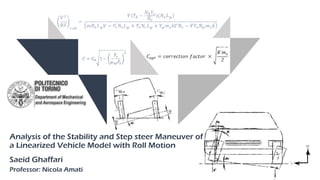
Analysis of the stability and step steer maneuver of a linearized vehicle model with roll motion

Analysis of the lateral dynamics of the vehicle (stability and step steer manoeuvre) of a Linearized vehicle model with roll motion is done in this project. considering a high double wishbone suspension for front and a semi-trailing arm suspension for rear, firstly we derive the roll camber coefficient and camber stiffness benefiting from a multibody dynamics simulation (MSC ADAMS) validated with experimental values. On the other hand, cornering stiffness and aligning moment are computed through the tire diagrams using Carsim software. Root loci of the system with the objective of investigating the vehicle stability as a function of the vehicle speed is plotted with varying the speed V. Furthermore, a step steer manoeuvre will be performed in which the time history of the variables and the trajectory with respect to the rigid vehicle model will be compared. In the last part, the effect of suspension stiffness and damping variation on the vehicle stability will be examined. *Only the first ten pages of the project is presented here; if you are interested to study the rest of this document, please do not hesitate to contact e via saeid.ghaffari@studenti.polito.it.

Recommended
More Related Content
What's hot
What's hot (20)
Similar to Analysis of the stability and step steer maneuver of a linearized vehicle model with roll motion
Similar to Analysis of the stability and step steer maneuver of a linearized vehicle model with roll motion (20)
More from saeid ghaffari
More from saeid ghaffari (7)
Recently uploaded
Recently uploaded (20)
Analysis of the stability and step steer maneuver of a linearized vehicle model with roll motion
- 1. Department of Mechanical and Aerospace Engineering Analysis of the Stability and Step steer Maneuver of a Linearized Vehicle Model with Roll Motion Saeid Ghaffari Professor: Nicola Amati
- 2. 2 Methodology Analysis of the Stability and Step steer Maneuver of a Linearized Vehicle Model with Roll Motion Data set Front suspension characteristics – high DWB Rear suspension characteristics – semi-trailing arm suspension Roll centre height Approaches for defining the front and rear suspension stiffness and damping Dynamic response of the stability analysis (root loci) Study the motion with locked controls of the vehicle following a step steering input
- 3. Chassis Design-A Automotive Engineering - A.Y. 2018-2019 Department of Mechanical and Aerospace Engineering 3 Methodology Characteristic Value (unit) Density of air 1.206 (kg/m3) Front area 2.3 (m2) Lateral aerodynamic force coefficient (𝐶 𝑦) 𝛽 -0.5 Aerodynamic coefficient about z axis (𝐶 𝑀𝑧) 𝛽 -0.05 Starting from a D-class sedan with the following characteristics, we will able to find the requirements of the analysis. Data set Tire Characteristic Value (unit) Cornering stiffness 𝐶1 (front) 144446 (N/rad) Cornering stiffness 𝐶2 (rear) 102764 (N/rad) Camber stiffness 𝐶 𝛾1 (front) -4892 (N/rad) Camber stiffness 𝐶 𝛾2 (rear) -3317 (N/rad) Aligning stiffness 𝑀𝑧1 𝛼 (front) 8978 (Nm/rad) Aligning stiffness 𝑀𝑧2 𝛼 (rear) 8318 (Nm/rad) Real examples: Alfa Romeo 159 Audi A4 BMW 3 series Mercedes-Benz C-Class -120 -100 -80 -60 -40 -20 0 Camberthrustcoefficient(N/deg) Vertical load (N) Analysis of the Stability and Step steer Maneuver of a Linearized Vehicle Model with Roll Motion
- 4. Chassis Design-A Automotive Engineering - A.Y. 2018-2019 Department of Mechanical and Aerospace Engineering 4 Methodology Characteristic Value (unit) Acceleration of gravity 9.81 (m/s2) Sprung mass 1370 (kg) Unsprung mass Front axle 80 (kg) Unsprung mass rear axle 80 (kg) Yaw moment of inertia, 𝑱 𝒛 2315.3 (kgm2) Roll moment of inertia, 𝑱 𝒙 671.3 (kgm2) Mixed moment of inertia, 𝑱 𝒙𝒛 +90 (kgm2) Wheel base 2.780 (m) Front axle to CG 1.110 (m) Height of CG 0.520 (m) Wheel track 1.550 (m) Moments and products of inertia of the unladen sprung mass are very important in our calculations. From CarSim, the moments and product are all taken about the mass center of the sprung mass and are based on a vehicle axis system in which the X axis (longitudinal) and Y axis (lateral) are parallel with the ground when the vehicle is at rest on a flat level surface, and the Z axis (vertical) points up in parallel with the gravity vector; inasmuch as we have no information about 𝑱 𝒙𝒛 , we can use the data related to real cars. Data set Analysis of the Stability and Step steer Maneuver of a Linearized Vehicle Model with Roll Motion
- 5. Chassis Design-A Automotive Engineering - A.Y. 2018-2019 Department of Mechanical and Aerospace Engineering 5 Methodology Front suspension characteristics – high DWB 𝜸 𝟏 𝝋 : front axle camber angle variation with respect to roll angle According to the suspension characteristic obtained from ADAMS/Car analysis, in small roll angle the roll camber coefficient is around + 0.8, which has a good agreement with the literature for this type of suspension. The rate of change in wheel inclination angle with respect to change in vehicle roll angle. By convention, a positive roll angle is a rotation about a longitudinal axis such that the right side moves down and the left, up. Roll Camber coefficient 𝜸 𝟏 𝝋 = 𝟎. 𝟖 The camber change and roll steer depend on the geometry of the suspension system. Analysis of the Stability and Step steer Maneuver of a Linearized Vehicle Model with Roll Motion
- 6. Ref. The Automotive Chassis, Jörnsen Reimpell,Helmut Stoll,Jürgen W. Betzler, chapter 3, page 185 The average roll camber factors for the following axles are: The mean value of the wheel outside of a bend and the inside one together with the kinematic body roll angle gives the roll camber coefficient.
- 7. Chassis Design-A Automotive Engineering - A.Y. 2018-2019 Department of Mechanical and Aerospace Engineering 7 Methodology 𝜹 𝟏 𝝋 : front axle toe angle variation with respect to roll angle Front suspension characteristics – high DWB The rate of change in steer angle with respect to change in vehicle roll angle. A positive roll steer acts in the same direction as the front steering angle, steered by steering wheel, whereas a negative roll steer acts in the opposite direction. From the results obtained from ADAMS/Car in small roll angles, Steady-state cornering with the front and rear roll steer 𝛼 𝑓 and 𝛼 𝑟 Roll Steer 𝜹 𝟏 𝝋 = 𝟎. 𝟒𝟐 Analysis of the Stability and Step steer Maneuver of a Linearized Vehicle Model with Roll Motion
- 8. Chassis Design-A Automotive Engineering - A.Y. 2018-2019 Department of Mechanical and Aerospace Engineering 8 Methodology Rear suspension characteristics – semi-trailing arm suspension 𝜸 𝟐 𝝋 : rear axle camber angle variation with respect to roll angle According to the suspension characteristic obtained from ADAMS/Car analysis, for small roll angle the roll camber coefficient is around + 0.63. Roll Camber coefficient 𝜸 𝟐 𝝋 = 𝟎. 𝟔𝟑 The wheel on the outside of the bend goes into positive camber and the one on the inside into negative camber. Analysis of the Stability and Step steer Maneuver of a Linearized Vehicle Model with Roll Motion
- 9. Chassis Design-A Automotive Engineering - A.Y. 2018-2019 Department of Mechanical and Aerospace Engineering 9 Methodology 𝜹 𝟐 𝝋 : rear axle toe (steer) angle variation with respect to roll angle Rear suspension characteristics – semi-trailing arm suspension From the results obtained from ADAMS/Car in small roll angles, Steady-state cornering with the front and rear roll steer 𝛼 𝑓 and 𝛼 𝑟 Roll Steer 𝜹 𝟐 𝝋 = 𝟎. 𝟎3 Analysis of the Stability and Step steer Maneuver of a Linearized Vehicle Model with Roll Motion
- 10. Chassis Design-A Automotive Engineering - A.Y. 2018-2019 Department of Mechanical and Aerospace Engineering 10 Methodology Roll centre height The position of Roll center changes during roll motion. The roll center is then a fixed point only for small angles about the symmetric position (vanishing roll angle). In the case of large roll angles the roll center, and the roll axis as well, lies outside the symmetry plane of the body. By creating a suspension assembly for front and rear of the same type we introduced before, we can find the roll centre height in static vehicle characteristic (small roll angle). So we can say that the roll centre height of the body in the normal plane passing from the CG is 153 mm. Position Suspension Roll centre height (mm) Rear Semi-trailing arm 77 Front High DWB 204 ℎ = ℎ 𝐶𝐺 − 153 ℎ = 367 𝑚𝑚 Vertical distance from the CG to the roll axis (h) is: Roll centre height is a very important parameter in this study, and increasing the height will increase the risk of vehicle instability. Analysis of the Stability and Step steer Maneuver of a Linearized Vehicle Model with Roll Motion
Editor's Notes
- The roll camber of the wheel has something to do with the Camber stiffness of tire And the roll steer of the wheel has something to do with the cornering stiffness of the tire (in N_phi equation)
- The roll camber of the wheel has something to do with the Camber stiffness of tire And the roll steer of the wheel has something to do with the cornering stiffness of the tire (in N_phi equation)
- +90 Kg.m^2, Inasmuch as we consider +X looking forward.
- Camber angle is positive when the top of the wheel leans outward from the vehicle body
- For independent suspensions, if the roll angle is small, the roll steer can be considered to be proportional to the roll angle (Vehicle Handling Dynamics, Masato Abe).
- For independent suspensions, if the roll angle is small, the roll steer can be considered to be proportional to the roll angle (Vehicle Handling Dynamics, Masato Abe).
- For independent suspensions, if the roll angle is small, the roll steer can be considered to be proportional to the roll angle (Vehicle Handling Dynamics, Masato Abe).