SlideShare a Scribd company logo
1 of 12
1. Strain Gauges:
Strain gauge is a sensor whose resistance changes with the applied force. It convert
force, pressure, tension, weight, etc., into a change in the electrical resistance
which can be measured.
When external force is applied on a stationary object, stress and strain are the
results. Stress is defined as the object's internal resistive force, and strain is
defined as the deformation that occur in an object on the application of loading.
The strain gauge is one of the most momentous sensor of the electrical
measurement technique used for the measurement of mechanical quantities. As the
name indicates, they are used for measuring strain. Strain gauges can be used to
pick up expansion (tensile strain) as well as contraction (compressive strain).
Fig. 1 Strain gauge description Fig. 2 Change in length due to tensile stress
1.1 Gauge Factor:
A fundamental parameter of the strain gage is its sensitivity to strain, quantatively
express as gauge factor (GF). Its the ratio of the fractional change in electrical
resistance to the strain:
In order to drive this equation consider a material whose length is L and area is
termed as A. Then, resistance R is given by:
𝑅 =
𝜌𝐿
𝐴
Upon tensile loading, strain produced will be as follow:
∆𝐿
𝐿
=
𝐿2 − 𝐿1
𝐿
Resistivity (  ) is a constant value and suppose A≈0,
then,
𝑅 ∝ 𝐿
Then,
R L
R L

 
We know:
∆𝐿
𝐿
∝ 𝜀
Where ɛ = Strain produced in the object
1.2 Types:
 Metallic wire-type strain gauge
 Semiconductor Strain Gauges
 Thin-film Strain Gauges
 Diffused Semiconductor Strain Gauges
 45°-Rosette (3 measuring directions)
 90°-Rosette (2 measuring directions)
 Bonded Resistance Gauges Etc.,
While selecting strain gauge we consider its operating temperature, nature of the
strain to be measured and stability requirements.
1.3 Applications:
Strain gauge technology has unlimited uses in numerous fields. It can be used to
test vehicles, ship hulls, dams, and oil drilling platforms. A simple application
of strain gauge technology in civil engineering is to install strain gauges on
structural components in a bridge structure or in a building to measure stress and
compare them with analytical models and calculations. Field-testing requirements
differ from laboratory testing requirements because of multiplex shapes, geometry
and environment. In many cases, new testing devices have to be designed and they
are manufactured to match the criteria of required application. For example, for
measuring changes in soil pressure near an oil-drilling requires custom strain
gauge technology to effectively capture the subtle changes in the pressure
distribution. Furthermore, field usage requires that sensors should be portable, that
the power be available, and the measurements be repeatable.
Strain gauges has numerous applications in aerospace technology, in rail
monitoring etc., .It is mostly found in power plants, ships, refineries,
automobiles and industry at large. Strain gauges may be used in smart bridge
technology to detect structural problems early.
1.4 Advantages:
The strain gauge is accurate, robust and low cost instrument. Strain-gauge based
sensors have advantage of long-term stability. They are operational during the
whole lifetime of the bridge made of stainless steel and it’s not possible to stop
monitoring for recalibration. Timely taken actions can avoid accidents and loss of
life. After installation, the measuring point is covered in order to prevent
damage and electromagnetic interference (EMI).
2. Measuring Strain produced in a simply supported beam by using
strain gauge
In order to calculate the strain produce in steel strain gauge is used. The setup
used in this experiment is composed of three major sections; the simply
supported beam apparatus, instrumentation amplifier and lastly the half arm
Wheatstone bridge. On top and the bottom of the beam two strain gauges are
located. Strain gauge resistance changes by small amounts when it is stretched or
compressed by the deflecting beam on the application of load. Voltage source
powers the gauges, the voltage difference before and during the loading is
measured.
An operational amplifier is used to amplify the output voltage signal from the half
arm Wheatstone bridge so that it can be easily read from table top DMM. These
voltages are the voltages during loading and before loading. To calculate the stress
and strain known masses are attached to the beam and the voltage before and
during the loading would be recorded. Stress and Strain can be found by using
following formula:
In the first eq. M is the applied moment, y is the distance from the centroid to the
top or the bottom fibers and I is the moment of inertia of the cross section.
In second eq. the δEo is the difference in loaded voltage. The Vin is the voltage
supplied to the Wheatstone bridge and GF is the gauge factor supplied by the
manufacturer. Lastly the G is the gain of operational amplifier.
Young’s Modulus of beam material can also be find within elastic limit by
following formula:
𝐸 =
𝜎
𝜀
There might be error in final results and the problem usually lies in the Op.
Amplifier because the voltage readings don’t stop fluctuating by significant
amounts.
2.1 Procedure:
Place a load of 2lb. in order to remove the wrinkles in the wire. Then with the help
of strain gauge, determine resistance of the wire. Now, place 5lb. load and note
readings. Repeat above experiment and note more readings. After doing that
unload loading carefully and note unloading values as well.
3. Measuring Elongation of a wire when tensile loading is applied by
strain gauge:
Elongation produce in a metallic wire upon tensile loading can be measured by
using strain gauges.
3.1 Setup:
In this application the instrument is adhered to the round metallic wire to measure
the stress in the direction of loading. This set up ensures that the maximum stress
concentration (and the maximal uniformity of this) is on the center portion.
3.2 Procedure:
 Firstly, measure width and thickness of the wire and record it.
 Calculate maximum allowable load depend on estimated proportional limit of
the metallic wire.
 Determine the accuracy. Note the difference in weights between scale reading
and the actual weight and adjust all the future weight loadings by this
difference.
 Next, measure the applied forces. Make sure that the forces are less than the
previously calculated maximum allowable load.
 Now, set up a strain indicator by using Quarter Bridge for both strain gauges
and check all the dimensions, balance the reading before the test and apply load
while recording gauge data for each load.
By this given method stress and strain can be calculated. Hook’s law can also be
verified by the measurements taken with the help of strain gauge.
General formula for calculating strain is
𝜀 =
∆𝑠 − ∆𝑠′
∆𝑠
Where ∆𝑠′
is change in length of a wire and ∆𝑠 is original length of the wire.
4. Bridge Structure:
A bridge is a structure that is built to span a physical hurdle, such as a body of
water, valley, or a road, without closing the way underneath. It is constructed to
provide a passage over the obstacle that can disturb and slow normal working of
life.
4.1 Parts of a bridge:
 Abutment(support at both end of a bridge)
 Pile(generally needed when upper soil layer is loose)
 Pier(compression member)
 Girder(Just like beam)
 Deck(Fundamental part of a bridge, bed)
 Rail Track(passage; for railway bridges)
4.2 Types of Bridges:
 Truss bridge
 Arch bridge
 Suspension Bridge
 Slab bridge
 Box Girder bridge
 Cable stayed bridge and etc.
4.3 Footbridge:
Footbridges are required where a separate pathway has to be provided to cross the
traffic flows or some physical obstacle in the way, such as a river. The loads they
bear are quite modest as compared to highway or railway bridges, and in most of
the cases a fairly light structure is required. However, they are frequently required
to give a long span and stiffness.
In the given project we are going to choose Truss footbridge because it’s a strong
and reliable structure.
4.3.1 Truss Bridge:
Trusses offer a light but strong and economical form of construction, especially
when the span is large. Members of a truss can be quite slender which naturally
leads to the use of structural hollow sections. Hollow sections have been used for
the construction of footbridges for over 50 years and some professionals have
specialized in this form of construction to develop techniques and details which
they will utilize to the best advantage.
Trusses for footbridges are normally scheduled with a deck at the level of bottom
chord, either in through or half-through construction. Half-through construction is
normally used for the spans small in length, where the required depth is less than
the clearance height for the people to walk through. For large spans, through
construction is used.
The type of truss usually practiced is either Warren truss or modified Warren truss.
Warren trusses are the simplest type of truss, with all the load being carried as
axial load in the members and minimum of the members meeting at joints.
However, the loads which are transfer to the bottom chords from the passageway
floor can lead to significant bending in these members when the panels are large
enough. A modified Warren truss lessens the span of the chord members, though
additional vertical members, enumerate complexity to the fabrication.
5. Strain gauge use in bridges:
Bridges are generally thought of as static structures. But in fact they act more like
dynamic. They constantly vary, responding to different loads, weather patterns etc.
Due to excessive loading, stress and strains are produced in bridge structure which
badly affect the structure and eventually destroy the bridge structure. In order to
prevent this instrumentation of bridges is done to verify the design parameters, to
evaluate the functioning of new technologies used, to verify and control the
construction process and for regular performance monitoring. Well-instrumented
bridges can alert responsible authorities about approaching failure so as to instigate
preventive measures.
In bridge structure strain gauges have been used which are attached directly to
the structural members of the bridge or as a sensing element in the force sensors.
The gauge position will be adjusted in such a manner that the gauge wires are
aligned across the direction of the strain to be measured.
5.1 Working:
When force is applied on the wire, there occurs a strain (consider tensile, within
elastic limit) that increases the length and in turn decreases its area. Thus, the
resistance of the wire varies. This change in resistance is proportional to the strain
produced and measured using a Wheatstone bridge. Stress is measured indirectly
and its variation with time, quantitatively. Change in stress is determined by
multiplying the strain measured by the modulus of elasticity.
6. Given problem:
We are given with a footbridge under working for which we have to choose
suitable material for construction such that upon loading it will undergo a
deflection whose value should not exceed 0.1m.
Given Data:
Length of span L= (500+47)/10m=54.7m
Max. Allowable deflection= 0.1m
Average weight of a person= 70kg
Assumptions:
 Assume that concerete is the constructing material as it is strong and durable
and ensures strength and safety.
Youngs Modulus E =32 × 109
Pa and Density 𝜌 = 2300kg/𝑚3
 Width w =1.5m
 Height h =4.5m
Analysis and Calculations:
Then Moment of inertia of cross sectional area:
𝐼 = 𝑏ℎ3
/12
𝐼 =
1
12
× 1.5 × (4.5)3
𝐼 = 11.4𝑚4
As Mass is
𝑚 = 𝜌𝑉
𝑚 = 𝜌(𝐿 × 𝑤 × ℎ)
𝑚 = 2300 × 54.7 × 1.5 × 4.5
𝑚 = 85 × 104
kg
Now, to find weight of the beam we will apply a fundamental formula:
𝑊 = 𝑚𝑔
𝑊 = 56.6 × 104
kg × 9.81m/𝑠−2
𝑊 = 8.33 × 10⁶
N
Now,
𝐸 = (𝑊
𝛿𝑐
⁄ ) (𝐿3
48𝐼
⁄ )
𝛿𝑐 =
𝑊𝐿3
𝐸48𝐼
𝛿𝑐 =
8.33 × 106
× (54.7)3
32 × 109 × 48 × 11.4
𝛿𝑐 =
1.36 × 10¹²
1.75 × 10¹³
𝛿𝑐 = 0.077𝑚 (Less than 𝛿 = 0.1𝑚)
As
𝛿𝑐 < 𝛿
Hence proved the assumption we made are feasible.
Analysis and Calculations:
We are given with average weight of a person. To find out effective load on the
beam we will use following relation:
Type equation here.
𝐸 = (𝑊
𝛿𝑐
⁄ ) (𝐿3
48𝐼
⁄ )
𝑊 =
48𝐼𝛿𝑐𝐸
𝐿3
𝑊 =
48 × 0.1 × 200 × 106
54.73

More Related Content

Similar to Strain Gauges (Autosaved).docx

Strain Measurement.pdf
Strain Measurement.pdfStrain Measurement.pdf
Strain Measurement.pdfGopalakrishnaU
 
Measuring Forces in the Force Shunt
Measuring Forces in the Force ShuntMeasuring Forces in the Force Shunt
Measuring Forces in the Force ShuntTacuna Systems
 
Introduction to-strain-gauges-and-their-usage
Introduction to-strain-gauges-and-their-usageIntroduction to-strain-gauges-and-their-usage
Introduction to-strain-gauges-and-their-usageAli Abd Ellatief
 
Strength of materials_laboratory
Strength of materials_laboratoryStrength of materials_laboratory
Strength of materials_laboratorysudheerchekka1
 
Wheel-rail Interaction Loads Test.pdf
Wheel-rail Interaction Loads Test.pdfWheel-rail Interaction Loads Test.pdf
Wheel-rail Interaction Loads Test.pdfAsSyaffResources
 
Determination of physical properties of steel, ductility etc
Determination of physical properties of steel, ductility etcDetermination of physical properties of steel, ductility etc
Determination of physical properties of steel, ductility etcSoniaVerma71
 
INTRODUCTION TO STRAIN GAUGES
INTRODUCTION TO STRAIN GAUGESINTRODUCTION TO STRAIN GAUGES
INTRODUCTION TO STRAIN GAUGESSACHINNikam39
 
Mechanical properties
Mechanical propertiesMechanical properties
Mechanical propertiesYatin Singh
 
Basic civil mechanical Engineering lab manual according to JNTU annathapur sy...
Basic civil mechanical Engineering lab manual according to JNTU annathapur sy...Basic civil mechanical Engineering lab manual according to JNTU annathapur sy...
Basic civil mechanical Engineering lab manual according to JNTU annathapur sy...MOKSHIT TECH
 
Design and analysis of stress ribbon bridges
Design and analysis of stress ribbon bridgesDesign and analysis of stress ribbon bridges
Design and analysis of stress ribbon bridgeseSAT Journals
 
Design and analysis of stress ribbon bridges
Design and analysis of stress ribbon bridgesDesign and analysis of stress ribbon bridges
Design and analysis of stress ribbon bridgeseSAT Journals
 
STARIN GAUGE.pdf
STARIN GAUGE.pdfSTARIN GAUGE.pdf
STARIN GAUGE.pdfSivaGovind2
 
1658821432126_Strain Gauges PPT-2.pptx
1658821432126_Strain Gauges PPT-2.pptx1658821432126_Strain Gauges PPT-2.pptx
1658821432126_Strain Gauges PPT-2.pptxShreyasshreyu14
 
STRAIN GAUGE - Unit3 Presentation.pptx
STRAIN GAUGE - Unit3 Presentation.pptxSTRAIN GAUGE - Unit3 Presentation.pptx
STRAIN GAUGE - Unit3 Presentation.pptxsharmeejeyam
 
torque measuring instruments and force measuring instruments
torque measuring instruments and force measuring instruments torque measuring instruments and force measuring instruments
torque measuring instruments and force measuring instruments Rangeshkanoujiya
 

Similar to Strain Gauges (Autosaved).docx (20)

Strain Measurement.pdf
Strain Measurement.pdfStrain Measurement.pdf
Strain Measurement.pdf
 
Measuring Forces in the Force Shunt
Measuring Forces in the Force ShuntMeasuring Forces in the Force Shunt
Measuring Forces in the Force Shunt
 
Introduction to-strain-gauges-and-their-usage
Introduction to-strain-gauges-and-their-usageIntroduction to-strain-gauges-and-their-usage
Introduction to-strain-gauges-and-their-usage
 
Strength of materials_laboratory
Strength of materials_laboratoryStrength of materials_laboratory
Strength of materials_laboratory
 
Transducer main
Transducer mainTransducer main
Transducer main
 
Wheel-rail Interaction Loads Test.pdf
Wheel-rail Interaction Loads Test.pdfWheel-rail Interaction Loads Test.pdf
Wheel-rail Interaction Loads Test.pdf
 
Determination of physical properties of steel, ductility etc
Determination of physical properties of steel, ductility etcDetermination of physical properties of steel, ductility etc
Determination of physical properties of steel, ductility etc
 
Strain measurement
Strain measurementStrain measurement
Strain measurement
 
Resistive Sensors
Resistive SensorsResistive Sensors
Resistive Sensors
 
INTRODUCTION TO STRAIN GAUGES
INTRODUCTION TO STRAIN GAUGESINTRODUCTION TO STRAIN GAUGES
INTRODUCTION TO STRAIN GAUGES
 
Mechanical properties
Mechanical propertiesMechanical properties
Mechanical properties
 
Basic civil mechanical Engineering lab manual according to JNTU annathapur sy...
Basic civil mechanical Engineering lab manual according to JNTU annathapur sy...Basic civil mechanical Engineering lab manual according to JNTU annathapur sy...
Basic civil mechanical Engineering lab manual according to JNTU annathapur sy...
 
Presentation11-1.ppt
Presentation11-1.pptPresentation11-1.ppt
Presentation11-1.ppt
 
Design and analysis of stress ribbon bridges
Design and analysis of stress ribbon bridgesDesign and analysis of stress ribbon bridges
Design and analysis of stress ribbon bridges
 
Design and analysis of stress ribbon bridges
Design and analysis of stress ribbon bridgesDesign and analysis of stress ribbon bridges
Design and analysis of stress ribbon bridges
 
Tensile
TensileTensile
Tensile
 
STARIN GAUGE.pdf
STARIN GAUGE.pdfSTARIN GAUGE.pdf
STARIN GAUGE.pdf
 
1658821432126_Strain Gauges PPT-2.pptx
1658821432126_Strain Gauges PPT-2.pptx1658821432126_Strain Gauges PPT-2.pptx
1658821432126_Strain Gauges PPT-2.pptx
 
STRAIN GAUGE - Unit3 Presentation.pptx
STRAIN GAUGE - Unit3 Presentation.pptxSTRAIN GAUGE - Unit3 Presentation.pptx
STRAIN GAUGE - Unit3 Presentation.pptx
 
torque measuring instruments and force measuring instruments
torque measuring instruments and force measuring instruments torque measuring instruments and force measuring instruments
torque measuring instruments and force measuring instruments
 

Recently uploaded

High Profile Call Girls Nagpur Isha Call 7001035870 Meet With Nagpur Escorts
High Profile Call Girls Nagpur Isha Call 7001035870 Meet With Nagpur EscortsHigh Profile Call Girls Nagpur Isha Call 7001035870 Meet With Nagpur Escorts
High Profile Call Girls Nagpur Isha Call 7001035870 Meet With Nagpur Escortsranjana rawat
 
Glass Ceramics: Processing and Properties
Glass Ceramics: Processing and PropertiesGlass Ceramics: Processing and Properties
Glass Ceramics: Processing and PropertiesPrabhanshu Chaturvedi
 
The Most Attractive Pune Call Girls Budhwar Peth 8250192130 Will You Miss Thi...
The Most Attractive Pune Call Girls Budhwar Peth 8250192130 Will You Miss Thi...The Most Attractive Pune Call Girls Budhwar Peth 8250192130 Will You Miss Thi...
The Most Attractive Pune Call Girls Budhwar Peth 8250192130 Will You Miss Thi...ranjana rawat
 
UNIT-II FMM-Flow Through Circular Conduits
UNIT-II FMM-Flow Through Circular ConduitsUNIT-II FMM-Flow Through Circular Conduits
UNIT-II FMM-Flow Through Circular Conduitsrknatarajan
 
The Most Attractive Pune Call Girls Manchar 8250192130 Will You Miss This Cha...
The Most Attractive Pune Call Girls Manchar 8250192130 Will You Miss This Cha...The Most Attractive Pune Call Girls Manchar 8250192130 Will You Miss This Cha...
The Most Attractive Pune Call Girls Manchar 8250192130 Will You Miss This Cha...ranjana rawat
 
Introduction and different types of Ethernet.pptx
Introduction and different types of Ethernet.pptxIntroduction and different types of Ethernet.pptx
Introduction and different types of Ethernet.pptxupamatechverse
 
Booking open Available Pune Call Girls Pargaon 6297143586 Call Hot Indian Gi...
Booking open Available Pune Call Girls Pargaon  6297143586 Call Hot Indian Gi...Booking open Available Pune Call Girls Pargaon  6297143586 Call Hot Indian Gi...
Booking open Available Pune Call Girls Pargaon 6297143586 Call Hot Indian Gi...Call Girls in Nagpur High Profile
 
MANUFACTURING PROCESS-II UNIT-5 NC MACHINE TOOLS
MANUFACTURING PROCESS-II UNIT-5 NC MACHINE TOOLSMANUFACTURING PROCESS-II UNIT-5 NC MACHINE TOOLS
MANUFACTURING PROCESS-II UNIT-5 NC MACHINE TOOLSSIVASHANKAR N
 
Structural Analysis and Design of Foundations: A Comprehensive Handbook for S...
Structural Analysis and Design of Foundations: A Comprehensive Handbook for S...Structural Analysis and Design of Foundations: A Comprehensive Handbook for S...
Structural Analysis and Design of Foundations: A Comprehensive Handbook for S...Dr.Costas Sachpazis
 
KubeKraft presentation @CloudNativeHooghly
KubeKraft presentation @CloudNativeHooghlyKubeKraft presentation @CloudNativeHooghly
KubeKraft presentation @CloudNativeHooghlysanyuktamishra911
 
Introduction to Multiple Access Protocol.pptx
Introduction to Multiple Access Protocol.pptxIntroduction to Multiple Access Protocol.pptx
Introduction to Multiple Access Protocol.pptxupamatechverse
 
Call Girls Service Nashik Vaishnavi 7001305949 Independent Escort Service Nashik
Call Girls Service Nashik Vaishnavi 7001305949 Independent Escort Service NashikCall Girls Service Nashik Vaishnavi 7001305949 Independent Escort Service Nashik
Call Girls Service Nashik Vaishnavi 7001305949 Independent Escort Service NashikCall Girls in Nagpur High Profile
 
Online banking management system project.pdf
Online banking management system project.pdfOnline banking management system project.pdf
Online banking management system project.pdfKamal Acharya
 
(SHREYA) Chakan Call Girls Just Call 7001035870 [ Cash on Delivery ] Pune Esc...
(SHREYA) Chakan Call Girls Just Call 7001035870 [ Cash on Delivery ] Pune Esc...(SHREYA) Chakan Call Girls Just Call 7001035870 [ Cash on Delivery ] Pune Esc...
(SHREYA) Chakan Call Girls Just Call 7001035870 [ Cash on Delivery ] Pune Esc...ranjana rawat
 
UNIT - IV - Air Compressors and its Performance
UNIT - IV - Air Compressors and its PerformanceUNIT - IV - Air Compressors and its Performance
UNIT - IV - Air Compressors and its Performancesivaprakash250
 
VIP Call Girls Ankleshwar 7001035870 Whatsapp Number, 24/07 Booking
VIP Call Girls Ankleshwar 7001035870 Whatsapp Number, 24/07 BookingVIP Call Girls Ankleshwar 7001035870 Whatsapp Number, 24/07 Booking
VIP Call Girls Ankleshwar 7001035870 Whatsapp Number, 24/07 Bookingdharasingh5698
 
UNIT-III FMM. DIMENSIONAL ANALYSIS
UNIT-III FMM.        DIMENSIONAL ANALYSISUNIT-III FMM.        DIMENSIONAL ANALYSIS
UNIT-III FMM. DIMENSIONAL ANALYSISrknatarajan
 
Call Girls Service Nagpur Tanvi Call 7001035870 Meet With Nagpur Escorts
Call Girls Service Nagpur Tanvi Call 7001035870 Meet With Nagpur EscortsCall Girls Service Nagpur Tanvi Call 7001035870 Meet With Nagpur Escorts
Call Girls Service Nagpur Tanvi Call 7001035870 Meet With Nagpur EscortsCall Girls in Nagpur High Profile
 
(ANJALI) Dange Chowk Call Girls Just Call 7001035870 [ Cash on Delivery ] Pun...
(ANJALI) Dange Chowk Call Girls Just Call 7001035870 [ Cash on Delivery ] Pun...(ANJALI) Dange Chowk Call Girls Just Call 7001035870 [ Cash on Delivery ] Pun...
(ANJALI) Dange Chowk Call Girls Just Call 7001035870 [ Cash on Delivery ] Pun...ranjana rawat
 

Recently uploaded (20)

High Profile Call Girls Nagpur Isha Call 7001035870 Meet With Nagpur Escorts
High Profile Call Girls Nagpur Isha Call 7001035870 Meet With Nagpur EscortsHigh Profile Call Girls Nagpur Isha Call 7001035870 Meet With Nagpur Escorts
High Profile Call Girls Nagpur Isha Call 7001035870 Meet With Nagpur Escorts
 
Glass Ceramics: Processing and Properties
Glass Ceramics: Processing and PropertiesGlass Ceramics: Processing and Properties
Glass Ceramics: Processing and Properties
 
The Most Attractive Pune Call Girls Budhwar Peth 8250192130 Will You Miss Thi...
The Most Attractive Pune Call Girls Budhwar Peth 8250192130 Will You Miss Thi...The Most Attractive Pune Call Girls Budhwar Peth 8250192130 Will You Miss Thi...
The Most Attractive Pune Call Girls Budhwar Peth 8250192130 Will You Miss Thi...
 
UNIT-II FMM-Flow Through Circular Conduits
UNIT-II FMM-Flow Through Circular ConduitsUNIT-II FMM-Flow Through Circular Conduits
UNIT-II FMM-Flow Through Circular Conduits
 
The Most Attractive Pune Call Girls Manchar 8250192130 Will You Miss This Cha...
The Most Attractive Pune Call Girls Manchar 8250192130 Will You Miss This Cha...The Most Attractive Pune Call Girls Manchar 8250192130 Will You Miss This Cha...
The Most Attractive Pune Call Girls Manchar 8250192130 Will You Miss This Cha...
 
Introduction and different types of Ethernet.pptx
Introduction and different types of Ethernet.pptxIntroduction and different types of Ethernet.pptx
Introduction and different types of Ethernet.pptx
 
Booking open Available Pune Call Girls Pargaon 6297143586 Call Hot Indian Gi...
Booking open Available Pune Call Girls Pargaon  6297143586 Call Hot Indian Gi...Booking open Available Pune Call Girls Pargaon  6297143586 Call Hot Indian Gi...
Booking open Available Pune Call Girls Pargaon 6297143586 Call Hot Indian Gi...
 
MANUFACTURING PROCESS-II UNIT-5 NC MACHINE TOOLS
MANUFACTURING PROCESS-II UNIT-5 NC MACHINE TOOLSMANUFACTURING PROCESS-II UNIT-5 NC MACHINE TOOLS
MANUFACTURING PROCESS-II UNIT-5 NC MACHINE TOOLS
 
Structural Analysis and Design of Foundations: A Comprehensive Handbook for S...
Structural Analysis and Design of Foundations: A Comprehensive Handbook for S...Structural Analysis and Design of Foundations: A Comprehensive Handbook for S...
Structural Analysis and Design of Foundations: A Comprehensive Handbook for S...
 
Roadmap to Membership of RICS - Pathways and Routes
Roadmap to Membership of RICS - Pathways and RoutesRoadmap to Membership of RICS - Pathways and Routes
Roadmap to Membership of RICS - Pathways and Routes
 
KubeKraft presentation @CloudNativeHooghly
KubeKraft presentation @CloudNativeHooghlyKubeKraft presentation @CloudNativeHooghly
KubeKraft presentation @CloudNativeHooghly
 
Introduction to Multiple Access Protocol.pptx
Introduction to Multiple Access Protocol.pptxIntroduction to Multiple Access Protocol.pptx
Introduction to Multiple Access Protocol.pptx
 
Call Girls Service Nashik Vaishnavi 7001305949 Independent Escort Service Nashik
Call Girls Service Nashik Vaishnavi 7001305949 Independent Escort Service NashikCall Girls Service Nashik Vaishnavi 7001305949 Independent Escort Service Nashik
Call Girls Service Nashik Vaishnavi 7001305949 Independent Escort Service Nashik
 
Online banking management system project.pdf
Online banking management system project.pdfOnline banking management system project.pdf
Online banking management system project.pdf
 
(SHREYA) Chakan Call Girls Just Call 7001035870 [ Cash on Delivery ] Pune Esc...
(SHREYA) Chakan Call Girls Just Call 7001035870 [ Cash on Delivery ] Pune Esc...(SHREYA) Chakan Call Girls Just Call 7001035870 [ Cash on Delivery ] Pune Esc...
(SHREYA) Chakan Call Girls Just Call 7001035870 [ Cash on Delivery ] Pune Esc...
 
UNIT - IV - Air Compressors and its Performance
UNIT - IV - Air Compressors and its PerformanceUNIT - IV - Air Compressors and its Performance
UNIT - IV - Air Compressors and its Performance
 
VIP Call Girls Ankleshwar 7001035870 Whatsapp Number, 24/07 Booking
VIP Call Girls Ankleshwar 7001035870 Whatsapp Number, 24/07 BookingVIP Call Girls Ankleshwar 7001035870 Whatsapp Number, 24/07 Booking
VIP Call Girls Ankleshwar 7001035870 Whatsapp Number, 24/07 Booking
 
UNIT-III FMM. DIMENSIONAL ANALYSIS
UNIT-III FMM.        DIMENSIONAL ANALYSISUNIT-III FMM.        DIMENSIONAL ANALYSIS
UNIT-III FMM. DIMENSIONAL ANALYSIS
 
Call Girls Service Nagpur Tanvi Call 7001035870 Meet With Nagpur Escorts
Call Girls Service Nagpur Tanvi Call 7001035870 Meet With Nagpur EscortsCall Girls Service Nagpur Tanvi Call 7001035870 Meet With Nagpur Escorts
Call Girls Service Nagpur Tanvi Call 7001035870 Meet With Nagpur Escorts
 
(ANJALI) Dange Chowk Call Girls Just Call 7001035870 [ Cash on Delivery ] Pun...
(ANJALI) Dange Chowk Call Girls Just Call 7001035870 [ Cash on Delivery ] Pun...(ANJALI) Dange Chowk Call Girls Just Call 7001035870 [ Cash on Delivery ] Pun...
(ANJALI) Dange Chowk Call Girls Just Call 7001035870 [ Cash on Delivery ] Pun...
 

Strain Gauges (Autosaved).docx

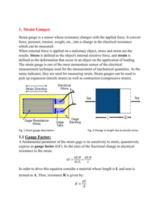
  • 1. 1. Strain Gauges: Strain gauge is a sensor whose resistance changes with the applied force. It convert force, pressure, tension, weight, etc., into a change in the electrical resistance which can be measured. When external force is applied on a stationary object, stress and strain are the results. Stress is defined as the object's internal resistive force, and strain is defined as the deformation that occur in an object on the application of loading. The strain gauge is one of the most momentous sensor of the electrical measurement technique used for the measurement of mechanical quantities. As the name indicates, they are used for measuring strain. Strain gauges can be used to pick up expansion (tensile strain) as well as contraction (compressive strain). Fig. 1 Strain gauge description Fig. 2 Change in length due to tensile stress 1.1 Gauge Factor: A fundamental parameter of the strain gage is its sensitivity to strain, quantatively express as gauge factor (GF). Its the ratio of the fractional change in electrical resistance to the strain: In order to drive this equation consider a material whose length is L and area is termed as A. Then, resistance R is given by: 𝑅 = 𝜌𝐿 𝐴
  • 2. Upon tensile loading, strain produced will be as follow: ∆𝐿 𝐿 = 𝐿2 − 𝐿1 𝐿 Resistivity (  ) is a constant value and suppose A≈0, then, 𝑅 ∝ 𝐿 Then, R L R L    We know: ∆𝐿 𝐿 ∝ 𝜀 Where ɛ = Strain produced in the object 1.2 Types:  Metallic wire-type strain gauge  Semiconductor Strain Gauges  Thin-film Strain Gauges  Diffused Semiconductor Strain Gauges  45°-Rosette (3 measuring directions)  90°-Rosette (2 measuring directions)  Bonded Resistance Gauges Etc., While selecting strain gauge we consider its operating temperature, nature of the strain to be measured and stability requirements. 1.3 Applications: Strain gauge technology has unlimited uses in numerous fields. It can be used to test vehicles, ship hulls, dams, and oil drilling platforms. A simple application of strain gauge technology in civil engineering is to install strain gauges on
  • 3. structural components in a bridge structure or in a building to measure stress and compare them with analytical models and calculations. Field-testing requirements differ from laboratory testing requirements because of multiplex shapes, geometry and environment. In many cases, new testing devices have to be designed and they are manufactured to match the criteria of required application. For example, for measuring changes in soil pressure near an oil-drilling requires custom strain gauge technology to effectively capture the subtle changes in the pressure distribution. Furthermore, field usage requires that sensors should be portable, that the power be available, and the measurements be repeatable. Strain gauges has numerous applications in aerospace technology, in rail monitoring etc., .It is mostly found in power plants, ships, refineries, automobiles and industry at large. Strain gauges may be used in smart bridge technology to detect structural problems early. 1.4 Advantages: The strain gauge is accurate, robust and low cost instrument. Strain-gauge based sensors have advantage of long-term stability. They are operational during the whole lifetime of the bridge made of stainless steel and it’s not possible to stop monitoring for recalibration. Timely taken actions can avoid accidents and loss of life. After installation, the measuring point is covered in order to prevent damage and electromagnetic interference (EMI). 2. Measuring Strain produced in a simply supported beam by using strain gauge In order to calculate the strain produce in steel strain gauge is used. The setup used in this experiment is composed of three major sections; the simply supported beam apparatus, instrumentation amplifier and lastly the half arm Wheatstone bridge. On top and the bottom of the beam two strain gauges are located. Strain gauge resistance changes by small amounts when it is stretched or compressed by the deflecting beam on the application of load. Voltage source powers the gauges, the voltage difference before and during the loading is measured.
  • 4. An operational amplifier is used to amplify the output voltage signal from the half arm Wheatstone bridge so that it can be easily read from table top DMM. These voltages are the voltages during loading and before loading. To calculate the stress and strain known masses are attached to the beam and the voltage before and during the loading would be recorded. Stress and Strain can be found by using following formula: In the first eq. M is the applied moment, y is the distance from the centroid to the top or the bottom fibers and I is the moment of inertia of the cross section. In second eq. the δEo is the difference in loaded voltage. The Vin is the voltage supplied to the Wheatstone bridge and GF is the gauge factor supplied by the manufacturer. Lastly the G is the gain of operational amplifier. Young’s Modulus of beam material can also be find within elastic limit by following formula: 𝐸 = 𝜎 𝜀 There might be error in final results and the problem usually lies in the Op. Amplifier because the voltage readings don’t stop fluctuating by significant amounts. 2.1 Procedure: Place a load of 2lb. in order to remove the wrinkles in the wire. Then with the help of strain gauge, determine resistance of the wire. Now, place 5lb. load and note
  • 5. readings. Repeat above experiment and note more readings. After doing that unload loading carefully and note unloading values as well. 3. Measuring Elongation of a wire when tensile loading is applied by strain gauge: Elongation produce in a metallic wire upon tensile loading can be measured by using strain gauges. 3.1 Setup: In this application the instrument is adhered to the round metallic wire to measure the stress in the direction of loading. This set up ensures that the maximum stress concentration (and the maximal uniformity of this) is on the center portion. 3.2 Procedure:  Firstly, measure width and thickness of the wire and record it.  Calculate maximum allowable load depend on estimated proportional limit of the metallic wire.  Determine the accuracy. Note the difference in weights between scale reading and the actual weight and adjust all the future weight loadings by this difference.  Next, measure the applied forces. Make sure that the forces are less than the previously calculated maximum allowable load.  Now, set up a strain indicator by using Quarter Bridge for both strain gauges and check all the dimensions, balance the reading before the test and apply load while recording gauge data for each load. By this given method stress and strain can be calculated. Hook’s law can also be verified by the measurements taken with the help of strain gauge.
  • 6. General formula for calculating strain is 𝜀 = ∆𝑠 − ∆𝑠′ ∆𝑠 Where ∆𝑠′ is change in length of a wire and ∆𝑠 is original length of the wire. 4. Bridge Structure: A bridge is a structure that is built to span a physical hurdle, such as a body of water, valley, or a road, without closing the way underneath. It is constructed to provide a passage over the obstacle that can disturb and slow normal working of life. 4.1 Parts of a bridge:  Abutment(support at both end of a bridge)  Pile(generally needed when upper soil layer is loose)  Pier(compression member)  Girder(Just like beam)  Deck(Fundamental part of a bridge, bed)  Rail Track(passage; for railway bridges)
  • 7. 4.2 Types of Bridges:  Truss bridge  Arch bridge  Suspension Bridge  Slab bridge  Box Girder bridge  Cable stayed bridge and etc. 4.3 Footbridge: Footbridges are required where a separate pathway has to be provided to cross the traffic flows or some physical obstacle in the way, such as a river. The loads they bear are quite modest as compared to highway or railway bridges, and in most of the cases a fairly light structure is required. However, they are frequently required to give a long span and stiffness. In the given project we are going to choose Truss footbridge because it’s a strong and reliable structure. 4.3.1 Truss Bridge: Trusses offer a light but strong and economical form of construction, especially when the span is large. Members of a truss can be quite slender which naturally leads to the use of structural hollow sections. Hollow sections have been used for the construction of footbridges for over 50 years and some professionals have specialized in this form of construction to develop techniques and details which they will utilize to the best advantage.
  • 8. Trusses for footbridges are normally scheduled with a deck at the level of bottom chord, either in through or half-through construction. Half-through construction is normally used for the spans small in length, where the required depth is less than the clearance height for the people to walk through. For large spans, through construction is used. The type of truss usually practiced is either Warren truss or modified Warren truss. Warren trusses are the simplest type of truss, with all the load being carried as axial load in the members and minimum of the members meeting at joints. However, the loads which are transfer to the bottom chords from the passageway floor can lead to significant bending in these members when the panels are large enough. A modified Warren truss lessens the span of the chord members, though additional vertical members, enumerate complexity to the fabrication.
  • 9. 5. Strain gauge use in bridges: Bridges are generally thought of as static structures. But in fact they act more like dynamic. They constantly vary, responding to different loads, weather patterns etc. Due to excessive loading, stress and strains are produced in bridge structure which badly affect the structure and eventually destroy the bridge structure. In order to prevent this instrumentation of bridges is done to verify the design parameters, to evaluate the functioning of new technologies used, to verify and control the construction process and for regular performance monitoring. Well-instrumented bridges can alert responsible authorities about approaching failure so as to instigate preventive measures. In bridge structure strain gauges have been used which are attached directly to the structural members of the bridge or as a sensing element in the force sensors. The gauge position will be adjusted in such a manner that the gauge wires are aligned across the direction of the strain to be measured. 5.1 Working: When force is applied on the wire, there occurs a strain (consider tensile, within elastic limit) that increases the length and in turn decreases its area. Thus, the resistance of the wire varies. This change in resistance is proportional to the strain produced and measured using a Wheatstone bridge. Stress is measured indirectly and its variation with time, quantitatively. Change in stress is determined by multiplying the strain measured by the modulus of elasticity.
  • 10. 6. Given problem: We are given with a footbridge under working for which we have to choose suitable material for construction such that upon loading it will undergo a deflection whose value should not exceed 0.1m. Given Data: Length of span L= (500+47)/10m=54.7m Max. Allowable deflection= 0.1m Average weight of a person= 70kg Assumptions:  Assume that concerete is the constructing material as it is strong and durable and ensures strength and safety. Youngs Modulus E =32 × 109 Pa and Density 𝜌 = 2300kg/𝑚3  Width w =1.5m  Height h =4.5m Analysis and Calculations: Then Moment of inertia of cross sectional area: 𝐼 = 𝑏ℎ3 /12
  • 11. 𝐼 = 1 12 × 1.5 × (4.5)3 𝐼 = 11.4𝑚4 As Mass is 𝑚 = 𝜌𝑉 𝑚 = 𝜌(𝐿 × 𝑤 × ℎ) 𝑚 = 2300 × 54.7 × 1.5 × 4.5 𝑚 = 85 × 104 kg Now, to find weight of the beam we will apply a fundamental formula: 𝑊 = 𝑚𝑔 𝑊 = 56.6 × 104 kg × 9.81m/𝑠−2 𝑊 = 8.33 × 10⁶ N Now, 𝐸 = (𝑊 𝛿𝑐 ⁄ ) (𝐿3 48𝐼 ⁄ ) 𝛿𝑐 = 𝑊𝐿3 𝐸48𝐼 𝛿𝑐 = 8.33 × 106 × (54.7)3 32 × 109 × 48 × 11.4 𝛿𝑐 = 1.36 × 10¹² 1.75 × 10¹³ 𝛿𝑐 = 0.077𝑚 (Less than 𝛿 = 0.1𝑚) As 𝛿𝑐 < 𝛿 Hence proved the assumption we made are feasible. Analysis and Calculations:
  • 12. We are given with average weight of a person. To find out effective load on the beam we will use following relation: Type equation here. 𝐸 = (𝑊 𝛿𝑐 ⁄ ) (𝐿3 48𝐼 ⁄ ) 𝑊 = 48𝐼𝛿𝑐𝐸 𝐿3 𝑊 = 48 × 0.1 × 200 × 106 54.73