The document provides instructions for configuring an Avaya IP Office phone system in a lab environment without physical hardware. It includes steps to configure the system settings, extensions, users, and soft features using the IP Office Manager interface. The basic system configuration includes settings like the system name, IP addresses, DNS and voice mail settings. Extensions are created and assigned IP addresses and users are linked to extensions. Finally, soft features are configured using short codes to enable features like call waiting and call forwarding for the phone system.
NETW250 Week 2 iLab Avaya IP Office Phone SystemIntroduction.docx
1. NETW250 Week 2 iLab: Avaya IP Office Phone System
Introduction
In this lab, you will access the web interface of Avaya IP Office
(i.e., IP Office Manager) in the Citrix environment. This
interface allows network administrators to interact with Avaya
IP Office to configure phones, trunk(s), and their features.
Since there is no actual hardware, this lab will be done in an
offline mode.
A typical circuit-switching PBX system consists of three main
parts: port interfaces, switch matrix, and common equipment.
Although different technologies may be used to obtain the same
functions, each part must communicate with the others. For
instance, a circuit-switched PBX could have all three parts in
the basic system, with cabling that provides connections to
telephones and trunk facilities.
An IP-based PBX system also has these three components. They
communicate with each other, but are often physically
separated. The switch matrix is now replaced by the LAN/WAN
infrastructure, port interfaces are on the telephone instruments,
and common equipment is typically a server that is configured
to support network and telephony functions through various
protocol messages.
The basic configuration on the IP Office phone system for calls
to be made is included in this lab.
STEP 1: Access the Lab Environment
Download iLab2.LabEnvironment.docx from Doc Sharing and
complete all procedures.
STEP 2: Open Your binXX.cfg File
Locate and open the binXX.cfg (XX being your initials) file that
was stored in the NETW250 folder on the F: drive as in STEP 1.
1. Select File, Off Line, and Open File.
2. Select the F: drive (i.e., the drive with your DSI number) and
locate the directory where you stored the .cfg file.
2. STEP 3: System Configuration
During this part of the lab, you will complete the basic system
configuration, such as the directory number and IP address of
Avaya IP Office.
1. Select System from Configuration Tree
After opening your personal configuration file, you should have
a window that shows the Configuration Tree on the left and an
open pane on the right. Depending upon the action required, you
will be selecting one of the options in the left panel. The first
option that is to be selected is System.
2. Configure the System Tab
Double-click on the System icon in the left panel and open the
System Configuration window. The initial system setup is done
in the System tab. Set the values according to the following
requirements.
a. Name: Specifies the system name. Set this value to VoIP
Switch.
b. Locale: This provides the site location via a three-digit code.
Set this value to Dev.
c. Password: Do not modify the value.
d. TFTP Server: This is the IP address of the TFTP server for IP
phones. In our case, it is the same as that of the License Server.
Set the value to 192.168.1.20.
e. Time Server: This is the IP address of the server that supports
the system date and time. Enter 192.168.1.20.
f. File Writer: This is the IP address of the computer to which
log files are written. Enter 192.168.1.20.
g. Conferencing Center: This is the IP address of the computer
that provides conferencing support. Enter 192.168.1.22.
h. Conferencing URL: This is the domain name of Conferencing
Center. Enter conf.ourlab.com.
i. License Server: This is the IP address of the license server.
Enter 192.168.1.20.
3. 3. Configure the LAN1 Tab
In the same window, select the LAN1 tab. If you closed the
previous window, double-click on the System icon in the left
panel and open the System Configuration window again. Set the
values according to the following requirements.
a. IP Address: This is the address of the Avaya Control Unit to
which the telephones will be connected. Set to 192.168.1.21.
b. IP Mask: This is the Subnet Mask for the network. Set to
255.255.255.0.
c. Number DHCP Addresses: This specifies the number of IP
addresses that will be allocated on a dial-in basis. It is not
applicable here. Leave blank.
d. DHCP Mode: All addresses on our system will be statically
assigned. Set to Disabled.
e. RIP Mode: Avaya utilizes the RIP Protocol. Set to RIP 1.
4. Configure the DNS Tab
In the same window, select the DNS tab. If you closed the
previous window, double-click on the System icon in the left
panel and open the System Configuration window again. Set the
values according to the following requirements.
a. DNS Server 1: This is the first DNS server that will resolve
URLs. For our system, set the address to 200.200.200.1.
b. DNS Server 2: This is the second DNS server that will
resolve URLs. For our system, set the address to 200.200.200.2.
c. DNS Domain: This is the Domain Name for the network that
the system is installed on. For our system, set the Domain Name
to ourlab.com.
d. WINS Server IP Address 1: Leave blank, as WINS will not be
used in this system.
e. WINS Server IP Address 2: Leave blank, as WINS will not be
used in this system.
f. WINS Scope: Leave blank.
5. Configure the Voicemail Tab
In the same window, select the Voice Mail tab. If you closed the
4. previous window, double-click on the System icon in the left
panel and open the System Configuration window again. Set the
values according to the following requirements.
a. Voicemail Type: Specifies the location of the voicemail
server. Set to PC.
b. Voicemail Destination: Used if voicemail type is either line
or group. Leave blank.
c. Voicemail IP Address: Specifies the IP address of a PC that is
used to support voicemail. Set the value to 192.168.1.22.
d. Voicemail Password: Leave blank.
6. Configure the Telephony Tab
In the same window, select the Telephony tab. If you closed the
previous window, double-click on the System icon in the left
panel and open the System Configuration window again. Set the
values according to the following requirements.
a. Default Outside Ring Pattern: Defines the type of ringing
applied to an incoming call. Set to Ring Type 0.
b. Default Inside Ring Pattern: Defines the type of ringing
applied to an internal call. Set to Ring Type 9.
c. Default Ringback Pattern: Defines the ringback pattern for
analog telephone sets. Leave on Ring Type 2.
d. Dial Delay Time: This specifies that amount of time allowed
to dial a number, after which the system will automatically
attempt to complete the call. This allows the same set of digits
to have two different destinations. Leave the value at 1000
milli-seconds.
e. Dial Delay Count: This specifies the number of digits for the
local extensions. Set the value to 4.
f. Default Allocated Answer Interval: Specifies the time an
extension is rung before being forwarded to voicemail or for
auto callback if activated. Set to 20 seconds.
g. Hold Timeout: Specifies the amount of time a call remains on
hold before redialing the originator. Leave at 15 seconds.
h. Park Timeout: Specifies the amount of time a call will remain
parked before redialing the originator. Leave at 300 seconds.
5. i. Local Dial Tone: Specifies whether the system should provide
a local dial tone. Leave it checked.
j. Local Busy Tone: Used to specify a busy tone when the local
exchange on an outgoing call does not provide the busy tone.
Leave it unchecked.
k. Conferencing Tone: Indicates a new attendee. Checked.
l. Inhibit Off-Switch Calls: Prohibits calls outside of the Avaya
PBX system. Leave it unchecked.
m. Dial by Name: Allows an incoming call to dial by name.
Leave it checked.
n. Companding: Specifies the audio compression for voice calls.
Set to ULAW (mu-law) if not already set.
o. Busy Tone Detection: Allows the system to automatically
detect a busy tone and disconnect the call. Leave at default
values.
7. Configure the Gatekeeper Tab
In the same window, select the Gatekeeper tab. If you closed the
previous window, double-click on the System icon in the left
panel and open the System Configuration window again. This is
an advanced topic, but four basic values must be set. Set the
values according to the following requirements.
a. Gatekeeper Enabled: Specifies support for H.323 terminals.
Leave it checked.
b. Auto-create Extn Enabled: Automatically registers H.323
terminals with the Gatekeeper, creating a VoIP extension in the
system. Leave it checked.
c. Remaining Values: System values required for operation and
may differ in special cases. Leave the default values.
d. Click OK.
NOTE: This completes the basic system configuration. The
LDAP and SNMP tabs include advanced features that are not
required for the current level of configuration.
From the Configuration Tree, one would select Control Unit if
6. there was physical hardware, such as ISDN lines and VPN lines,
to be configured.
8. Save Intermediate Results
Save the configuration using Save As to the binXX.cfg (XX
being your initials) file on the Citrix F: drive.
Download the iLab2.Report Microsoft Word document from Doc
Sharing of your course shell. Add to the iLab2.Report document
the following screenshots.
· System tab
· LAN1 tab
· Telephony tab
· Voicemail tab
· Gatekeeper tab
STEP 4: Extension Configuration
During this part of the lab, you will set up extensions, assuming
that basic system configuration has been completed.
Circuit-switched PBX systems establish a relationship between
an extension number and its physical port interface on the
distribution frame. IP-based systems such as Avaya IP Office,
however, establish a relationship between an extension and a
user. Note that Avaya uses the term Line to refer to a switching
system trunk, and extension for a circuit to a telephone device.
1. Select Extension from Configuration Tree
From the Configuration Tree panel, double-click on Extension
to open the extension window.
2. Configure the Extn Tab
In the same window, select the Extn tab. If you closed the
previous window, double-click on the Extension icon in the left
panel and open the Extension window again. Set the values
according to the following requirements.
· Extension ID: This is the identification number of the
extension. Leave it at the default value (i.e., for the first
7. extension).
· Extension: Select the first extension that is to be assigned on
your system, such as 3001.
· Call Display Type: The phone will have an LCD display so
leave at On.
· Equipment Classification: This specifies the different types of
instrument connections. Leave the setting on Standard
Telephone.
· Hook Flash Pulse Width: Leave on Use System Defaults.
· Reset Volume After Calls: Select this value to leave it
checked.
· Hook Persistency: Leave it at the default value.
3. Configure the VoIP Tab
In the same window, select the VoIP tab. If you closed the
previous window, double-click on the Extension icon in the left
panel and open the Extension window again. Set the values
according to the following requirements.
· IP Address: This specifies the IP address of the extension. For
the first phone, fill in the address as 192.168.1.101.
· Voice Packet Size: This is the number of data bytes contained
in a voice packet. Leave at the default value.
· Compression Mode: Leave it on Automatic Selection. The
system can be forced to only use one compression mode if
desired.
· Silence Suppression: ON (checked)
Enable Faststart for non-Avaya IP Phones: ON (checked)
Fax Transport Support: OFF (unchecked)
Local Hold Music: ON (checked)
Local Tones: OFF (unchecked)
Enable RSVP: Disabled
Out Of Band DTMF: ON (checked)
Allow Direct Media Path: ON (checked)
NOTE: To create more extensions, you would need to click on
Extension in the left panel, right-click in the right panel, and
8. click on New.
4. Assign an Extension to User
After the extensions are created, they can be assigned to users.
From the Configuration Tree panel, double-click on User to
open the User window. Set the values according to the
following requirements.
· Name: This is the name of the User in short form that is
displayed on the phone. It is limited to 16 characters. Enter
JohnD.
· Password: Leave blank.
· Full Name: This is the name used for the phone directory.
Enter John Doe.
· Extension: This is where a directory extension is connected
with a user. Previously, we created the extension 3001 and here
is where we enter that information—extension 3001.
· Locale: This is the site location designator of the user. It is
limited to three characters. Enter dev. You can enter capital
letters but the system will automatically convert it to lower
case.
· Priority: Leave at the default value.
· Restrictions: Leave as blank.
NOTE: Some of the remaining tabs in this window will be
completed later. The basic configuration of an IP phone has now
been completed, which allows users to call between each other.
They are not yet able to dial out to another phone system.
5. Create Additional Users
Complete the following table with the appropriate entries in
both the Extension tab and the User tab.
User
Extension
IP Address
Username
Full Name
Locale
Phone Type
10. NOTE:
1. To add additional users, right-click on the first user that you
already created (in the window panel on the right side of the
Configuration Tree panel) and click on New. Another way is to
right-click on the empty space in the right panel window and
click on New. This should open up a new form to add users.
2. IP Address: When entering the IP address, do NOT leave any
spaces before and after the IP address. Otherwise, you will see
an IP address error dialog box.
3. MAC Address: This is not required for this iLab.
6. Save Intermediate Results.
Save the configuration using Save As to the binXX.cfg (XX
being your initials) file on the Citrix F: drive.
Add to the iLab2.Report document the following screenshots.
· The Extension and User tabs on the configuration tree (i.e.,
the left panel of the Configuration Tree window)
· The details of user JohnD (i.e., the User JohnD window)
STEP 5: Soft Feature Configuration
During this part of the lab, various features will be configured
for each extension that was previously created. Some telephony
features are listed below.
· CallWaitingOff: Deactivates call waiting while making a call.
· CallWaitingOn: Activates call waiting while making a call.
· CancelAllForwarding: Used to terminate all call forwarding
functions.
· ConferenceAdd: Used to add another extension (or outside
line) to a conference call.
· ForwardNumber: Forwards calls to my extension to another
extension.
· ForwardOnBusyOff: Deactivates call forwarding when line is
11. busy.
· ForwardOnBusyOn: Activates call forwarding when line is
busy.
· ForwardOnNoAnswer Off: Deactivates call forwarding when
not answered.
· ForwardOnNoAnswer On: Activates call forwarding when not
answered.
· HoldCall: Places call on hold, with music in the background.
· LastNumberRedial: Redials last dialed number.
· RingBackWhenFree: Rings me when the previously dialed
party is idle.
· VoiceMailCollect: Retrieves voicemail.
Soft features, or Short Codes, allow the telephony features to be
configured on a global (i.e., activating features for the entire
system) or user basis (i.e., activating features for an individual
phone). Call routing and various restrictions may also be set.
When a short code has been created, the following rules apply.
1. If the first digit dialed matches an internal extension, PBX
continues to dial the extension number.
2. If the first digit dialed matches the first digit of a short code,
PBX selects a feature after completion of the dialed code.
NOTE: If a global code is set, and a different code is set for a
specific user, then the user code overrides the global code.
1. Select Shortcode from Configuration Tree
From the Configuration Tree panel, double-click on Shortcode
to open the Shortcode window.
2. Create a Shortcode
For our first shortcode, set the values according to the
following requirements.
Short Code:
81
Telephone Number:
12. blank
Line Group ID:
blank or 0
Feature:
CallWaitingOn
Locale:
Dev
3. Create Additional Shortcodes
Create additional Shortcodes as shown in the table below.
Short Code
Telephone Number
Line Group ID
Feature Code
Locale
81
Blank
Blank
CallWaitingOn
Dev
82
Blank
Blank
FollowMeHere
Dev
83
Blank
Blank
CallPickUpExtn
Dev
84
Blank
Blank
VoicemailCollect
Dev
NOTE: To create additional shortcodes, right-click in the
13. window panel on the right and select New.
4. Add Two More Shortcodes
Add two additional Shortcodes of your choice, using access
codes 85 and 86.
5. Save Intermediate Results
Save the configuration using Save As to the binXX.cfg (XX
being your initials) file on the Citrix F: drive.
Add to the iLab2.Report document the following screenshots.
· The shortcode tab on the Configuration Tree (i.e., the left
panel of the Configuration Tree window).
· Details of shortcode 81 and 82 (i.e., the Shortcode 81 window
and the Shortcode 82 window).
STEP 6: Hunt Group
During this part of the lab, a hunt group is configured to allow
an incoming call to be routed to a collection of extensions so
that it may be answered by one extension in the group.
A hunt group includes a set of extensions that have some
common business relationship such as extensions of the sales,
customer service, reservations, and tech support departments. A
hunt group is assigned a virtual extension that's not tied to any
physical device. Different hunting modes can be configured to
determine how incoming calls are to be directed within a hunt
group, as explained in the table below.
Group:
When the group number is dialed all phones ring
simultaneously. Whoever picks up the phone answers the call.
Linear:
The hunting for the first idle extension starts from the first
assigned extension. This mode tends to place a high workload
on the first extension in the group.
Circular:
The hunting for the first idle extension starts from the last
assigned extension that answered a call. This mode tends to
share the call load among all extensions. It is an effective way
14. of distributing calls.
Most Idle:
This hunting method tracks the holding time of each extension.
The extension that has been on the phone the least gets the next
incoming call.
1. Select Hunt Group From Configuration Tree
From the Configuration Tree panel, double-click on Hunt Group
to open the Hunt Group window.
2. Configure the Sales Hunt Group
Name of the Group:
We will set this up for the Sales department, enter Sales.
Extension:
Enter 4990 as the extension for the group.
Allocated Answer Interval:
Allows time for user to answer phone. Set to 15 seconds.
Overflow Time:
When a call is not answered in the specified time, it typically
goes to voicemail. Set to 90 seconds.
Hunt Type:
Select Circular.
Extension List:
When configured, a list of hunt group extensions will be
displayed.
3. Create the Extension List
Before adding extensions to the sales hunt group, double check
if the five extensions in STEP 4 were created successfully. An
example of the display when clicking on the User tab of the
Configuration Tree is shown below.
Right-click in the Extension List box and click Add from the
menu to select a user to be a member of the Hunt Group. CTRL
or SHIFT can be used to select multiple entries.
The Select Required Items box will pop up. It shows the
available extensions you created in STEP 4.
15. Select any three extensions/users from the box and click OK to
add them to Hunt Group 4990. Click OK again to return to the
main panel.
4. Create the Tech Support Hunt Group
Create a new hunt group with the name Tech Support and assign
two other users/extensions to it. Set the Hunt Type to Group.
The virtual extension number for the group is to be 4991. Use
the same time intervals as that of the Sales hunt group.
NOTE: Right-click in the right window panel and select New to
add new hunt groups.
5. Save Intermediate Results
Save the configuration using Save As to the binXX.cfg (XX
being your initials) file on the Citrix F: drive.
Add to the iLab2.Report document the following screenshots.
· The Hunt Group tab on the Configuration Tree (i.e., the left
panel of the Configuration Tree window).
· Detail of the Sales Hunt Group (i.e., the Hunt Group Sales
window).
· Detail of the Tech Support Hunt Group (i.e., the Hunt Group
Tech Support window).
STEP 7: Routing Between Systems
Trunks are used and configured between a PBX and its service
provider or two PBX systems. It could be an analog, digital, or
IP trunk. In either case, appropriate routing between systems
must be established.
Routing is based on the dialed number. For example, if a caller
wishes to reach an outside line to the local Telco, he or she
typically dials a 9. To reach a special trunk group (e.g., a tie
trunk) going to another PBX where the extensions are in the
5000 level group, the dialing of the first digit of 5 would
automatically route the call to the tie trunk between the caller’s
PBX and the other PBX. Internally, if the local extensions are in
the 4000 level group, the first digit of 4 would alert a PBX
system to expect a total of four digits.
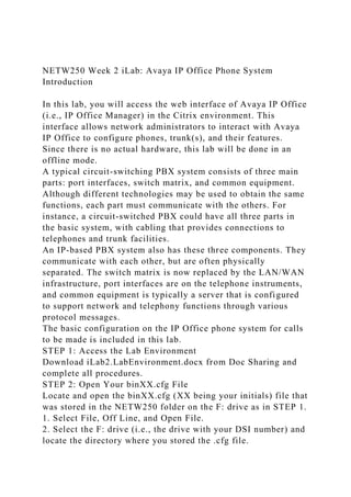
16. For this lab, let's assume that we have the network as shown
above.
From the topology, we must configure routing (or dial plan) for
four destinations: local phones, Telco VoIP trunk, Theirlab
VoIP PBX, and Thirdlab Analog PBX. In other words, we need
a routing table or matrix for different routes. What's typically
required in the table or matrix is listed below.
· Access Code: The first digit dialed to access a desired
destination.
· Destination: A label for the user to know where the facility
terminates.
· Direction: Specifies whether the facility is incoming,
outgoing, or 2-Way (both).
· Supervision: Specifies the supervision type used on the
circuit.
· Digits: Specifies the number of digits expected for access.
· Delete Digits: Specifies the number of leading digits that are
to be deleted from the dialed number.
· Prefix Digits: Specifies the number of leading digits that are
to be prefixed to the dialed number.
Now we know that we need to set up a matrix of 7 by 5
(horizontal by vertical, including header).
Access Code
Destination
Direction
Supervision
Signaling
Digits
Delete
Prefix
4
Local
2-Way
Loop
VoIP
17. 4
N
N
9
Telco
2-Way
VoIP
VoIP
7/11
N
N
5
Theirlab
2-Way
VoIP
VoIP
4
N
N
3
Thirdlab
2-Way
Ground Start
DTMF
4
1
N
Note that in the fourth case we need to dial four digits but only
transmit 3, thus one digit must be deleted. In our example, the
user would dial 33XX to dial another user at the Thirdlab
facility but only 3XX would be transmitted.
During this part of the lab, you will set up the routing
configuration described above.
1a. Enter Line Entry for TheirLab PBX
From the Configuration Tree panel, double-click Line to open
18. the IP Line window. You will need to create two line groups,
one for TheirLab PBX and the other for ThirdLab PBX (which
will be done later).
For this screen you need to enter 05 in Telephone Number to
match the first digit of TheirLab (i.e., Access Code). Also use
'00' for Line Number.
1b. Enter the TheirLab Gateway IP Address
In the same window, select the VoIP tab. On this screen you
only need to enter the Gateway IP Address.
For the TheirLab PBX connection, use the following data.
IP Address:
192.168.2.0
IP Mask:
255.255.255.0
Gateway IP Address:
192.168.2.1
Destination:
Select LAN1
Metric:
Leave Blank
ProxyARP:
Do not check.
2a. Enter Line Entry for ThirdLab PBX
Create another line entry for ThirdLab PBX, by right-clicking in
the empty space in the right window panel and selecting New.
For this screen you only need to enter 03 in Telephone Number
to match the first digit of ThirdLab (i.e., Access Code). Also
use '01' for Line Number.
19. 2b. Enter the ThirdLab Gateway IP Address
In the same window, select the VoIP tab. On this screen you
only need to enter the Gateway IP Address.
For the ThirdLab PBX connection that interfaces to a VoIP Mux
(built into the Avaya IP Office), use the following data.
IP Address:
192.168.1.0
IP Mask:
255.255.255.0
Gateway IP Address:
192.168.1.1
Destination:
Select LAN1
Metric:
Leave Blank
ProxyARP:
Do not check
3. Enter IP Route Data for TheirLab and ThirdLab
From the Configuration Tree panel, double-click IP Route to
open the IP Route window. You need to create two IP Routes—
one for TheirLab and another for ThirdLab.
For the TheirLab PBX connection, enter the following
information.
20. IP Address:
192.168.2.0
IP Mask:
255.255.255.0
Gateway IP Address:
192.168.2.1
Destination:
Select LAN1
Metric:
Leave Blank
ProxyARP:
Do not check.
For the ThirdLab PBX connection, enter the following
information.
IP Address:
192.168.1.0
IP Mask:
255.255.255.0
Gateway IP Address:
192.168.1.1
Destination:
Select LAN1
Metric:
Leave Blank
ProxyARP:
Do not check
4. Create Shortcode for TheirLab
From the Configuration Tree panel, double-click Shortcode to
open the Shortcode window (where appropriate Access Codes
for soft features have been entered in STEP 5).
Create a Shortcode screen for TheirLab by placing the cursor in
the right window panel, right-clicking the mouse, and selecting
New.
21. Enter 5XXX as the Short Code to access the TheirLab PBX and
enter 05 for the Line Group ID.
Select Dial from the Feature list. Enter enu in the Locale as the
designation code.
5. Create Shortcode for ThirdLab
Create a Shortcode screen for ThirdLab by placing the cursor in
the right window panel, right-clicking the mouse, and selecting
New.
Enter 33XX as the Short Code to access the ThirdLab PBX and
enter 03 for the Line Group ID.
Select Dial from the Feature list. Enter enu in the Locale as the
designation code.
6. Save Configuration Results
Save the configuration using Save As to the binXX.cfg (XX
being your initials) file on the Citrix F: drive.
Add to the iLab2.Report document the following screenshots.
· The IP Route tab on the Configuration Tree (i.e., the left panel
of the Configuration Tree window).
· Details of both IP Routes (i.e., the IP Route 192.168.1.0
window and the IP Route 192.168.2.0 window).
STEP 8: Submit Your Work
Save the most recent .cfg configuration file on your local drive
as explained in STEP 1.
Submit your zipped binXX.cfg configuration file and the Lab
Report document with all screenshots to the Dropbox for this
lab.
Page 26 of 26