Study on Air-Water & Water-Water Heat Exchange in a Finned Tube Exchanger
Voice Primer Lab.pdf
1. Developed for the Cisco Networking Academy Community by Dr. Ben Franske, Inver Hills Community College Page 1 of 5
CCNA Voice Primer Materials
Voice Primer Packet Tracer Lab
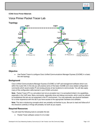
Topology
Objective
Use Packet Tracer to configure Cisco Unified Communications Manager Express (CUCME) in a basic
two site topology.
Background
Cisco Unified Communications Manager Express (CUCME) is VoIP call management software which runs
within the router IOS. In this lab you will practice some of the basic CUCME and voice related configuration
commands which would enable IP and analog phones at two locations to communicate. You will also apply
many of the configuration skills learned in your CCNA curriculum.
Note: Packet Tracer (PT) is a simulation tool not an emulation tool. It is somewhat limited in its capabilities,
especially in the VoIP area. Many commands, especially show and debug commands, which could be utilized
to troubleshoot this lab are not supported in the PT environment. You may optionally use physical hardware
for a richer experience with this lab if you have access to the appropriate hardware and software.
Note: This lab is introducing concepts which are probably not familiar to you. Be sure to read and follow all of
the directions carefully or things will probably not work as you expect.
Required Resources
You will need the following tools to complete this lab:
Packet Tracer software version 5.3.3 or later
Fa0/0
Fa0/1 Fa0/1
Fa0/0
Fa0/1
Fa0/1
Fa0/2 Fa0/3 Fa0/2
Fa0/3
Fa0/4
2. CCNA Voice Primer Materials
Developed for the Cisco Networking Academy Community by Dr. Ben Franske, Inver Hills Community College Page 2 of 5
IP Addressing Table
Device Interface Address
RouterA-1 FastEthernet0/0 n/a
FastEthernet0/0.10 172.16.10.1 /24
FastEthernet0/0.20 172.16.20.1 /24
FastEthernet0/0.99 172.16.99.1 /24
FastEthernet0/1 10.0.0.1/24
RouterB-1 FastEthernet0/0 n/a
FastEthernet0/0.10 172.17.10.1 /24
FastEthernet0/0.20 172.17.20.1 /24
FastEthernet0/0.99 172.17.99.1 /24
FastEthernet0/1 10.0.0.2/24
SwitchA-1 Vlan99 172.16.99.2
SwitchB-1 Vlan99 172.17.99.2
Step 1: Build the Packet Tracer Topology.
Open a new PT file and use the device and connections tools in PT to build the topology shown on the first
page of this lab. The IP phones at site A will be receiving Power over Ethernet (PoE) from the switch but the
IP phones at site B should be configured with power supplies.
Step 2: Perform basic device configuration.
On each router and switch:
Set the hostname as indicated on the topology diagram
Set the enable secret to class
Disable DNS lookups
Set a Telnet and Console password of cisco
Set IP addresses as indicated on the above chart
On each switch:
Create VLAN 10 with the name VOICE
Create VLAN 20 with the name DATA
Create VLAN 99 with the name MANAGEMENT
On each PC:
Configure to receive IP address via DHCP
Step 3: Configure DHCP service on the routers.
The VoIP devices and PCs in PT need to receive IP addressing information by DHCP. Each router will need
to act as the DHCP server for its location. We will be separating the voice and data networks at each location
so we will need two DHCP pools. The special DHCP option 150 is used to send the CUCME address to the
VoIP devices so they can register and receive configuration information. Even though this option is only
3. CCNA Voice Primer Materials
Developed for the Cisco Networking Academy Community by Dr. Ben Franske, Inver Hills Community College Page 3 of 5
required on the Voice VLAN we have included it on the Data VLAN in case soft-phones are ever used on the
PCs.
The commands to setup the DHCP pools on RouterA-1 are given below. You will have to modify them as
appropriate for RouterB-1 and apply them there as well.
RouterA-1(config)# ip dhcp pool VOICE
RouterA-1(dhcp-config)# network 172.16.10.0 255.255.255.0
RouterA-1(dhcp-config)# default-router 172.16.10.1
RouterA-1(dhcp-config)# option 150 ip 172.16.10.1
RouterA-1(config)# ip dhcp pool DATA
RouterA-1(dhcp-config)# network 172.16.20.0 255.255.255.0
RouterA-1(dhcp-config)# default-router 172.16.20.1
RouterA-1(dhcp-config)# option 150 ip 172.16.10.1
Step 4: Enable basic VoIP service on each router.
The DHCP option 150 instructs the VoIP devices receiving addresses to contact the router for registration and
configuration information. We must next configure the router to provide voice service to those devices.
Enable the VoIP service and set the maximum number of VoIP devices and directory numbers to 5 on each
router. We will also allow phones to self-register and get an extension number automatically from directory
numbers 1-5. Finally, the outgoing IP and port number for VoIP traffic from the router must be selected. The
example configuration commands for RouterA-1 are given below. Modify and apply to router B-1 as well.
RouterA-1(config)# telephony-service
RouterA-1(config-telephony)# max-ephones 5
RouterA-1(config-telephony)# max-dn 5
RouterA-1(config-telephony)# auto-reg-ephone
RouterA-1(config-telephony)# auto assign 1 to 5
RouterA-1(config-telephony)# ip source-address 172.16.10.1 port 2000
Step 5: Configure the pool of directory numbers on each router.
Each site will have a unique pool of directory (extension) numbers for each phone. On physical equipment it is
possible to have overlapping dial plans (the same extension numbers duplicated at both sites) and then use a
special prefix to dial between sites, but this is not supported by PT. We will need to ensure that each phone in
the topology has a unique number. The numbers at site A will all start with 4xxx and at site B they should all
start with 5xxx.
Below is the configuration for one of the directory numbers at site A. Create enough (correctly numbered)
directory numbers at each site to support all of the VoIP devices at that site.
RouterA-1(config)# ephone-dn 1
RouterA-1(config-ephone-dn)# number 4001
Step 6: Configure switch interfaces.
Trunk Ports:
Configure an 802.1Q trunk link from FastEthernet 0/1 on each switch to the router.
Access Ports:
All of the remaining ports on each switch should be configured as access ports in the DATA VLAN and
should have PortFast enabled. The ports should all be shutdown for security reasons unless they have a
device plugged into them. Enter this configuration as you normally would on the switches at both sites.
Remember that there are shortcuts to configuring multiple interfaces on a switch the same way.
4. CCNA Voice Primer Materials
Developed for the Cisco Networking Academy Community by Dr. Ben Franske, Inver Hills Community College Page 4 of 5
Because we want to have our IP phones on a different VLAN than our PCs we need to perform a special
configuration on all the access switch ports to turn them into two VLAN trunks when IP phones are
identified by CDP. Leave the ports in switchport mode access but add a special second VLAN to them
for voice traffic
SwitchA-1(config-if-range)# switchport voice vlan 10
At site A we also need to provide power to the IP phones using PoE:
SwitchA-1(config-if-range)# power inline auto
Step 7: Test the configuration.
At this point you should have enough configuration done for communications within each site to be working so
this is a good place to stop and test your work.
The first thing to check is to ensure all your devices have IP addresses in the appropriate subnets. Note that
after you enable all the ports it will take some time for all the devices to attempt requesting a DHCP address
again so if you don’t see addresses right away wait a couple minutes and check again. You can easily check
the addresses of IP phones and PCs by hovering your mouse over the device in PT and checking the listed IP
and gateway addresses. You can further check connectivity by pinging one of the interfaces on the router at
the same site from each PC.
Once your IP phones have IP addresses they should automatically contact the CUCME software running on
the router (using the option 150 address), register, and get an extension number. You can verify the extension
number of each IP phone by hovering your mouse over the phone and looking for a Line Number or by
opening the phone and checking on the upper right of the display on the GUI tab. Note that the Analog
Telephone Adapter (ATA) at site B does not use DHCP option 150 to find the CUCME server. You will have to
enter the correct server address on the Config tab of the ATA before the analog phone will receive an
extension number.
Once all your devices have extension numbers you can try placing a call between devices at the same site.
Click on one of the IP phones and switch to the GUI tab. Open up the same window for another IP phone at
the same site and place it next to the first window so you can see both phones at the same time. Enter the
extension number of the other phone on the dial pad of one phone and click on the receiver to place the call.
The other phone should indicate that it is ringing and the number of the extension which is calling should
appear on the display. Click the receiver on this phone to answer the call. The display should now show the
phones are Connected. If you look to the upper right of each phone (you may have to scroll over to the right)
you should see Do, Re, Mi buttons. Pressing one of these simulates talking into the phone. If you press one
you should see a message above the phone you are connected to like Playing ‘Do’… for a short while after
you press it. This indicates the connection between the phones is working properly.
Step 8: Configure site-to-site calling.
To enable site-to-site dialing we must make each of the two CUCME systems aware of the other so that they
can facilitate a connection between phones. Even though the CUCME systems manage the connection the
voice traffic is not required to flow through them (though it does in this topology when a call is being made
site-to-site). Because of this the first thing we need to do is make sure that every device at each site will be
able to reach all of the devices at the other site.
Add the appropriate routes to each router to enable routing between the sites. The most best way to do
this is with a single /16 summary route on each of the routers to manually summarize the addresses
found at the other site.
5. CCNA Voice Primer Materials
Developed for the Cisco Networking Academy Community by Dr. Ben Franske, Inver Hills Community College Page 5 of 5
Once you have the appropriate routes installed and have tested by successfully pinging from the PC at one
site to the PC at the other site we need to setup VoIP call routing between sites. This link is made by what is
called a dial-peer which identifies specific destination extensions and directs them to another CUCME server
in much the same way a routing table works for IP traffic. We must also identify what extension numbers to
direct to the other server, something done with a destination-pattern. Examine the dial-peer configuration
given for RouterA-1 below and then enter it into RouterA-1.
RouterA-1(config)# dial-peer voice 1 voip
RouterA-1(config-dial-peer)# destination-pattern 5...
RouterA-1(config-dial-peer)# session target ipv4:10.0.0.2
This will identify all extensions which start with a 5 followed by three other digits and direct them to the
CUCME server running on RouterB-1. Make the appropriate changes to this configuration and then apply it to
RouterB-1 to allow the VoIP devices at site B to call site A as well.
Test your configuration by calling from site A to site B and from site B to site A.
Challenge Lab Ideas:
If you want to challenge yourself try making some or all of these modifications to what you have done so far:
Add another VoIP device (IP phone or ATA) to site A
Setup specific devices to receive specific extension (directory) numbers. For example, make sure that
IP Phone A-1 always receives extension 4001 and IP ATA B-1 always receives extension 5003
instead of allowing devices to auto register. Hint: Exploring your running configurations on the routers
after you have everything working should provide some hints about how to do this.
Setup a multiuser Packet Tracer configuration and enable calling between your two sites and a
partner’s two sites
Add a third site and enable calling between all three sites
Add quality of service (QoS) to the network to prioritize voice traffic over data traffic
Lab Feedback:
This lab was developed as part of the Cisco Networking Academy Community VoIP initiative by Dr. Ben
Franske <b.franske@inverhills.edu> at Inver Hills Community College. Feedback is appreciated! If you have
difficulty understanding this lab, find an error or problem with the lab, or have a suggestion for improving it
please let us know.