Download to read offline


![Eliminating ‘false’ tripping cont..
4. Eliminating Rope expansion
• Reducing or eliminating rope expansion is an
obvious factor to look at
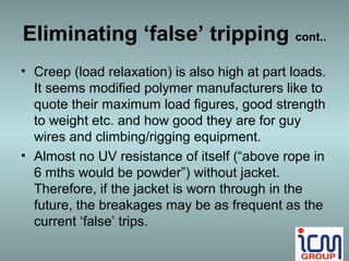
• Polymers, resins, kevlars etc have very low
expansion co-efficients (say less than 0.0001
compared to 0.013 for steel) but have high
elasticity and creep (stress relaxation) when
compared to steel.
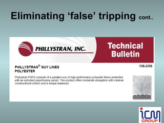
• Phillystran [modified polyester] quoted up to 7%
length variation at 10% of rated load. Their
10mm rope at 230n (AS pullout limit) would be
approx. 7% loaded.](https://image.slidesharecdn.com/ropeswitchreplacement-121211193012-phpapp01/85/Reliable-Rope-Switches-Presentation-12-320.jpg)
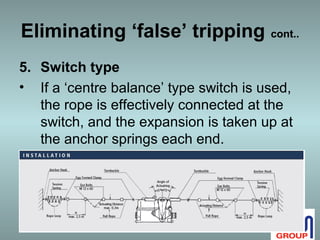
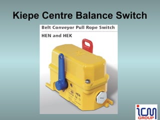
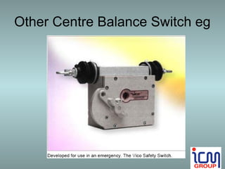


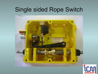
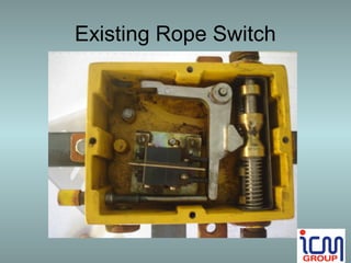
The document outlines a proposal for replacing existing rope switches at the Paraburdoo conveyor to eliminate nuisance trips and ensure compliance with safety standards. It details the impact of temperature on rope length and the challenges posed by current switch tolerances, while evaluating solutions such as switch type modification and materials with lower expansion coefficients. The proposed approach includes installing Kiepe centre balance switches and necessary components without causing downtime.


![Apos11 defining dt cut-offs using function [p p1-52 fri]](https://cdn.slidesharecdn.com/ss_thumbnails/apos11-definingdtcut-offsusingfunctionpp1-52fri-110207180353-phpapp01-thumbnail.jpg?width=640&height=640&fit=bounds)


