
Recommended
Recommended
More Related Content
What's hot
What's hot (20)
Similar to Hip Disarticulation Prosthetic Management
Similar to Hip Disarticulation Prosthetic Management (20)
Recently uploaded
Recently uploaded (20)
Hip Disarticulation Prosthetic Management
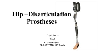
- 1. Hip –Disarticulation Prostheses Presenter :- RAVI PDUNIPPD (IPH) BPO (INTERN), 12th Batch
- 2. INTRODUCTION • Hip Disarticulation is the surgical removal of the entire lower limb by transection through the hip joint • Trying to overcome the loss of three weight – bearing joints, rather than one or two. • Not routinely seen in the average clinical practice. • Reduce mobility and increased energy expenditure during gait. • Prosthesis fitting is therefore limited to motivated and physiologically vigorous individuals and even then a significant number don’t become long term user.
- 3. CAUSES OF HIP DISARTICULATION AMPUTATION Hip disarticulation (Hd) accounts for only 2% of lower extremity amputation in the India and is mostly performed for; ( listed by number of occurrence) 1. Malignant musculoskeletal tumors ( most often in younger patients) 2. Limb ischemia ( perivascular diseases and complications to diabetes) 3. Trauma ( such severe traumas often result in the death of the patient) 4. Severe lower limbs infections ( chronic skin or bone infection) 5. Medical negligence
- 4. PROSTHETIC POINT OF VIEW Most Prosthetist have little experience with this type of amputation- only 20% of hip amputees use a prosthetic leg full-time (i.e. 8 to 12 hr./day) From these 20% only a small minority use a prosthetic leg without a cane or crutch This small minority of full time users without walking aids consists primarily of the young patients with malignant tumors. There is a persistent belief within the medical community that most middle aged hip- disarticulation amputees will ambulate with crutches or a wheelchair only!!!
- 5. Level of amputation in hip disarticulation Above the lesser trochanter True hip disarticulation hemipelvectomy
- 7. EVOLUTION OF HD PROSTHESES Tilting-table Prosthesis (1940) U.S. Navy Hydraulic Prosthesis(1945) Saucer-type Prosthesis(1957) Canadian Hip Disarticulation Prosthesis(1954)
- 8. UCLA Anatomical H.D. Prosthesis(1980) Dycor´s Roller Track Prosthetic Hip (1991) Ortho-system butterfly socket (1997) Silicone frame socket with Hipo-gross-Aqua hip joint (2000) EVOLUTION OF SOCKET TECHNOLOGY
- 9. Glenrose Semi-flexible Hip Disarticulation Socket (2005) Bikini Hip Socket technology (2013) Advances flex Hip Disarticulation Socket Design (2001)
- 11. PATIENT EVALUATION POINT MUST BE REMEMBERED :- a. balance, b. lower abdominal tissue condition, c. pelvic lordosis. a) BALANCE is needed to successfully put on and ambulate with the limb with minimal assistive aids. If this is not present, the client may not be considered a good prosthetic candidate. b) ABDOMINAL CONDITION must be evaluated for volume reduction and shaping to create a volumetrically tight and accurate anteroposterior (AP) fit between the sacrum and lower abdomen. The presence of any redundant or fleshy tissue should be noted because it must be contained and shaped to create reaction surfaces for proper prosthetic function. c) PELVIC LORDOSIS must also be evaluated because this is the main biomechanics work source during gait for maintaining knee stability and initiating knee flexion. To be successful in gait, the amputee should be able to demonstrate active pelvic lordosis using the muscles of the lower back and abdomen. The most successful amputees are able to maintain a low weight so that the maximum lordotic range of motion may be captured.
- 12. MEASUREMENTS • Tight mediolateral measurements are also necessary to preserve ML stability during gait. • ML measurements Over the iliac crests Between the trochanter and the iliac crests
- 13. LANDMARKS PRESSURE SENSITIVE • Pubis • iliac crests • costal margin • femoral head or joint PRESSURE TOLERANT • Gluteal tissues
- 14. CASTING TECHNIQUES There are two main methods of taking impressions:- 1. forming blocks 2. total suspension casting
- 15. FORMING BLOCKS STEPS INVOLVED :- i. The iliac crests, costal margin, pubis, femoral head or joint, and ischium are marked. ii. Plaster is wrapped over the lower limb from the perineum to 2 inches proximal to the iliac crests, and reinforcing splints are added to the ischial area. iii. The iliac crests are modified using plaster rope, surgical tubing, or radiator hose to forcefully compress the tissue circumferentially and downward. iv. In one method, the plaster rope is squeezed by being twisted around a dowel or hammer handle to attain good loading. The rope should be flattened in the sacral area to avoid localized pressure over the spinous processes. v. The patient is then seated on a flat surface and 45° forming blocks are placed anteriorly and posteriorly to create the AP reaction surfaces necessary for ambulation. vi. The posterior block is placed to load the gluteus and provide some relief for the ischium. vii. The anterior block is placed to help form the geometry for the hip attachment plate with 5° of external rotation. viii. The posterior forming block provides the counter pressure needed to maintain contact with the anterior block (Figure3). ix. Forming blocks work well for thinner clients with good muscle tone. x. For those who have soft abdominal tissue, the blocks may tend to distort the mold by expanding the ML.
- 16. Total Suspension Casting STEPS INVLVED i. The casting garment is suspended from the ceiling using a mechanical winch device. ii. When the support height has been adjusted to the point where the iliac crests are even, the same landmarks are indicated and the plaster splints are added. iii. The iliac crests are modified with the same roping technique, and the ischium is cupped in the palm of the hand (Figure 4). iv. The disadvantage of this technique is that the anterior surface is not clearly defined. v. Some Prosthetists use both casting methods by containing the tissue in suspension and then using forming blocks to place the hip joint.
- 17. AFTER CAST ( PREPRATIONS BEFORE MOLD) • Often the initial cast that is taken does not reduce the volume adequately to create a tight interface. • For this reason, the client should recline in the cast and the anterior panel should be cut. • The anterior section is squeezed together, lapping the anterior panels. • The location is marked and the cast is removed. • Before the mold is filled, the cast is again squeezed to this point and secured to eliminate extra interface volume and maintain circumferential tension.
- 18. MODIFICATION • After the cast is removed, the landmarks are remarked. • Plaster is removed from the anterior portion of the mold, avoiding the pubis. • When the abdomen is more pendulous, flattening is adequate; • thinner individuals may have a slight concavity to load the abdomen. • The posterior sacral area is also flattened along the lower back to maintain tight AP pressure. • To ensure a tight fit, one half inch of material should be removed between the trochanter and iliac crest to avoid the anterior superior iliac spine (ASIS) and the iliac crests from the measured ML. • The superior iliac crest modifications made with the plaster rope are then deepened by one quarter to one half inch even to the crests. • Some loading of the gluteus is also advisable to avoid too much ischial pressure. • SOME PROSTHETISTS have suggested that medial ischial pressure is advantageous but achieves little biomechanically without a distal reaction point. • Cupping of the ischium seems to be the most comfortable geometry. • Relief may have to be added to the pubis, iliac crests, and ASIS.
- 19. SOCKET DESIGN • The socket may be made with a side-opening or anterior- opening configuration, although the latter predominates because it is easier to put on and remove. • The trimlines are approximately 2 inches proximal to the iliac crests and through the perineum. A small suspension band is cut to provide relief on the contralateral ASIS.
- 30. COMPONENTS OF HIP – DISARTICULATION PROSTHESES 1) PROSTHETIC HIP JOINTS 2) PROSTHETIC KNEE JOINTS 3) PYLON 4) TUBE CLAMP ADAPTER 5) PROSTHETIC FEET
- 42. PYLON • Different pylons and attachment components are also available. • Twenty-two-mm Paediatric sizes are available along with the more common 30-mm pylon, and 34-mm pylons are available for heavier loads. • It is important to include an angled tube clamp above the knee to receive the upper femoral pylon, because this usually has a considerable anterior angle. • Carbon composite strut systems have been introduced that offer more dynamic motion and shock attenuation during stance. • The strut flexes when loaded and releases its force at the beginning of swing to increase hip and knee angular acceleration, which can help speed the step. • The disadvantage of this system is that the spring is lessened as the strut is shortened, and too soft a spring may dampen the initial anterior Lordotic movement.
- 48. MEDIO-LATERAL STABILITY To reduce undesirable perineal pressure, the canadian type socket is contoured to avoid excessive mediolateral motion. Throughout the stance phase of the prosthesis, the body’s center of gravity “W” exerts it’s downward force medial to the vertical support point “I”. The short distance between the line of gravity and the vertical support point minimizes the displacement. Sliding is reduced further by the diagonal forces exerted by the waistband over the sound hip as “H” and by the socket “S”.
- 49. Anterio-posterior stability At initial contact, as the prosthetic heel touches the ground, the GRF passes posterior to the ankle axis, the heel cushion compresses and the foot is lowered to the ground. At the same time an extension moment is created at the prosthetic knee as the GRF passes anterior to the prosthetic knee joint axis. By midstance, alignment stability is maximal as the GRF now passes posterior to the prosthetic hip joint axis and anterior to the prosthetic knee joint axis. As forward progression continues into pre-swing, the GRF moves posterior to the prosthetic knee axis, allowing the knee passively bend to facilitate swing phase foot clearance, while weight is being shifted onto the opposite limb.
- 50. ALIGNMENT • Stability of the hip disarticulation prosthesis relies primarily on the alignment of the prosthesis. IN THE BENCH ALIGNMENT :- A line is projected from the hip centre through the knee centre. • This line should fall 25 to 50 mm behind the heel of the shoe. • In the frontal plane, the hip joint should be placed 10 mm lateral to the frontal one-quarter mark with 5° to 10° of external rotation to match anatomic lower limb rotation. • The hip joint placement is established sagittally with the forming blocks. • The knee center and midfoot are placed in relationship to a plum line from the bisection of the interface based on their design. • For example, a single-axis knee is placed 15 mm posterior and a dynamic response midfoot is placed 20 mm anterior to the bisection. • The length of the prosthesis is 12 mm shorter than the sound side, so that the foot can clear the floor during midswing. • DURING DYNAMIC ALIGNMENT :- The hip joint should be adjusted so that it is not engaged before midstance during forward pelvic lordosis.
- 52. CHECKOUTS • The Prosthesis should be 1cm smaller in length than the normal leg • The line joining the HIP joint and BACK of the heel should paas 1cm anterior to the knee joint in full extension • Socket should provide Firm and Comfortable Support to ISCHIUM and in AP and ML directions in standing position. • The prosthesis should not drop away more than 2 cms. When amputee is asked to lift it from the floor. • In sitting a chair the pelvis should be level there should not be any discomfort or restriction. • In sitting the prosthetic thigh should not appear abnormally longer than the normal thigh.in sitting the sheen piece should be vertical. • After the walking is commenced knee stability after heel strike should be observed the heel of the foot should be soft otherwise it would be soft otherwise it would cause knee BUCKLING
- 53. TRAINING 1. STANDING AND WEIGHT TRANSFER FROM ONE FOOT TO ANOTHER 2. THE TRUNK SHOULD BE STRAIGHT THROUGH OUT THE GAIT. 3. TRUNK SHOULD NOT LEAN FORWARD WHILE WALKING.
- 54. THANK YOU