LoRaWAN Antenna Measurement
•
0 likes•77 views

LoRaWAN Antenna Measurement(SWR and Frequency Plot)

Recommended
Recommended
More Related Content
What's hot
What's hot (20)
Similar to LoRaWAN Antenna Measurement
Similar to LoRaWAN Antenna Measurement (20)
More from Radiojitter Concepts Lab LLP
Recently uploaded
Recently uploaded (20)
LoRaWAN Antenna Measurement
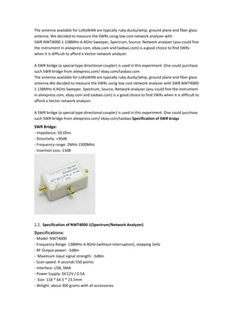
- 1. The antenna available for LoRaWAN are typically ruby ducky/whip, ground plane and fiber glass antenna. We decided to measure the SWRs using low cost network analyzer with SWR.NWT4000-1 138MHz-4.4GHz Sweeper, Spectrum, Source, Network analyzer (you could fine the instrument in aliexpress.com, ebay.com and taobao.com) is a good choice to find SWRs when it is difficult to afford a Vector network analyzer. A SWR bridge (a special type directional coupler) is used in this experiment. One could purchase such SWR bridge from aliexpress.com/ ebay.com/taobao.com. The antenna available for LoRaWAN are typically ruby ducky/whip, ground plane and fiber glass antenna.We decided to measure the SWRs using low cost network analyzer with SWR.NWT4000- 1 138MHz-4.4GHz Sweeper, Spectrum, Source, Network analyzer (you could fine the instrument in aliexpress.com, ebay.com and taobao.com) is a good choice to find SWRs when it is difficult to afford a Vector network analyzer. A SWR bridge (a special type directional coupler) is used in this experiment. One could purchase such SWR bridge from aliexpress.com/ ebay.com/taobao.Specification of SWR Bridge SWR Bridge: - Impedance: 50 Ohm - Directivity: >30dB - Frequency range: 2MHz-1500MHz - Insertion Loss: 13dB Specification of NWT4000-1(Spectrum/Network Analyzer) Specifications: - Model: NWT4000 - Frequency Range: 138MHz-4.4GHz (without interruption), stepping 1kHz - RF Output power: -5dBm - Maximum input signal strength: -5dBm - Scan speed: 4 seconds 550 points - Interface: USB, SMA - Power Supply: DC12V / 0.5A - Size: 118 * 64.5 * 23.5mm - Weight: about 300 grams with all accessories
- 2. NWT4000-1 connection to SWR Bridge The Output of NWT4000-1 is connected RF IN of SWR bridge, the input of NWT4000-1 is connected to RF OUT of the SWR bridge and DUT (Device under test) is connected to antenna connector. The spectrum analyzer software could be downloaded from http://www.dl4jal.eu/ OUT DUT Antenna IN NWT4000-1 Network Analyzer RF OUT RF IN SWR Bridge
- 3. Rubber ducky Antenna ,210 mm Lowest SWR 1.3 happens at 888 Mhz . At 868 MHz, SWR is around 1.98 Rubber ducky Antenna ,110 mm
- 4. Rubber ducky Antenna ,210 mm
- 5. Specification Electrical specifications Frequency Range(MHz) 868 Impedance(ohm) 50 Gain (dBi) 5.0 Polarization Vertical Radiation Omni VSWR <1.7 Maximum input power (W) 50 Mechanical specifications Connector SMA-Male Height 210mm Radome Material Polyurethane Color White Operating temperature (℃) -40~70
- 7. Ground Plane antenna Electrical specifications Frequency Range(MHz) 868 Polarization Vertical Gain (dBi) 3.0 Radiation Omni VSWR ≤1.5 Maximum input power (W) 50 Lighting Protection Direct Ground
- 8. Mechanical specifications Connector TNC (or according to customer) Dimension (mm) Ø115×225 mm Length of Cable(m) 3.0 Reflector material Stainless steel Operating temperature (℃) -50~70
- 9. Another DIY way to calculate SWR In this method, we used RTL SDR, Wide band Noise Generator and SWR Bridge. The signal is provider by wideband noise generator and return power is received by the RTL SDR. Equipment Noise Source/Tracking Generator 10-12V Power Supply RTL-SDR Dongle(From RTL-SDR Blog) SWR Bridge (20-23$) Directional Coupler 20dB or 10dB (3$) Software We used rtl_power with the RTL-SDR Panorama (http://sourceforge.net/projects/guiforrtlpower/ ) GUI to record and graph a frequency sweep over the effective range of the antenna. The SWR calculation is carried out by referring to excel sheet provided in https://www.rtl- sdr.com/rtl-sdr-tutorial-measuring-filter-characteristics-and-antenna-vswr-with-an-rtl-sdr-and-noise- source/ OUT DUT Antenna IN Noise Generator RF OUT RF IN SWR Bridge RTL Software Defined Radio
- 10. Scan the complete range without connecting the antenna and measure the return loss. Scan the complete range connecting the antenna and measure the return loss.
- 11. Directional Coupler as SWR Bridge Specification of Directional Coupler Specification Frequency Range (MHz) 698 - 2700 Coupling(db) 20 Insertion Loss(dB) ≤0.15 In-Band Ripple ≤0.3 VSWR ≤1.3 Impedance 50 Ohms IMD (dBc) ≤-140 @ +43dBm×2 Connectors N –Female Power Handling (Watts) 200 Peak Power(W) 1000 Temperature (℃) -35 to +70 Humidity 95% Environmental Specs indoor 0 1 2 3 4 5 6 750000000 800000000 850000000 900000000 950000000 1E+09 SWR Freq(Hz) SWR OUT Input Port Antenna IN Noise Generator Coupling Port Output Port Directional Coupler RTL Software Defined Radio
- 12. Directional Coupler Output Port: Noise Generator/Tracking Generator Directional Coupler Input Port: Antenna Directional Coupler Coupling Port: RTL SDR Receiver
- 13. 0 1 2 3 4 5 6 7 8 9 10 11 12 13 14 15 16 17 18 19 20 21 22 23 750000000 800000000 850000000 900000000 SWR Freq(Hz) SWR