SlideShare a Scribd company logo
1 of 7
Download to read offline
Cams
1. Introduction:-
A cam is a rotating machine element which gives reciprocating or
oscillating motion to another element known as follower. The cam rotates
usually at constant speed and drives the follower whose motion depends
upon the shape of the cam. Almost always the cam is the driver and the
follower is the driven.
In a cam mechanism, the three essential members are:
 The cam which has a curved surface or straight surface,
 The follower and
 The frame which supports and guides.
2-Types of Followers:
The followers which are having either reciprocating or oscillating motion,
are generally classified as:
 According to the surface in contact. The followers, according
to the surface in contact, are as follows :
 Knife edge follower: When the contacting end of the follower
has a sharp knife edge, it is called a knife edge follower, as
shown in Fig. (a).
 Roller follower: When the contacting end of the follower is a
roller, it is called a roller follower, as shown in Fig. (b).
 Flat faced or mushroom follower: When the contacting end of
the follower is a perfectly flat face, it is called a flat-faced
follower, as shown in Fig. (c).
 According to the motion of the follower:- The followers,
according to its motion, are of the following two types:
(a) Reciprocating or translating follower. When the follower
reciprocates in guides as the cam rotates uniformly, it is known as
reciprocating or translating follower. The followers as shown in
Fig. (a) to (c) are all reciprocating or translating followers.
(b) Oscillating or rotating follower. When the uniform rotary
motion of the cam is converted into predetermined oscillatory
motion of the follower, it is called oscillating or rotating follower.
The follower, as shown in Fig. below, is an oscillating or rotating
follower.
 According to the path of motion of the follower :- The followers,
according to its path of motion, are of the following two types:
 Radial follower. When the motion of the follower is along an axis
passing through the centre of the cam, it is known as radial
follower. The followers, as shown in Fig. (a) to (c), are all radial
followers.
 Off-set follower. When the motion of the follower is along an axis
away from the axis of the cam centre, it is called off-set follower.
The follower, as shown in Fig. below, is an off-set follower.
Note: Radial or disc cam. In radial cams, the follower reciprocates or
oscillates in a direction perpendicular to the cam axis.
3- Terms Used in Radial Cams:
Fig. below shows a radial cam with reciprocating roller follower. The
following terms are important in order to draw the cam profile.
1. Base circle. It is the smallest circle that can be drawn to the cam
profile.
2. Trace point. It is a reference point on the follower and is used to
generate the pitch curve. In case of knife edge follower, the knife edge
represents the trace point and the pitch curve corresponds to the cam
profile. In a roller follower, the centre of the roller represents the trace
point.
3. Pressure angle. It is the angle between the direction of the follower
motion and a normal to the pitch curve. This angle is very important in
designing a cam profile. If the pressure angle is too large, a reciprocating
follower will jam in its bearings.
4. Pitch point. It is a point on the pitch curve having the maximum
pressure angle.
5. Pitch circle. It is a circle drawn from the centre of the cam through the
pitch points.
6. Pitch curve. It is the curve generated by the trace point as the follower
moves relative to the cam. For a knife edge follower, the pitch curve and
the cam profile are same whereas for a roller follower, they are separated
by the radius of the roller.
7. Prime circle. It is the smallest circle that can be drawn from the centre
of the cam and tangent to the pitch curve. For a knife edge and a flat face
follower, the prime circle and the base circle are identical. For a roller
follower, the prime circle is larger than the base circle by the radius of the
roller.
8. Lift or stroke. It is the maximum travel of the follower from its lowest
position to the topmost position.
3- Motion of the Follower:-
The follower, during its travel, may have one of the following
motions.
1. Uniform motion or uniform velocity,
2. Simple harmonic motion.
3. Uniform acceleration and uniform retardation.
4. Cycloidal motion.
1- Displacement, Velocity and Acceleration Diagrams when
the Follower Moves with Uniform Velocity:-
The displacement, velocity and acceleration diagrams when a knife-
edged follower moves with uniform velocity are shown in Fig. (i) (a), (b)
and (c) respectively. The abscissa (base) represents the time (i.e. the
number of seconds required for the cam to complete one revolution) or it
may represent the angular displacement of the cam in degrees. The
ordinate represents the displacement, or velocity or acceleration of the
follower.
Since the follower moves with uniform velocity during its rise and
return stroke, therefore the slope of the displacement curves must be
constant. In other words, AB1 and C1D must be straight lines. A little
consideration will show that the follower remains at rest during part of
the cam rotation. The periods during which the follower remains at rest
are known as dwell periods, as shown by lines B1C1 and DE in Fig. (i)
(a). From Fig. (i) (c), we see that the acceleration or retardation of the
follower at the beginning and at the end of each stroke is infinite. This is
due to the fact that the follower is required to start from rest and has to
gain a velocity within no time. This is only possible if the acceleration or
retardation at the beginning and at the end of each stroke is infinite. These
conditions are however, impracticable.
(i) Displacement, velocity and
acceleration diagrams when the
follower moves with uniform velocity.
(ii) Modified displacement, velocity
and acceleration diagrams when the
follower moves with uniform velocity.
In order to have the acceleration and retardation within the finite
limits, it is necessary to modify the conditions which govern the motion
of the follower. This may be done by rounding off the sharp corners of
the displacement diagram at the beginning and at the end of each stroke,
as shown in Fig. (ii) (a). By doing so, the velocity of the follower
increases gradually to its maximum value at the beginning of each stroke
and decreases gradually to zero at the end of each stroke as shown in Fig.
(ii) (b). The modified displacement, velocity and acceleration diagrams
are shown in Fig. (ii). The round corners of the displacement diagram are
usually parabolic curves because the parabolic motion results in a very
low acceleration of the follower for a given stroke and cam speed.
Example(1):- A cam is to give the following motion to a knife-edged
follower : 1. Outstroke during 60° of cam rotation ; 2. Dwell for the next
30° of cam rotation ; 3. Return stroke during next 60° of cam rotation,
and 4. Dwell for the remaining 210° of cam rotation.
The stroke of the follower is 40 mm and the minimum radius of the
cam is 50 mm. The follower moves with uniform velocity during both the
outstroke and return strokes. Draw the profile of the cam when (a) the
axis of the follower passes through the axis of the cam shaft, and
(b) the axis of the follower is offset by 20 mm from the axis of the cam
shaft.
4 12875 515

More Related Content

What's hot

What's hot (19)

Classification of Followers
Classification of FollowersClassification of Followers
Classification of Followers
 
Sai Cam
Sai CamSai Cam
Sai Cam
 
Chapter 5 cam mechanisms
Chapter 5 cam mechanismsChapter 5 cam mechanisms
Chapter 5 cam mechanisms
 
Cams and Followers
Cams and Followers Cams and Followers
Cams and Followers
 
Cams and Followers
Cams and FollowersCams and Followers
Cams and Followers
 
Construction of Cam
Construction of CamConstruction of Cam
Construction of Cam
 
Cam mech
Cam mechCam mech
Cam mech
 
Cam profile
Cam profileCam profile
Cam profile
 
Cam displacement diagram 002
Cam displacement diagram 002Cam displacement diagram 002
Cam displacement diagram 002
 
Cam displacement diagram
Cam displacement diagramCam displacement diagram
Cam displacement diagram
 
Kinematics of cam mechanisms
Kinematics of cam mechanismsKinematics of cam mechanisms
Kinematics of cam mechanisms
 
Cam & Profile
Cam & Profile Cam & Profile
Cam & Profile
 
Met 305 tutorial_6_cams
Met 305 tutorial_6_camsMet 305 tutorial_6_cams
Met 305 tutorial_6_cams
 
cam design
cam designcam design
cam design
 
Kinematics of Cams and Follower
Kinematics of Cams and FollowerKinematics of Cams and Follower
Kinematics of Cams and Follower
 
Types of cams and follower
Types of cams and followerTypes of cams and follower
Types of cams and follower
 
A project report on cam follower utility in internal combustion engine
A project report on cam follower utility in internal combustion engineA project report on cam follower utility in internal combustion engine
A project report on cam follower utility in internal combustion engine
 
Cams
CamsCams
Cams
 
Chapter 8
Chapter 8Chapter 8
Chapter 8
 

Similar to 4 12875 515

camsfollowers-190301142036.pdf
camsfollowers-190301142036.pdfcamsfollowers-190301142036.pdf
camsfollowers-190301142036.pdfAhmed Sobhi
 
Cams & followers
Cams & followersCams & followers
Cams & followersTechHelp3
 
CAM&FOLLOWER.ppt
CAM&FOLLOWER.pptCAM&FOLLOWER.ppt
CAM&FOLLOWER.pptPopatRavi1
 
CAM AND FOLLOWER
CAM AND FOLLOWERCAM AND FOLLOWER
CAM AND FOLLOWERAJAY SAVITA
 
UNIT-III CAM and Follower mechanics of machine
UNIT-III CAM and Follower mechanics of machineUNIT-III CAM and Follower mechanics of machine
UNIT-III CAM and Follower mechanics of machinesamy709581
 
ch3 cams and follower.pdf
ch3 cams and follower.pdfch3 cams and follower.pdf
ch3 cams and follower.pdfEliasLibay
 
Cam and follower
Cam and followerCam and follower
Cam and followerR A Shah
 
CAM Mechanism Reading Material.pdf
CAM Mechanism Reading Material.pdfCAM Mechanism Reading Material.pdf
CAM Mechanism Reading Material.pdfSandip Paudel
 
ANANTA CAM FOLLOWER PPTX.pptxmechanical engineering
ANANTA CAM FOLLOWER PPTX.pptxmechanical engineeringANANTA CAM FOLLOWER PPTX.pptxmechanical engineering
ANANTA CAM FOLLOWER PPTX.pptxmechanical engineeringAnantaKumarNandi
 
CAM introductions
CAM introductions CAM introductions
CAM introductions skvskv87
 
3131906 -CAMS- KINETICS AND DYNAMICS OF MACHINE
3131906 -CAMS- KINETICS AND DYNAMICS OF MACHINE3131906 -CAMS- KINETICS AND DYNAMICS OF MACHINE
3131906 -CAMS- KINETICS AND DYNAMICS OF MACHINETakshil Gajjar
 
typesofcamsandfollower-151108043025-lva1-app6892 (1).pdf
typesofcamsandfollower-151108043025-lva1-app6892 (1).pdftypesofcamsandfollower-151108043025-lva1-app6892 (1).pdf
typesofcamsandfollower-151108043025-lva1-app6892 (1).pdfKunjDhoot
 
UNIT -3 -KINEMATICS OF CAM MECHANISMS.ppt
UNIT -3 -KINEMATICS OF CAM MECHANISMS.pptUNIT -3 -KINEMATICS OF CAM MECHANISMS.ppt
UNIT -3 -KINEMATICS OF CAM MECHANISMS.pptkarthi keyan
 
KOM - Unit 3 -kinematics of cam mechanisms
KOM - Unit  3 -kinematics of cam mechanismsKOM - Unit  3 -kinematics of cam mechanisms
KOM - Unit 3 -kinematics of cam mechanismskarthi keyan
 

Similar to 4 12875 515 (20)

camsfollowers-190301142036.pdf
camsfollowers-190301142036.pdfcamsfollowers-190301142036.pdf
camsfollowers-190301142036.pdf
 
Cams & followers
Cams & followersCams & followers
Cams & followers
 
CAM&FOLLOWER.ppt
CAM&FOLLOWER.pptCAM&FOLLOWER.ppt
CAM&FOLLOWER.ppt
 
CAM AND FOLLOWER
CAM AND FOLLOWERCAM AND FOLLOWER
CAM AND FOLLOWER
 
UNIT-III CAM and Follower mechanics of machine
UNIT-III CAM and Follower mechanics of machineUNIT-III CAM and Follower mechanics of machine
UNIT-III CAM and Follower mechanics of machine
 
CAM
CAMCAM
CAM
 
ch3 cams and follower.pdf
ch3 cams and follower.pdfch3 cams and follower.pdf
ch3 cams and follower.pdf
 
Function of cam.pptx
Function of cam.pptxFunction of cam.pptx
Function of cam.pptx
 
Cams
CamsCams
Cams
 
cams
camscams
cams
 
Cam and follower
Cam and followerCam and follower
Cam and follower
 
CAM Mechanism Reading Material.pdf
CAM Mechanism Reading Material.pdfCAM Mechanism Reading Material.pdf
CAM Mechanism Reading Material.pdf
 
ME 6401-Unit-3.pptx
ME 6401-Unit-3.pptxME 6401-Unit-3.pptx
ME 6401-Unit-3.pptx
 
ANANTA CAM FOLLOWER PPTX.pptxmechanical engineering
ANANTA CAM FOLLOWER PPTX.pptxmechanical engineeringANANTA CAM FOLLOWER PPTX.pptxmechanical engineering
ANANTA CAM FOLLOWER PPTX.pptxmechanical engineering
 
CAM introductions
CAM introductions CAM introductions
CAM introductions
 
CAM and FOLLOWER.pdf
CAM and FOLLOWER.pdfCAM and FOLLOWER.pdf
CAM and FOLLOWER.pdf
 
3131906 -CAMS- KINETICS AND DYNAMICS OF MACHINE
3131906 -CAMS- KINETICS AND DYNAMICS OF MACHINE3131906 -CAMS- KINETICS AND DYNAMICS OF MACHINE
3131906 -CAMS- KINETICS AND DYNAMICS OF MACHINE
 
typesofcamsandfollower-151108043025-lva1-app6892 (1).pdf
typesofcamsandfollower-151108043025-lva1-app6892 (1).pdftypesofcamsandfollower-151108043025-lva1-app6892 (1).pdf
typesofcamsandfollower-151108043025-lva1-app6892 (1).pdf
 
UNIT -3 -KINEMATICS OF CAM MECHANISMS.ppt
UNIT -3 -KINEMATICS OF CAM MECHANISMS.pptUNIT -3 -KINEMATICS OF CAM MECHANISMS.ppt
UNIT -3 -KINEMATICS OF CAM MECHANISMS.ppt
 
KOM - Unit 3 -kinematics of cam mechanisms
KOM - Unit  3 -kinematics of cam mechanismsKOM - Unit  3 -kinematics of cam mechanisms
KOM - Unit 3 -kinematics of cam mechanisms
 

Recently uploaded

ZXCTN 5804 / ZTE PTN / ZTE POTN / ZTE 5804 PTN / ZTE POTN 5804 ( 100/200 GE Z...
ZXCTN 5804 / ZTE PTN / ZTE POTN / ZTE 5804 PTN / ZTE POTN 5804 ( 100/200 GE Z...ZXCTN 5804 / ZTE PTN / ZTE POTN / ZTE 5804 PTN / ZTE POTN 5804 ( 100/200 GE Z...
ZXCTN 5804 / ZTE PTN / ZTE POTN / ZTE 5804 PTN / ZTE POTN 5804 ( 100/200 GE Z...ZTE
 
CCS355 Neural Network & Deep Learning Unit II Notes with Question bank .pdf
CCS355 Neural Network & Deep Learning Unit II Notes with Question bank .pdfCCS355 Neural Network & Deep Learning Unit II Notes with Question bank .pdf
CCS355 Neural Network & Deep Learning Unit II Notes with Question bank .pdfAsst.prof M.Gokilavani
 
Software and Systems Engineering Standards: Verification and Validation of Sy...
Software and Systems Engineering Standards: Verification and Validation of Sy...Software and Systems Engineering Standards: Verification and Validation of Sy...
Software and Systems Engineering Standards: Verification and Validation of Sy...VICTOR MAESTRE RAMIREZ
 
chaitra-1.pptx fake news detection using machine learning
chaitra-1.pptx  fake news detection using machine learningchaitra-1.pptx  fake news detection using machine learning
chaitra-1.pptx fake news detection using machine learningmisbanausheenparvam
 
College Call Girls Nashik Nehal 7001305949 Independent Escort Service Nashik
College Call Girls Nashik Nehal 7001305949 Independent Escort Service NashikCollege Call Girls Nashik Nehal 7001305949 Independent Escort Service Nashik
College Call Girls Nashik Nehal 7001305949 Independent Escort Service NashikCall Girls in Nagpur High Profile
 
Decoding Kotlin - Your guide to solving the mysterious in Kotlin.pptx
Decoding Kotlin - Your guide to solving the mysterious in Kotlin.pptxDecoding Kotlin - Your guide to solving the mysterious in Kotlin.pptx
Decoding Kotlin - Your guide to solving the mysterious in Kotlin.pptxJoão Esperancinha
 
Microscopic Analysis of Ceramic Materials.pptx
Microscopic Analysis of Ceramic Materials.pptxMicroscopic Analysis of Ceramic Materials.pptx
Microscopic Analysis of Ceramic Materials.pptxpurnimasatapathy1234
 
Model Call Girl in Narela Delhi reach out to us at 🔝8264348440🔝
Model Call Girl in Narela Delhi reach out to us at 🔝8264348440🔝Model Call Girl in Narela Delhi reach out to us at 🔝8264348440🔝
Model Call Girl in Narela Delhi reach out to us at 🔝8264348440🔝soniya singh
 
Artificial-Intelligence-in-Electronics (K).pptx
Artificial-Intelligence-in-Electronics (K).pptxArtificial-Intelligence-in-Electronics (K).pptx
Artificial-Intelligence-in-Electronics (K).pptxbritheesh05
 
power system scada applications and uses
power system scada applications and usespower system scada applications and uses
power system scada applications and usesDevarapalliHaritha
 
What are the advantages and disadvantages of membrane structures.pptx
What are the advantages and disadvantages of membrane structures.pptxWhat are the advantages and disadvantages of membrane structures.pptx
What are the advantages and disadvantages of membrane structures.pptxwendy cai
 
microprocessor 8085 and its interfacing
microprocessor 8085  and its interfacingmicroprocessor 8085  and its interfacing
microprocessor 8085 and its interfacingjaychoudhary37
 
Architect Hassan Khalil Portfolio for 2024
Architect Hassan Khalil Portfolio for 2024Architect Hassan Khalil Portfolio for 2024
Architect Hassan Khalil Portfolio for 2024hassan khalil
 
Gfe Mayur Vihar Call Girls Service WhatsApp -> 9999965857 Available 24x7 ^ De...
Gfe Mayur Vihar Call Girls Service WhatsApp -> 9999965857 Available 24x7 ^ De...Gfe Mayur Vihar Call Girls Service WhatsApp -> 9999965857 Available 24x7 ^ De...
Gfe Mayur Vihar Call Girls Service WhatsApp -> 9999965857 Available 24x7 ^ De...srsj9000
 
Introduction to Microprocesso programming and interfacing.pptx
Introduction to Microprocesso programming and interfacing.pptxIntroduction to Microprocesso programming and interfacing.pptx
Introduction to Microprocesso programming and interfacing.pptxvipinkmenon1
 
Biology for Computer Engineers Course Handout.pptx
Biology for Computer Engineers Course Handout.pptxBiology for Computer Engineers Course Handout.pptx
Biology for Computer Engineers Course Handout.pptxDeepakSakkari2
 
Gurgaon ✡️9711147426✨Call In girls Gurgaon Sector 51 escort service
Gurgaon ✡️9711147426✨Call In girls Gurgaon Sector 51 escort serviceGurgaon ✡️9711147426✨Call In girls Gurgaon Sector 51 escort service
Gurgaon ✡️9711147426✨Call In girls Gurgaon Sector 51 escort servicejennyeacort
 
High Profile Call Girls Nagpur Isha Call 7001035870 Meet With Nagpur Escorts
High Profile Call Girls Nagpur Isha Call 7001035870 Meet With Nagpur EscortsHigh Profile Call Girls Nagpur Isha Call 7001035870 Meet With Nagpur Escorts
High Profile Call Girls Nagpur Isha Call 7001035870 Meet With Nagpur Escortsranjana rawat
 

Recently uploaded (20)

ZXCTN 5804 / ZTE PTN / ZTE POTN / ZTE 5804 PTN / ZTE POTN 5804 ( 100/200 GE Z...
ZXCTN 5804 / ZTE PTN / ZTE POTN / ZTE 5804 PTN / ZTE POTN 5804 ( 100/200 GE Z...ZXCTN 5804 / ZTE PTN / ZTE POTN / ZTE 5804 PTN / ZTE POTN 5804 ( 100/200 GE Z...
ZXCTN 5804 / ZTE PTN / ZTE POTN / ZTE 5804 PTN / ZTE POTN 5804 ( 100/200 GE Z...
 
CCS355 Neural Network & Deep Learning Unit II Notes with Question bank .pdf
CCS355 Neural Network & Deep Learning Unit II Notes with Question bank .pdfCCS355 Neural Network & Deep Learning Unit II Notes with Question bank .pdf
CCS355 Neural Network & Deep Learning Unit II Notes with Question bank .pdf
 
Software and Systems Engineering Standards: Verification and Validation of Sy...
Software and Systems Engineering Standards: Verification and Validation of Sy...Software and Systems Engineering Standards: Verification and Validation of Sy...
Software and Systems Engineering Standards: Verification and Validation of Sy...
 
chaitra-1.pptx fake news detection using machine learning
chaitra-1.pptx  fake news detection using machine learningchaitra-1.pptx  fake news detection using machine learning
chaitra-1.pptx fake news detection using machine learning
 
9953056974 Call Girls In South Ex, Escorts (Delhi) NCR.pdf
9953056974 Call Girls In South Ex, Escorts (Delhi) NCR.pdf9953056974 Call Girls In South Ex, Escorts (Delhi) NCR.pdf
9953056974 Call Girls In South Ex, Escorts (Delhi) NCR.pdf
 
College Call Girls Nashik Nehal 7001305949 Independent Escort Service Nashik
College Call Girls Nashik Nehal 7001305949 Independent Escort Service NashikCollege Call Girls Nashik Nehal 7001305949 Independent Escort Service Nashik
College Call Girls Nashik Nehal 7001305949 Independent Escort Service Nashik
 
Decoding Kotlin - Your guide to solving the mysterious in Kotlin.pptx
Decoding Kotlin - Your guide to solving the mysterious in Kotlin.pptxDecoding Kotlin - Your guide to solving the mysterious in Kotlin.pptx
Decoding Kotlin - Your guide to solving the mysterious in Kotlin.pptx
 
Microscopic Analysis of Ceramic Materials.pptx
Microscopic Analysis of Ceramic Materials.pptxMicroscopic Analysis of Ceramic Materials.pptx
Microscopic Analysis of Ceramic Materials.pptx
 
Exploring_Network_Security_with_JA3_by_Rakesh Seal.pptx
Exploring_Network_Security_with_JA3_by_Rakesh Seal.pptxExploring_Network_Security_with_JA3_by_Rakesh Seal.pptx
Exploring_Network_Security_with_JA3_by_Rakesh Seal.pptx
 
Model Call Girl in Narela Delhi reach out to us at 🔝8264348440🔝
Model Call Girl in Narela Delhi reach out to us at 🔝8264348440🔝Model Call Girl in Narela Delhi reach out to us at 🔝8264348440🔝
Model Call Girl in Narela Delhi reach out to us at 🔝8264348440🔝
 
Artificial-Intelligence-in-Electronics (K).pptx
Artificial-Intelligence-in-Electronics (K).pptxArtificial-Intelligence-in-Electronics (K).pptx
Artificial-Intelligence-in-Electronics (K).pptx
 
power system scada applications and uses
power system scada applications and usespower system scada applications and uses
power system scada applications and uses
 
What are the advantages and disadvantages of membrane structures.pptx
What are the advantages and disadvantages of membrane structures.pptxWhat are the advantages and disadvantages of membrane structures.pptx
What are the advantages and disadvantages of membrane structures.pptx
 
microprocessor 8085 and its interfacing
microprocessor 8085  and its interfacingmicroprocessor 8085  and its interfacing
microprocessor 8085 and its interfacing
 
Architect Hassan Khalil Portfolio for 2024
Architect Hassan Khalil Portfolio for 2024Architect Hassan Khalil Portfolio for 2024
Architect Hassan Khalil Portfolio for 2024
 
Gfe Mayur Vihar Call Girls Service WhatsApp -> 9999965857 Available 24x7 ^ De...
Gfe Mayur Vihar Call Girls Service WhatsApp -> 9999965857 Available 24x7 ^ De...Gfe Mayur Vihar Call Girls Service WhatsApp -> 9999965857 Available 24x7 ^ De...
Gfe Mayur Vihar Call Girls Service WhatsApp -> 9999965857 Available 24x7 ^ De...
 
Introduction to Microprocesso programming and interfacing.pptx
Introduction to Microprocesso programming and interfacing.pptxIntroduction to Microprocesso programming and interfacing.pptx
Introduction to Microprocesso programming and interfacing.pptx
 
Biology for Computer Engineers Course Handout.pptx
Biology for Computer Engineers Course Handout.pptxBiology for Computer Engineers Course Handout.pptx
Biology for Computer Engineers Course Handout.pptx
 
Gurgaon ✡️9711147426✨Call In girls Gurgaon Sector 51 escort service
Gurgaon ✡️9711147426✨Call In girls Gurgaon Sector 51 escort serviceGurgaon ✡️9711147426✨Call In girls Gurgaon Sector 51 escort service
Gurgaon ✡️9711147426✨Call In girls Gurgaon Sector 51 escort service
 
High Profile Call Girls Nagpur Isha Call 7001035870 Meet With Nagpur Escorts
High Profile Call Girls Nagpur Isha Call 7001035870 Meet With Nagpur EscortsHigh Profile Call Girls Nagpur Isha Call 7001035870 Meet With Nagpur Escorts
High Profile Call Girls Nagpur Isha Call 7001035870 Meet With Nagpur Escorts
 

4 12875 515

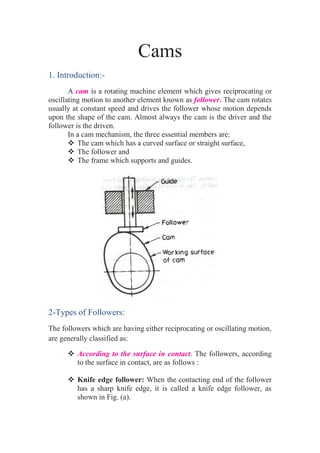
  • 1. Cams 1. Introduction:- A cam is a rotating machine element which gives reciprocating or oscillating motion to another element known as follower. The cam rotates usually at constant speed and drives the follower whose motion depends upon the shape of the cam. Almost always the cam is the driver and the follower is the driven. In a cam mechanism, the three essential members are:  The cam which has a curved surface or straight surface,  The follower and  The frame which supports and guides. 2-Types of Followers: The followers which are having either reciprocating or oscillating motion, are generally classified as:  According to the surface in contact. The followers, according to the surface in contact, are as follows :  Knife edge follower: When the contacting end of the follower has a sharp knife edge, it is called a knife edge follower, as shown in Fig. (a).
  • 2.  Roller follower: When the contacting end of the follower is a roller, it is called a roller follower, as shown in Fig. (b).  Flat faced or mushroom follower: When the contacting end of the follower is a perfectly flat face, it is called a flat-faced follower, as shown in Fig. (c).  According to the motion of the follower:- The followers, according to its motion, are of the following two types: (a) Reciprocating or translating follower. When the follower reciprocates in guides as the cam rotates uniformly, it is known as reciprocating or translating follower. The followers as shown in Fig. (a) to (c) are all reciprocating or translating followers. (b) Oscillating or rotating follower. When the uniform rotary motion of the cam is converted into predetermined oscillatory motion of the follower, it is called oscillating or rotating follower. The follower, as shown in Fig. below, is an oscillating or rotating follower.
  • 3.  According to the path of motion of the follower :- The followers, according to its path of motion, are of the following two types:  Radial follower. When the motion of the follower is along an axis passing through the centre of the cam, it is known as radial follower. The followers, as shown in Fig. (a) to (c), are all radial followers.  Off-set follower. When the motion of the follower is along an axis away from the axis of the cam centre, it is called off-set follower. The follower, as shown in Fig. below, is an off-set follower. Note: Radial or disc cam. In radial cams, the follower reciprocates or oscillates in a direction perpendicular to the cam axis. 3- Terms Used in Radial Cams: Fig. below shows a radial cam with reciprocating roller follower. The following terms are important in order to draw the cam profile. 1. Base circle. It is the smallest circle that can be drawn to the cam profile. 2. Trace point. It is a reference point on the follower and is used to generate the pitch curve. In case of knife edge follower, the knife edge represents the trace point and the pitch curve corresponds to the cam profile. In a roller follower, the centre of the roller represents the trace point. 3. Pressure angle. It is the angle between the direction of the follower motion and a normal to the pitch curve. This angle is very important in designing a cam profile. If the pressure angle is too large, a reciprocating follower will jam in its bearings.
  • 4. 4. Pitch point. It is a point on the pitch curve having the maximum pressure angle. 5. Pitch circle. It is a circle drawn from the centre of the cam through the pitch points. 6. Pitch curve. It is the curve generated by the trace point as the follower moves relative to the cam. For a knife edge follower, the pitch curve and the cam profile are same whereas for a roller follower, they are separated by the radius of the roller. 7. Prime circle. It is the smallest circle that can be drawn from the centre of the cam and tangent to the pitch curve. For a knife edge and a flat face follower, the prime circle and the base circle are identical. For a roller follower, the prime circle is larger than the base circle by the radius of the roller. 8. Lift or stroke. It is the maximum travel of the follower from its lowest position to the topmost position. 3- Motion of the Follower:- The follower, during its travel, may have one of the following motions. 1. Uniform motion or uniform velocity, 2. Simple harmonic motion. 3. Uniform acceleration and uniform retardation. 4. Cycloidal motion.
  • 5. 1- Displacement, Velocity and Acceleration Diagrams when the Follower Moves with Uniform Velocity:- The displacement, velocity and acceleration diagrams when a knife- edged follower moves with uniform velocity are shown in Fig. (i) (a), (b) and (c) respectively. The abscissa (base) represents the time (i.e. the number of seconds required for the cam to complete one revolution) or it may represent the angular displacement of the cam in degrees. The ordinate represents the displacement, or velocity or acceleration of the follower. Since the follower moves with uniform velocity during its rise and return stroke, therefore the slope of the displacement curves must be constant. In other words, AB1 and C1D must be straight lines. A little consideration will show that the follower remains at rest during part of the cam rotation. The periods during which the follower remains at rest are known as dwell periods, as shown by lines B1C1 and DE in Fig. (i) (a). From Fig. (i) (c), we see that the acceleration or retardation of the follower at the beginning and at the end of each stroke is infinite. This is due to the fact that the follower is required to start from rest and has to gain a velocity within no time. This is only possible if the acceleration or retardation at the beginning and at the end of each stroke is infinite. These conditions are however, impracticable. (i) Displacement, velocity and acceleration diagrams when the follower moves with uniform velocity. (ii) Modified displacement, velocity and acceleration diagrams when the follower moves with uniform velocity.
  • 6. In order to have the acceleration and retardation within the finite limits, it is necessary to modify the conditions which govern the motion of the follower. This may be done by rounding off the sharp corners of the displacement diagram at the beginning and at the end of each stroke, as shown in Fig. (ii) (a). By doing so, the velocity of the follower increases gradually to its maximum value at the beginning of each stroke and decreases gradually to zero at the end of each stroke as shown in Fig. (ii) (b). The modified displacement, velocity and acceleration diagrams are shown in Fig. (ii). The round corners of the displacement diagram are usually parabolic curves because the parabolic motion results in a very low acceleration of the follower for a given stroke and cam speed. Example(1):- A cam is to give the following motion to a knife-edged follower : 1. Outstroke during 60° of cam rotation ; 2. Dwell for the next 30° of cam rotation ; 3. Return stroke during next 60° of cam rotation, and 4. Dwell for the remaining 210° of cam rotation. The stroke of the follower is 40 mm and the minimum radius of the cam is 50 mm. The follower moves with uniform velocity during both the outstroke and return strokes. Draw the profile of the cam when (a) the axis of the follower passes through the axis of the cam shaft, and (b) the axis of the follower is offset by 20 mm from the axis of the cam shaft.