![University Institute of Engineering (UIE)
Department of Computer Science and Engineering (CSE)
Contents of the Syllabus
3
UNIT-I [10h]
Overview of Databases: Database concepts, DBMS, Data Base System Architecture (Three
Level ANSI-SPARC Architecture), Advantages and Disadvantages of DBMS, Data Independence, DBA
and Responsibilities of DBA, Relational Data Structure, Keys, Relations, Attributes, Schema and
Instances, Referential integrity, Entity integrity.
Data Models: Relational Model, Network Model, Hierarchical Model, ER Model: Design,
issues, Mapping constraints, ER diagram, Comparison of Models.
Relational Algebra & Relational Calculus: Introduction, Syntax, Semantics, Additional
operators, Grouping and Ungrouping, Relational comparisons, Tuple Calculus, Domain Calculus,
Calculus Vs Algebra, Computational capabilities.
UNIT-II [10h]
Functional dependencies and Normalization: Functional dependencies, Decomposition, Full
Functional Dependency (FFD), Transitive Dependency (TD), Join Dependency (JD), Multi-valued
Dependency (MVD), Normal Forms (1NF, 2NF, 3NF, BCNF), De-normalization.
Database Security: Introduction, Threats, Counter Measures.
Control Structures: Introduction to conditional control, Iterative control and sequential control
statements, Cursors, Views.](data:image/gif;base64,R0lGODlhAQABAIAAAAAAAP///yH5BAEAAAAALAAAAAABAAEAAAIBRAA7)
Recommended
More Related Content
Similar to PPT Lecture 2.1 and 2.2 DataModels.ppt
Similar to PPT Lecture 2.1 and 2.2 DataModels.ppt (20)
Recently uploaded
Recently uploaded (20)
PPT Lecture 2.1 and 2.2 DataModels.ppt
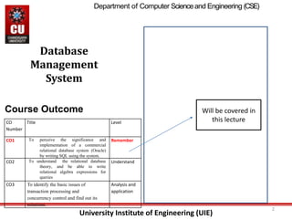
- 1. University Institute of Engineering (UIE) 2 Database Management System CO Number Title Level CO1 To perceive the significance and implementation of a commercial relational database system (Oracle) by writing SQL using the system. Remember CO2 To understand the relational database theory, and be able to write relational algebra expressions for queries Understand CO3 To identify the basic issues of transaction processing and concurrency control and find out its solutions. Analysis and application Course Outcome Will be covered in this lecture Department of Computer Scienceand Engineering (CSE)
- 2. University Institute of Engineering (UIE) Department of Computer Science and Engineering (CSE) Contents of the Syllabus 3 UNIT-I [10h] Overview of Databases: Database concepts, DBMS, Data Base System Architecture (Three Level ANSI-SPARC Architecture), Advantages and Disadvantages of DBMS, Data Independence, DBA and Responsibilities of DBA, Relational Data Structure, Keys, Relations, Attributes, Schema and Instances, Referential integrity, Entity integrity. Data Models: Relational Model, Network Model, Hierarchical Model, ER Model: Design, issues, Mapping constraints, ER diagram, Comparison of Models. Relational Algebra & Relational Calculus: Introduction, Syntax, Semantics, Additional operators, Grouping and Ungrouping, Relational comparisons, Tuple Calculus, Domain Calculus, Calculus Vs Algebra, Computational capabilities. UNIT-II [10h] Functional dependencies and Normalization: Functional dependencies, Decomposition, Full Functional Dependency (FFD), Transitive Dependency (TD), Join Dependency (JD), Multi-valued Dependency (MVD), Normal Forms (1NF, 2NF, 3NF, BCNF), De-normalization. Database Security: Introduction, Threats, Counter Measures. Control Structures: Introduction to conditional control, Iterative control and sequential control statements, Cursors, Views.
- 3. University Institute of Engineering (UIE) Department of Computer Science and Engineering (CSE) Contents of the Syllabus 4 UNIT-III [10h] Package, Procedures and Triggers: Parts of procedures, Parameter modes, Advantages of procedures, Syntax for creating triggers, Types of triggers, package specification and package body, developing a package, Bodiless package, Advantages of packages. Transaction Management and Concurrency Control: Introduction to Transaction Processing, Properties of Transactions, Serializability and Recoverability, Need for Concurrency Control, Locking Techniques, Time Stamping Methods, Optimistic Techniques and Granularity of Data items. Database Recovery of database: Introduction, Need for Recovery, Types of errors, Recovery Techniques.
- 4. University Institute of Engineering (UIE) Department of Computer Science and Engineering (CSE) 5 Chapter 1.2 (Data Models) Data Models: Relational Model, Network Model, Hierarchical Model, ER Model: Design, issues, Mapping constraints, ER diagram, Comparison of Models.
- 5. University Institute of Engineering (UIE) Department of Computer Science and Engineering (CSE) Learning Objective • Method to organize data required in an application as relations. • Importance for an integrated database in organizations. • Goals of Data Base Management systems (DBMS). • Entity-Relationship(ER) modeling to develop a conceptual model of data. • Structure and organization of DBMS
- 6. University Institute of Engineering (UIE) Department of Computer Science and Engineering (CSE) Learning Outcome • Define program-data independence, data models for database systems, database schema and database instances. • Identify the methodology of conceptual modeling through Entity Relationship model. • Identify the methodology of logical model. • Identify the methodology of physical model.
- 7. University Institute of Engineering (UIE) Department of Computer Science and Engineering (CSE) What is a Data Model? Definition: precise description of the data content in a system Categories of data models: 1. Conceptual(high-level, semantic ): describes WHAT the system contains 2. Logical(low-level, internal ): describes HOW the system will be implemented, regardless of the DBMS 3. Physical(representational ): describes HOW the system will be implemented using a specific DBMS
- 8. University Institute of Engineering (UIE) Department of Computer Science and Engineering (CSE) Categories of data models • Object Based Data Models: Object based data models use concepts such as entities, attributes, and relationships. – Entity Relationship – Object Oriented – Semantic – Functional • Physical Data Models – Unifying Model • Record Based Data Models: Record based logical models are used in describing data at the logical and view levels – Hierarchical – Network – Relational
- 9. University Institute of Engineering (UIE) Department of Computer Science and Engineering (CSE) Why do we need to create data models? To aid in the development of a sound database design that does not allow anomalies or inconsistencies Goal: to create database tables that do not contain duplicate data values that can become inconsistent
- 10. University Institute of Engineering (UIE) Department of Computer Science and Engineering (CSE) Schemas versus Instances • Database Schema: The description of a database. Includes descriptions of the database structure and the constraints that should hold on the database. • Schema Diagram: A diagrammatic display of (some aspects of) a database schema. • Database Instance: The actual data stored in a database at a particular moment in time. Also called database state (or occurrence).
- 11. University Institute of Engineering (UIE) Department of Computer Science and Engineering (CSE) Database Schema Vs. Database State • Database State: Refers to the content of a database at a moment in time. • Initial Database State: Refers to the database when it is loaded • Valid State: A state that satisfies the structure and constraints of the database. • Distinction • The database schema changes very infrequently. The database state changes every time the database is updated. • Schema is also called intension, whereas state is called extension.
- 12. University Institute of Engineering (UIE) Department of Computer Science and Engineering (CSE) Sample Database
- 13. University Institute of Engineering (UIE) Department of Computer Science and Engineering (CSE) Hierarchical model
- 14. University Institute of Engineering (UIE) Department of Computer Science and Engineering (CSE) Equivalent Hierarchical Model
- 15. University Institute of Engineering (UIE) Department of Computer Science and Engineering (CSE) Hierarchical model….contd • Advantages – Many of the hierarchical data model’s features formed the foundation for current data models – Its database application advantages are replicated, implemented in a different form, in current database environments – Generated a large installed (mainframe) base, created a pool of programmers who developed numerous tried-and-true business applications • Disadvantages – Complex to implement – Difficult to manage – Lacks structural independence – Implementation limitations – Lack of standards
- 16. University Institute of Engineering (UIE) Department of Computer Science and Engineering (CSE) Network model: graph
- 17. University Institute of Engineering (UIE) Department of Computer Science and Engineering (CSE) Equivalent Network Model
- 18. University Institute of Engineering (UIE) Department of Computer Science and Engineering (CSE) Network model….contd • Advantages – Represent complex data relationships more effectively – Improve database performance – Impose a database standard • Disadvantages – Too cumbersome – The lack of ad hoc query capability put heavy pressure on programmers – Any structural change in the database could produce havoc in all application programs that drew data from the database – Many database old-timers can recall the interminable information delays
- 19. University Institute of Engineering (UIE) Department of Computer Science and Engineering (CSE) Relational model
- 20. University Institute of Engineering (UIE) Department of Computer Science and Engineering (CSE) Equivalent Relational Model
- 21. University Institute of Engineering (UIE) Department of Computer Science and Engineering (CSE) Relational Database. A database whose logical organization is based on relational data model is a Relational Database.
- 22. University Institute of Engineering (UIE) Department of Computer Science and Engineering (CSE) Relational Model The main highlights of this model are − • Data is stored in tables called relations. • Relations can be normalized. • In normalized relations, values saved are atomic values. • Each row in a relation contains a unique value. • Each column in a relation contains values from a same domain.
- 23. University Institute of Engineering (UIE) Department of Computer Science and Engineering (CSE) Entity-RelationshipModel • ER Model stands for Entity Relationship Model is a high-level conceptual data model diagram. ER model helps to systematically analyze data requirements to produce a well-designed database. The ER Model represents real-world entities and the relationships between them. Creating an ER Model in DBMS is considered as a best practice before implementing your a well-designed database. • ER Model is best used for the conceptual design of a database.
- 24. University Institute of Engineering (UIE) Department of Computer Science and Engineering (CSE) Entity-Relationship Model….contd ER Model is based on − Entities and their attributes. Relationships among entities. • Entity − An entity in an ER Model is a real-world entity having properties called attributes. Every attribute is defined by its set of values called domain. For example, in a school database, a student is considered as an entity. Student has various attributes like name, age, class, etc. • Relationship − The logical association among entities is called relationship. Relationships are mapped with entities in various ways. Mapping cardinalities define the number of association between two entities. • Mapping cardinalities can be one to one, one to many, many to one and many to many • An entity set is a set of entities of the same type that share the same properties. Example: set of all persons, companies, trees, holidays
- 25. University Institute of Engineering (UIE) Department of Computer Science and Engineering (CSE) ER Diagrams Symbols & Notations Entity Relationship Diagram Symbols & Notations mainly contains three basic symbols which are rectangle, oval and diamond to represent relationships between elements, entities and attributes. There are some sub-elements which are based on main elements in ERD Diagram. ER Diagram is a visual representation of data that describes how data is related to each other using different ERD Symbols and Notations. Following are the main components and its symbols in ER Diagrams: • Rectangles: This Entity Relationship Diagram symbol represents entity types • Ellipses : Symbol represent attributes • Diamonds: This symbol represents relationship types • Lines: It links attributes to entity types and entity types with other relationship types • Primary key: attributes are underlined • Double Ellipses: Represent multi-valued attributes
- 26. University Institute of Engineering (UIE) Department of Computer Science and Engineering (CSE) ER Diagram Symbols
- 27. University Institute of Engineering (UIE) Department of Computer Science and Engineering (CSE) WHAT IS ENTITY? • A real-world thing either living or non-living that is easily recognizable and non recognizable. It is anything in the enterprise that is to be represented in our database. It may be a physical thing or simply a fact about the enterprise or an event that happens in the real world. • An entity can be place, person, object, event or a concept, which stores data in the database. The characteristics of entities are must have an attribute, and a unique key. Every entity is made up of some 'attributes' which represent that entity. Examples of entities: • Person: Employee, Student, Patient • Place: Store, Building • Object: Machine, product, and Car • Event: Sale, Registration, Renewal • Concept: Account, Course
- 28. University Institute of Engineering (UIE) Department of Computer Science and Engineering (CSE) Entity set Student • An entity set is a group of similar kind of entities. It may contain entities with attribute sharing similar values. Entities are represented by their properties, which also called attributes. All attributes have their separate values. For example, a student entity may have a name, age, class, as attributes. Example of Entities: • A university may have some departments. All these departments employ various lecturers and offer several programs. • Some courses make up each program. Students register in a particular program and enroll in various courses. A lecturer from the specific department takes each course, and each lecturer teaches a various group of students.
- 29. University Institute of Engineering (UIE) Department of Computer Science and Engineering (CSE) Relationship • Relationship is nothing but an association among two or more entities. E.g., Tom works in the Chemistry department. Entities take part in relationships. We can often identify relationships with verbs or verb phrases. For example: •You are attending this lecture •I am giving the lecture •Just loke entities, we can classify relationships according to relationship-types: •A student attends a lecture •A lecturer is giving a lecture.
- 30. University Institute of Engineering (UIE) Department of Computer Science and Engineering (CSE) Weak Entities • A weak entity is a type of entity which doesn't have its key attribute. It can be identified uniquely by considering the primary key of another entity. For that, weak entity sets need to have participation. In above ER Diagram examples, "Trans No" is a discriminator within a group of transactions in an ATM.
- 31. University Institute of Engineering (UIE) Department of Computer Science and Engineering (CSE) Attributes • It is a single-valued property of either an entity-type or a relationship-type. • For example, a lecture might have attributes: time, date, duration, place, etc. • An attribute in ER Diagram examples, is represented by an Ellipse
- 32. University Institute of Engineering (UIE) Department of Computer Science and Engineering (CSE) Types of Attributes
- 33. University Institute of Engineering (UIE) Department of Computer Science and Engineering (CSE) Types of Attributes • Simple attribute − Simple attributes are atomic values, which cannot be divided further. For example, a student's phone number is an atomic value of 10 digits. • Composite attribute − Composite attributes are made of more than one simple attribute. For example, a student's complete name may have first_name and last_name. • Single Values – contain one value , e.g Age • Multi-value attribute − Multi-value attributes may contain more than one values. For example, a person can have more than one phone • Stored attribute – attributes that exist in the physical database • Derived attribute − Derived attributes are the attributes that do not exist in the physical database, but their values are derived from other attributes present in the database. For example, average_salary in a department should not be saved directly in the database, instead it can be derived. For another example, age can be derived from data_of_birth. • Complex attribute – attributes collection of both composite and multivalued e.g, address.
- 34. University Institute of Engineering (UIE) Department of Computer Science and Engineering (CSE) Types of Attributes • Simple attribute − Simple attributes are atomic values, which cannot be divided further. For example, a student’s Roll number is an atomic value.
- 35. University Institute of Engineering (UIE) Department of Computer Science and Engineering (CSE) Simple Attribute
- 36. University Institute of Engineering (UIE) Department of Computer Science and Engineering (CSE) • Composite attribute − Composite attributes are made of more than one simple attribute. For example, a student's complete name may have first_name and last_name.
- 37. University Institute of Engineering (UIE) Department of Computer Science and Engineering (CSE) Composite Attribute
- 38. University Institute of Engineering (UIE) Department of Computer Science and Engineering (CSE) • Derived attribute − Derived attributes are the attributes that do not exist in the physical database, but their values are derived from other attributes present in the database. For example, average_salary in a department should not be saved directly in the database, instead it can be derived. For another example, age can be derived from data_of_birth. • number, email_address, etc.
- 39. University Institute of Engineering (UIE) Department of Computer Science and Engineering (CSE) Derived Attribute
- 40. University Institute of Engineering (UIE) Department of Computer Science and Engineering (CSE) • Multi-value attribute − Multi-value attributes may contain more than one values. For example, a person can have more than one phone
- 41. University Institute of Engineering (UIE) Department of Computer Science and Engineering (CSE) Multi-Value Attribute
- 42. University Institute of Engineering (UIE) Department of Computer Science and Engineering (CSE) ER DIAGRAM – ENTITY TYPES ARE: EMPLOYEE, DEPARTMENT, PROJECT, DEPENDENT
- 43. University Institute of Engineering (UIE) Department of Computer Science and Engineering (CSE) ER DIAGRAM FOR A BANK DATABASE
- 44. University Institute of Engineering (UIE) Department of Computer Science and Engineering (CSE) Cardinality • Defines the numerical attributes of the relationship between two entities or entity sets. • The number of times an entity of an entity set participates in a relationship set is known as cardinality. • Different types of cardinal relationships are: One-to-One Relationships One-to-Many Relationships May to One Relationships Many-to-Many Relationships
- 45. University Institute of Engineering (UIE) Department of Computer Science and Engineering (CSE) One-to-One Cardinality By this cardinality constraint, • An entity in set A can be associated with at most one entity in set B. • An entity in set B can be associated with at most one entity in set A. Here, •One student can enroll in at most one course. •One course can be enrolled by at most one student.
- 46. University Institute of Engineering (UIE) Department of Computer Science and Engineering (CSE) • When each entity in each entity set can take part only once in the relationship, the cardinality is one to one. Let us assume that a male can marry to one female and a female can marry to one male. So the relationship will be one to one. Using Sets, it can be represented as:
- 47. University Institute of Engineering (UIE) Department of Computer Science and Engineering (CSE) One-to-Many Cardinality By this cardinality constraint, • An entity in set A can be associated with any number (zero or more) of entities in set B. • An entity in set B can be associated with at most one entity in set A. One student can enroll in any number (zero or more) of courses. One course can be enrolled by at most one student.
- 48. University Institute of Engineering (UIE) Department of Computer Science and Engineering (CSE) Many-to-One Cardinality • By this cardinality constraint, • An entity in set A can be associated with at most one entity in set B. • An entity in set B can be associated with any number (zero or more) of entities in set A. Here, One student can enroll in at most one course. One course can be enrolled by any number (zero or more) of students.
- 49. University Institute of Engineering (UIE) Department of Computer Science and Engineering (CSE) Many-to-Many Cardinality • By this cardinality constraint, • An entity in set A can be associated with any number (zero or more) of entities in set B. • An entity in set B can be associated with any number (zero or more) of entities in set A Here, One student can enroll in any number (zero or more) of courses. One course can be enrolled by any number (zero or more) of students.
- 50. University Institute of Engineering (UIE) Department of Computer Science and Engineering (CSE) Using sets, it can be represented as: In this example, student S1 is enrolled in C1 and C3 and Course C3 is enrolled by S1, S3 and S4. So it is many to many relationships.
- 51. University Institute of Engineering (UIE) Department of Computer Science and Engineering (CSE) Participation Constraints- • Participation constraints define the least number of relationship instances in which an entity must compulsorily participate. • There are two types of participation constraints- 1. Total participation 2. Partial participation
- 52. University Institute of Engineering (UIE) Department of Computer Science and Engineering (CSE) Total Participation • It specifies that each entity in the entity set must compulsorily participate in at least one relationship instance in that relationship set. • That is why, it is also called as mandatory participation. • Total participation is represented using a double line between the entity set and relationship set.
- 53. University Institute of Engineering (UIE) Department of Computer Science and Engineering (CSE) Example- •Double line between the entity set “Student” and relationship set “Enrolled in” signifies total participation. •It specifies that each student must be enrolled in at least one course. Total Participation
- 54. University Institute of Engineering (UIE) Department of Computer Science and Engineering (CSE) Partial Participation • It specifies that each entity in the entity set may or may not participate in the relationship instance in that relationship set. • That is why, it is also called as optional participation. • Partial participation is represented using a single line between the entity set and relationship set. •
- 55. University Institute of Engineering (UIE) Department of Computer Science and Engineering (CSE) • Example- • Single line between the entity set “Course” and relationship set “Enrolled in” signifies partial participation. • It specifies that there might exist some courses for which no enrollments are made.
- 56. University Institute of Engineering (UIE) Department of Computer Science and Engineering (CSE) Terminology 1. Degree: Total number of entities participating in any relationship. 2. Cardinality Ratio: Maximum number of relationships in which an entity can participate. 3. Participation or Existence: Minimum number of relationships in which an entity can participate.
- 57. University Institute of Engineering (UIE) Department of Computer Science and Engineering (CSE) EXAMPLE Degree ?? Cardinality Ratio ?? Participation ??
- 58. University Institute of Engineering (UIE) Department of Computer Science and Engineering (CSE) EXAMPLE Degree 2 Cardinality Ratio Cardinality of student is 1 and Cardinality of Course is N Participation Participation of student is 1 and Course is also 1.
- 59. University Institute of Engineering (UIE) Department of Computer Science and Engineering (CSE) Relationship between Cardinality and Participation Constraints- • Minimum cardinality tells whether the participation is partial or total. • If minimum cardinality = 0, then it signifies partial participation. • If minimum cardinality = 1, then it signifies total participation. • Maximum cardinality tells the maximum number of entities that participates in a relationship set.
- 60. University Institute of Engineering (UIE) Department of Computer Science and Engineering (CSE) Weak Entity Type and Identifying Relationship An entity type has a key attribute which uniquely identifies each entity in the entity set. But there exists some entity type for which key attribute can’t be defined. These are called Weak Entity type. For example, A company may store the information of dependants (Parents, Children, Spouse) of an Employee. But the dependents don’t have existence without the employee. So Dependent will be weak entity type and Employee will be Identifying Entity type for Dependant.
- 61. University Institute of Engineering (UIE) Department of Computer Science and Engineering (CSE) • A weak entity type is represented by a double rectangle. The participation of weak entity type is always total. The relationship between weak entity type and its identifying strong entity type is called identifying relationship and it is represented by double diamond.
- 62. University Institute of Engineering (UIE) Department of Computer Science and Engineering (CSE)
- 63. University Institute of Engineering (UIE) Department of Computer Science and Engineering (CSE) Summary of Symbols Used in ER Model
- 64. University Institute of Engineering (UIE) Department of Computer Science and Engineering (CSE) Relational Data Model Relational data model is the primary data model, which is used widely around the world for data storage and processing. This model is simple and it has all the properties and capabilities required to process data with storage efficiency.
- 65. University Institute of Engineering (UIE) Department of Computer Science and Engineering (CSE) Terminology of Relational Database • Tables − In relational data model, relations are saved in the format of Tables. This format stores the relation among entities. A table has rows and columns, where rows represents records and columns represent the attributes. • Tuple − A single row of a table, which contains a single record for that relation is called a tuple. • Relation instance − A finite set of tuples in the relational database system represents relation instance. Relation instances do not have duplicate tuples. • Relation schema − A relation schema describes the relation name (table name), attributes, and their names. • Relation key − Each row has one or more attributes, known as relation key, which can identify the row in the relation (table) uniquely. • Attribute domain − Every attribute has some pre-defined value scope, known as attribute domain.
- 66. University Institute of Engineering (UIE) Department of Computer Science and Engineering (CSE) Constraints of Relational DB Schema • On modeling the design of the relational database we can put some restrictions like what values are allowed to be inserted in the relation, what kind of modifications and deletions are allowed in the relation. These are the restrictions we impose on the relational database. • This facility of restriction was not available in the ER Model. • The main restrictions are of four types- 1. Domain Constraints 2. Key Constraints 3. Entity Integrity Constraints 4. Referential Integrity Constraints
- 67. University Institute of Engineering (UIE) Department of Computer Science and Engineering (CSE) Domain Constraints • Every domain must contain atomic values(smallest indivisible units) it means composite and multi-valued attributes are not allowed. • We perform datatype check here, which means when we assign a data type to a column we limit the values that it can contain. Eg. If we assign the datatype of attribute age as int, we cant give it values other then int datatype. Explanation: In the above relation, Name is a composite attribute and Phone is a multi-values attribute, so it is violating domain constraint.
- 68. University Institute of Engineering (UIE) Department of Computer Science and Engineering (CSE) Key Constraints or Uniqueness Constraints • These are called uniqueness constraints since it ensures that every tuple in the relation should be unique. • A relation can have multiple keys or candidate keys(minimal superkey), out of which we choose one of the keys as primary key, we don’t have any restriction on choosing the primary key out of candidate keys, but it is suggested to go with the candidate key with less number of attributes. • Null values are not allowed in the primary key, hence Not Null constraint is also a part of key constraint.
- 69. University Institute of Engineering (UIE) Department of Computer Science and Engineering (CSE) • Explanation: In the above table, EID is the primary key, and first and the last tuple has the same value in EID ie 01, so it is violating the key constraint.
- 70. University Institute of Engineering (UIE) Department of Computer Science and Engineering (CSE) Entity Integrity Constraints • Entity Integrity constraints says that no primary key can take NULL value, since using primary key we identify each tuple uniquely in a relation. • Explanation: In the above relation, EID is made primary key, and the primary key cant take NULL values but in the third tuple, the primary key is null, so it is a violating Entity Integrity constraints.
- 71. University Institute of Engineering (UIE) Department of Computer Science and Engineering (CSE) Referential Integrity Constraints • The Referential integrity constraints is specified between two relations or tables and used to maintain the consistency among the tuples in two relations. • This constraint is enforced through foreign key, when an attribute in the foreign key of relation R1 have the same domain(s) as the primary key of relation R2, then the foreign key of R1 is said to reference or refer to the primary key of relation R2. • The values of the foreign key in a tuple of relation R1 can either take the values of the primary key for some tuple in relation R2, or can take NULL values, but can’t be empty.
- 72. University Institute of Engineering (UIE) Department of Computer Science and Engineering (CSE) • Explanation: In the table, DNO of the first relation is the foreign key, and DNO in the second relation is the primary key. DNO = 22 in the foreign key of the first table is not allowed since DNO = 22 is not defined in the primary key of the second relation. Therefore Referential integrity constraints is violated here
- 73. University Institute of Engineering (UIE) Department of Computer Science and Engineering (CSE) Actions Upon Constraint Violation • On viewing the database, no constraints are violating but on modifying the database constraints may be violated. • Types of modifications in database that may violate constraints are- 1. Insertion 2. Deletion 3. Updation
- 74. University Institute of Engineering (UIE) Department of Computer Science and Engineering (CSE) Insertion The constraints are violated when- 1. Domain Constraint: When we try to give value that is not in domain. 2. Key Constraint: During insertion, when we try to repeat the key value 3. Entity Integrity Constraint: When we try to insert NULL value to primary key constraint. 4. Referential Integrity Constraint: When we give a value to foreign key that does not have a reference in another table.
- 75. University Institute of Engineering (UIE) Department of Computer Science and Engineering (CSE) Deletion The only possible violation is of referential integrity. If we try to delete any tuple that is referred in the referring table. Its violation can react in three ways- 1. Just reject the action and say deletion is not possible. 2. Cascade: Delete the tuple and also delete all the tuples that are referencing that tuple. 3. Set NULL or other value: Setting the value NULL in the referenced attribute.
- 76. University Institute of Engineering (UIE) Department of Computer Science and Engineering (CSE) Deletion The only possible violation is of referential integrity. If we try to delete any tuple that is referred in the referring table. Its violation can react in three ways- 1. Just reject the action and say deletion is not possible. 2. Cascade: Delete the tuple and also delete all the tuples that are referencing that tuple. 3. Set NULL or other value: Setting the value NULL in the referenced attribute.
- 77. University Institute of Engineering (UIE) Department of Computer Science and Engineering (CSE) Mapping from ER Model to Relational Model After designing the ER diagram of system, we need to convert it to Relational models which can directly be implemented by any RDBMS like Oracle, MySQL etc. In general conversion of E-R diagram into a relational model involves the following: • Mapping of an entity set into relation (tables) of the database. • The attributes of a table include the attributes of an entity • The key attribute of an entity becomes the primary key of the relation
- 78. University Institute of Engineering (UIE) Department of Computer Science and Engineering (CSE) • The conversion of an E-R diagram into the relational model also depends on the type of components used in the E-R diagram. • There are different rules of the E-R diagram and their conversion into their corresponding tables.
- 79. University Institute of Engineering (UIE) Department of Computer Science and Engineering (CSE) • The E-R diagram consists of Employee as an entity set and EmpNo, EmpName, and Salary as its attributes. Here we map entity set into a relation Employee and attributes of an entity set will become the attributes inside the table. The key attribute will become the primary key of the table. Rule 1: Strong Entity Set with Simple Attributes
- 80. University Institute of Engineering (UIE) Department of Computer Science and Engineering (CSE) Rule 2: Entity set with a composite attribute • While converting an E-R diagram consisting of a composite attribute we do not include the composite attribute in the relational model. The compositions of the composite attribute will become the attributes in the relational model. For example in the figure given below, Salary is the composite attribute, and Basic, DA, and HRA are its compositions.
- 81. University Institute of Engineering (UIE) Department of Computer Science and Engineering (CSE) Rule 3: Entity set with multivalued attributes • If an entity contains a multivalued attribute, we split the attributes into two relations in the relational model. One with key attribute and all simple attributes and other with key attribute and all multivalued attributes. For example, in the figure given below, PhoneNo is the multivalued attribute. • If we include the PhoneNo in the table with all other attributes, then for a single-valued tuple we may have multiple entries as shown in the table below
- 82. University Institute of Engineering (UIE) Department of Computer Science and Engineering (CSE) However, to avoid duplicate values in the table, we split the attributes into two different relations as shown in the figure below Conversion of multivalued attributes into relation
- 83. University Institute of Engineering (UIE) Department of Computer Science and Engineering (CSE) Rule 4: Translating relationship set into a relation
- 84. University Institute of Engineering (UIE) Department of Computer Science and Engineering (CSE) Rule 5: For Binary Relationships with Cardinality Ratio
- 85. University Institute of Engineering (UIE) Department of Computer Science and Engineering (CSE) Case 1 : For Binary Relationship with Cardinality Ratio m:n
- 86. University Institute of Engineering (UIE) Department of Computer Science and Engineering (CSE) Case 2: For Binary Relationship with Cardinality Ratio 1:n
- 87. University Institute of Engineering (UIE) Department of Computer Science and Engineering (CSE) Case 3: For Binary Relationship with Cardinality Ratio m:1 Note: Here, combined table will be drawn for the entity set A and relationship set R
- 88. University Institute of Engineering (UIE) Department of Computer Science and Engineering (CSE) Case 4: For Binary Relationship with Cardinality Ratio 1:1
- 89. University Institute of Engineering (UIE) Department of Computer Science and Engineering (CSE) Rules to Remember for determining minimum number of tables
- 90. University Institute of Engineering (UIE) Department of Computer Science and Engineering (CSE) Rule 6: For Binary Relationship with Both Cardinality Constraints and Participation Constraints
- 91. University Institute of Engineering (UIE) Department of Computer Science and Engineering (CSE) Case 1: For Binary Relationship with Cardinality Constraints and Total Participation Constraints from One Side • Because of Total Participation, foreign key a1 has acquired NOT NULL constraint, so it can’t be NULL now.
- 92. University Institute of Engineering (UIE) Department of Computer Science and Engineering (CSE) Case 2: For Binary Relationship with Cardinality Constraints and Total Participation Constraint from Both Sides
- 93. University Institute of Engineering (UIE) Department of Computer Science and Engineering (CSE) Rule 7: For Binary Relationship with Weak Entity Set
- 94. University Institute of Engineering (UIE) Department of Computer Science and Engineering (CSE) PRACTICE PROBLEMS BASED ON CONVERTING ER DIAGRAM TO TABLES
- 95. University Institute of Engineering (UIE) Department of Computer Science and Engineering (CSE) • Consider the following entity relationship diagram (ERD), where two entities E1 and E2 have a relation R of cardinality 1 : m. Example 1
- 96. University Institute of Engineering (UIE) Department of Computer Science and Engineering (CSE) EXAMPLE 2 • Consider the following ER diagram in relational model- The minimum number of tables needed to represent M, N, P, R1, R2 is (A) 2 (B) 3 (C) 4 (D) 5
- 97. University Institute of Engineering (UIE) Department of Computer Science and Engineering (CSE) • Consider the following ER diagram in relational model- Applying the rules, minimum 3 tables will be required- • MR1 (M1 , M2 , M3 , P1) • P (P1 , P2) • NR2 (P1 , N1 , N2)
- 98. University Institute of Engineering (UIE) Department of Computer Science and Engineering (CSE) Let E1 and E2 be two entities in an ER diagram with simple single-valued attributes. R1 and R2 are two relationships between E1 and E2, where R1 is one-to-many and R2 is many-to-many. R1 and R2 do not have any attributes of their own. What is the minimum number of tables required to represent this situation in the relational model? (a) 2 (b) 3 (c) 4 (d) 5 EXAMPLE 3
- 99. University Institute of Engineering (UIE) Department of Computer Science and Engineering (CSE) Let E1 and E2 be two entities in an ER diagram with simple single-valued attributes. R1 and R2 are two relationships between E1 and E2, where R1 is one-to-many and R2 is many-to-many. R1 and R2 do not have any attributes of their own. What is the minimum number of tables required to represent this situation in the relational model? (a) 2 (b) 3 (c) 4 (d) 5
- 100. University Institute of Engineering (UIE) Department of Computer Science and Engineering (CSE) EXAMPLE 4 Find the minimum number of tables required to represent the given ER diagram in relational model-
- 101. University Institute of Engineering (UIE) Department of Computer Science and Engineering (CSE) Find the minimum number of tables required to represent the given ER diagram in relational model- Minimum 4 tables will be required- •AR1R2 (a1 , a2 , b1 , c1) •B (b1 , b2) •C (c1 , c2) •R3 (b1 , c1)
- 102. University Institute of Engineering (UIE) Department of Computer Science and Engineering (CSE) EXAMPLE 5 Find the minimum number of tables required to represent the given ER diagram in relational model-
- 103. University Institute of Engineering (UIE) Department of Computer Science and Engineering (CSE) Find the minimum number of tables required to represent the given ER diagram in relational model- Applying the rules, minimum 3 tables will be required- •E1 (a1 , a2) •E2R1R2 (b1 , b2 , a1 , c1 , b3) •E3 (c1 , c2)
- 104. University Institute of Engineering (UIE) Department of Computer Science and Engineering (CSE) FAQ 1.Define DBMS? List Database system Applications. 2. Discuss Database Administrator’s responsibilities. 3. What do you understand by dimension and attribute? 4. What is a fact & a fact table? 5. List out few common mistakes encountered during Data Modelling? 6. What do you understand by Data Modelling? 7. Explain your understanding of different data models?
- 105. University Institute of Engineering (UIE) Department of Computer Science and Engineering (CSE) References OTHER REFRENCES • Hierarchical Model with examples and characteristics | T4Tutorials.com • Hierarchical model in DBMS (beginnersbook.com) • ER Diagram: Entity Relationship Diagram Model | DBMS Example (guru99.com) • Entity Relationship(ER) Model (w3schools.in) • http://nptel.ac.in/courses/Webcourse-contents/IISc- BANG/notused/IISc/New%20Rajaram%20pdfs/module8.pdf • http://ecomputernotes.com/fundamental/what-is-a-database/type-of-data-models • https://beginnersbook.com/2015/04/data-models-in-dbms/ • http://www.odbms.org/wp- content/uploads/2013/11/Data_Modeling_ConcepttoDBMS.pdf SUGGESTED BOOK REFERENCES • Ramez Elmasri and Shamkant B. Navathe,“Fundamentals of Database System”, Publishing Co. • Korth and Silberschatz Abraham, “Database SystemConcepts”, McGraw Hall. • Pratt,”DBMS”, Cengage Learning.