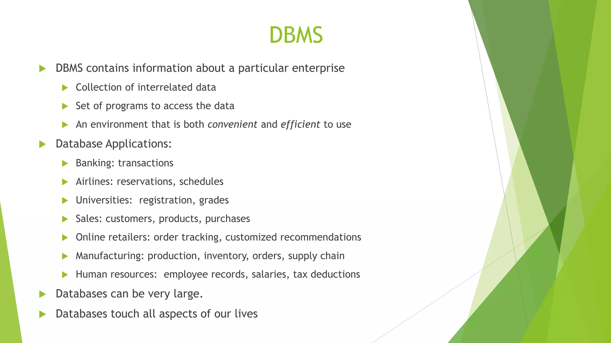
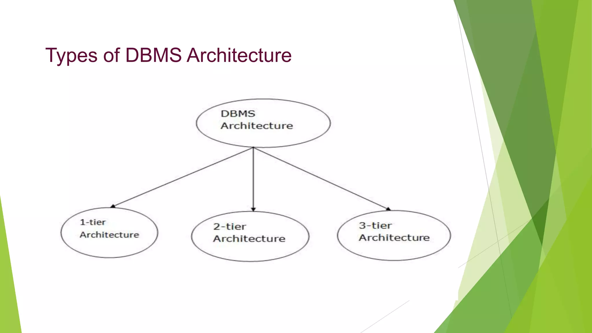
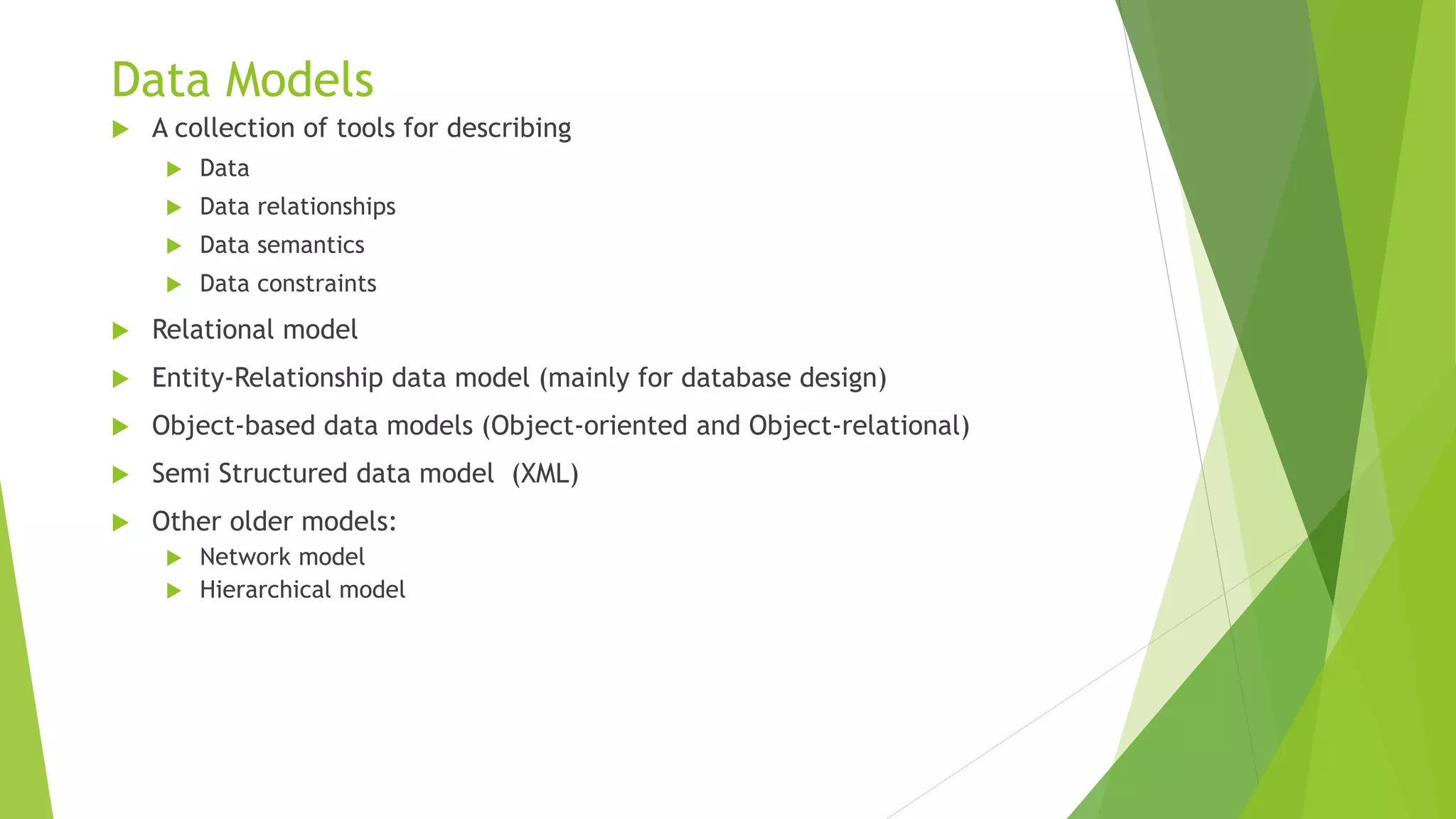
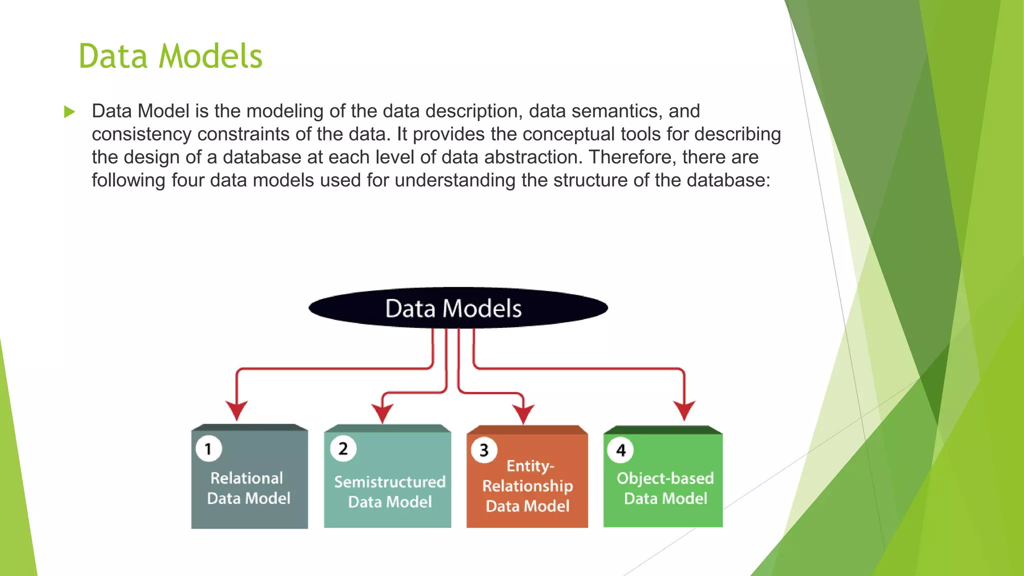
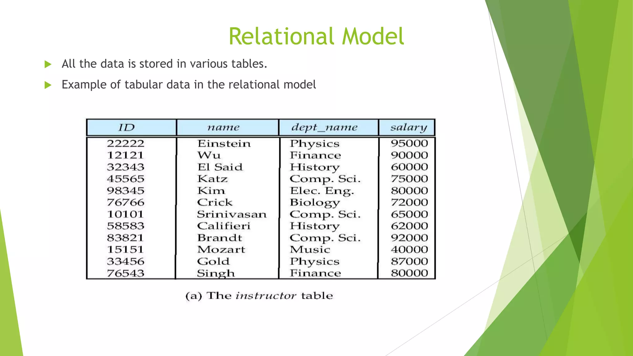
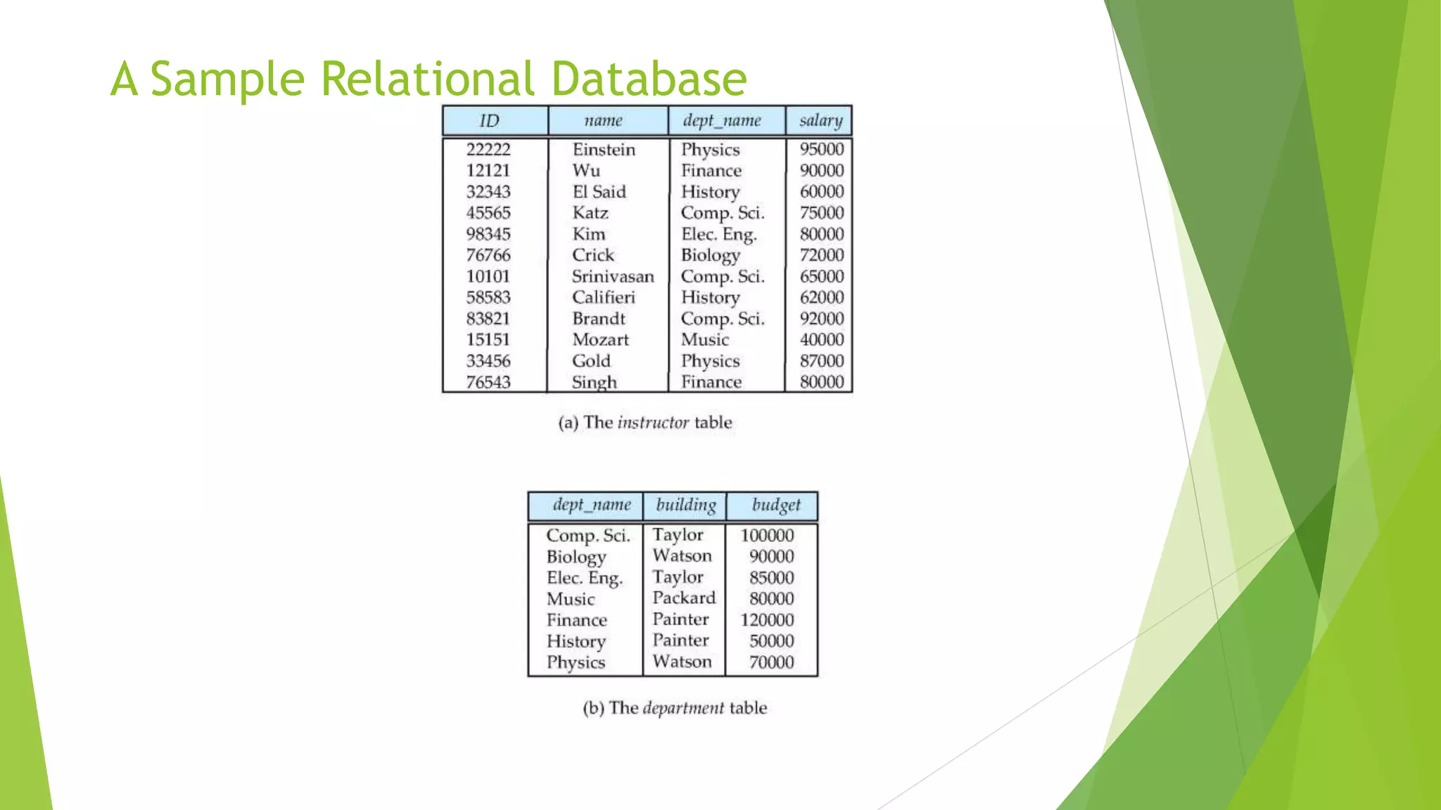
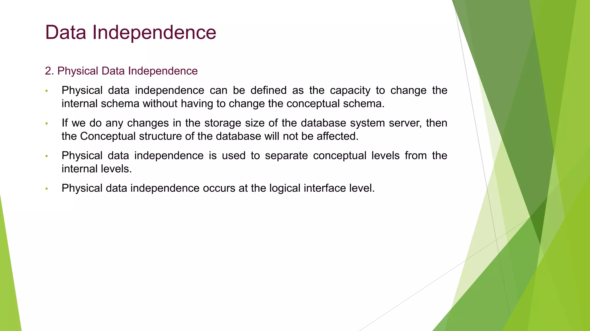
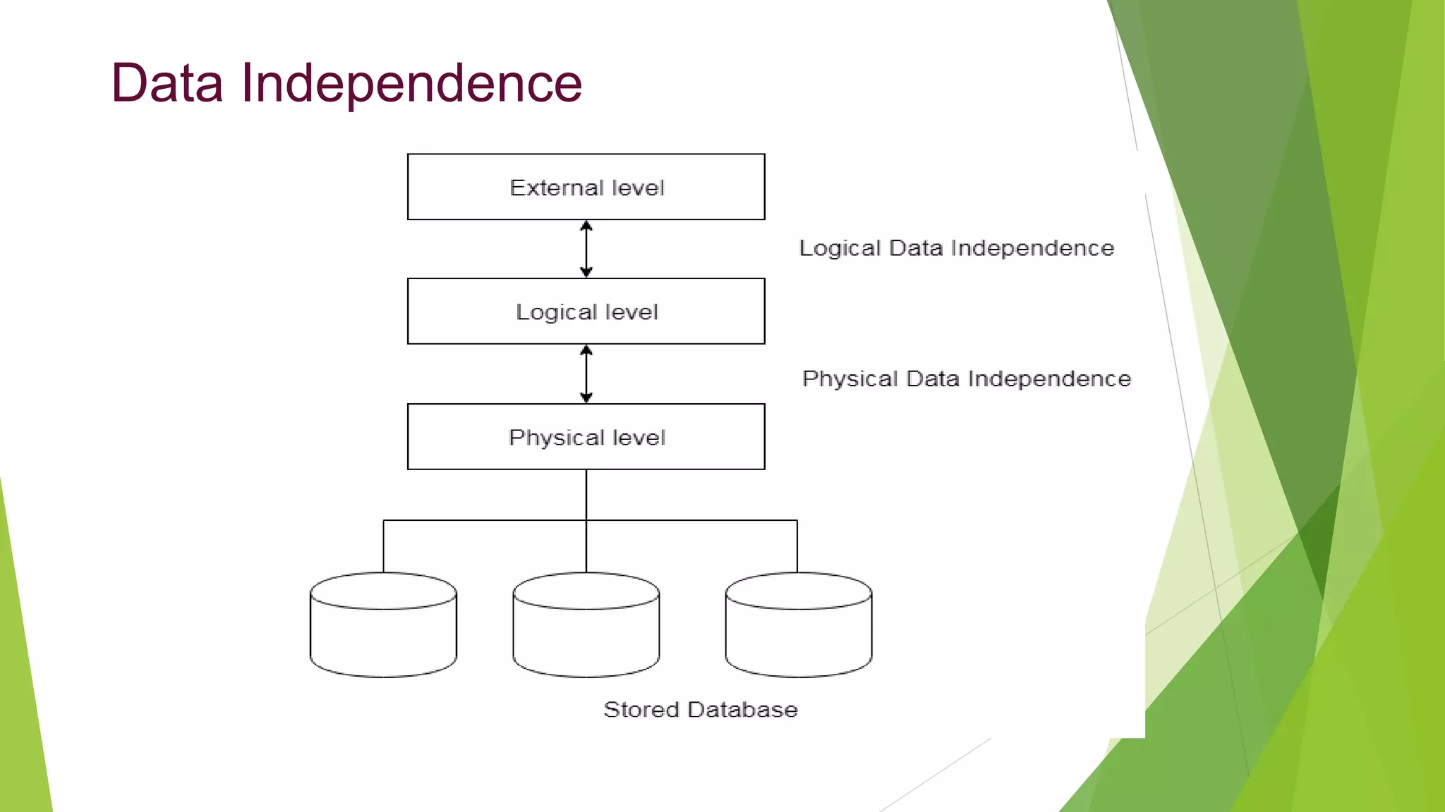
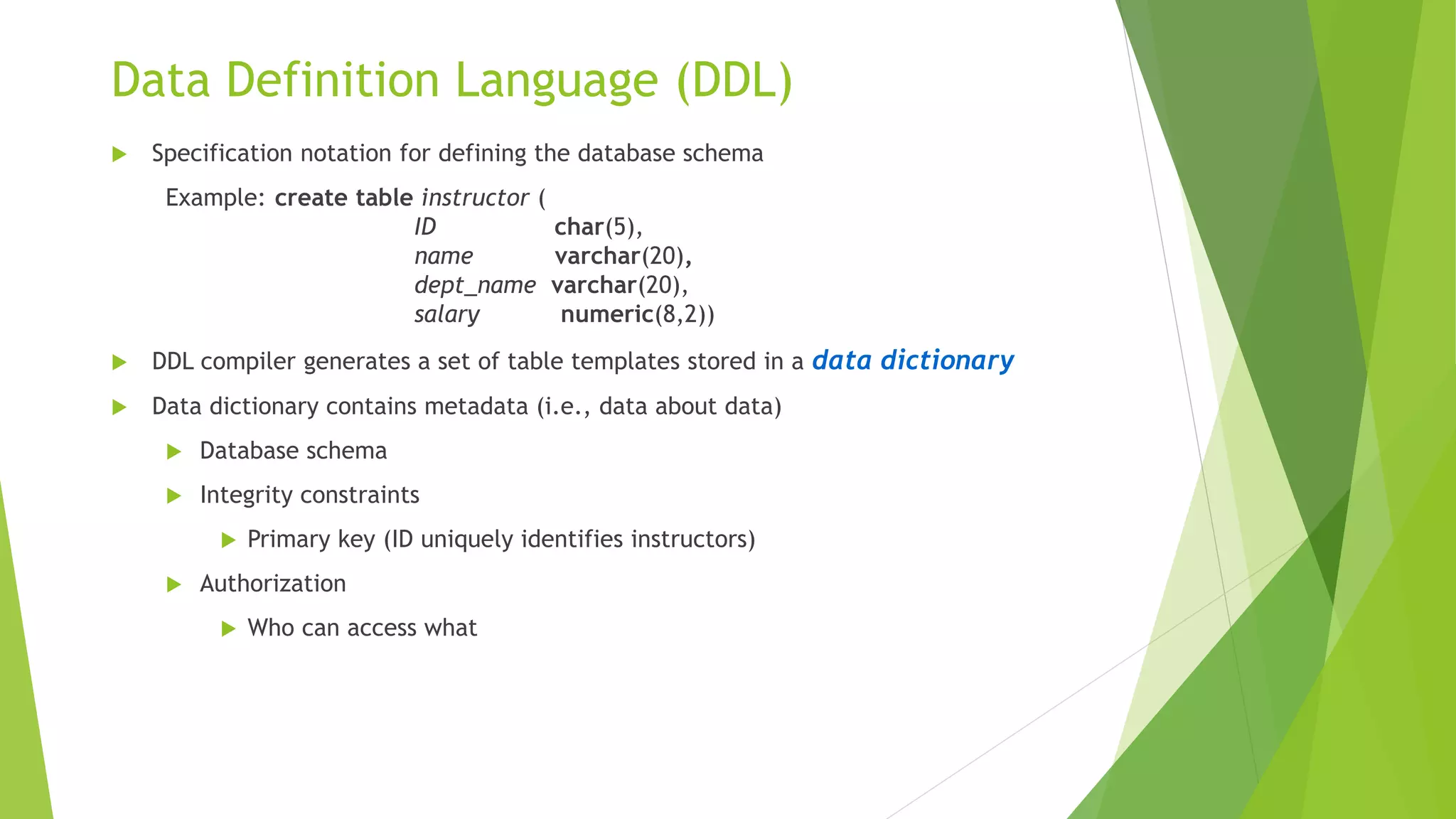
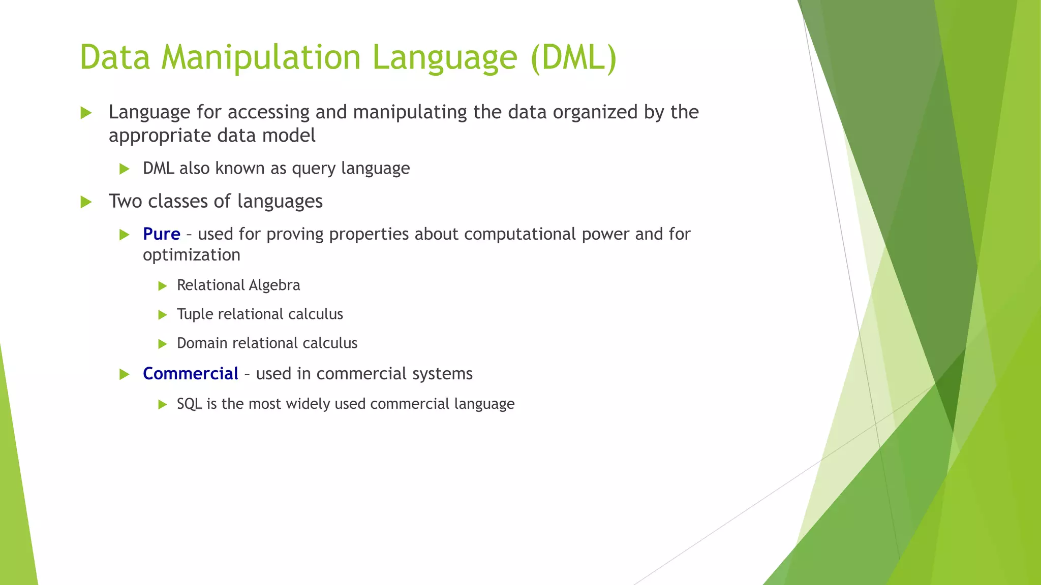
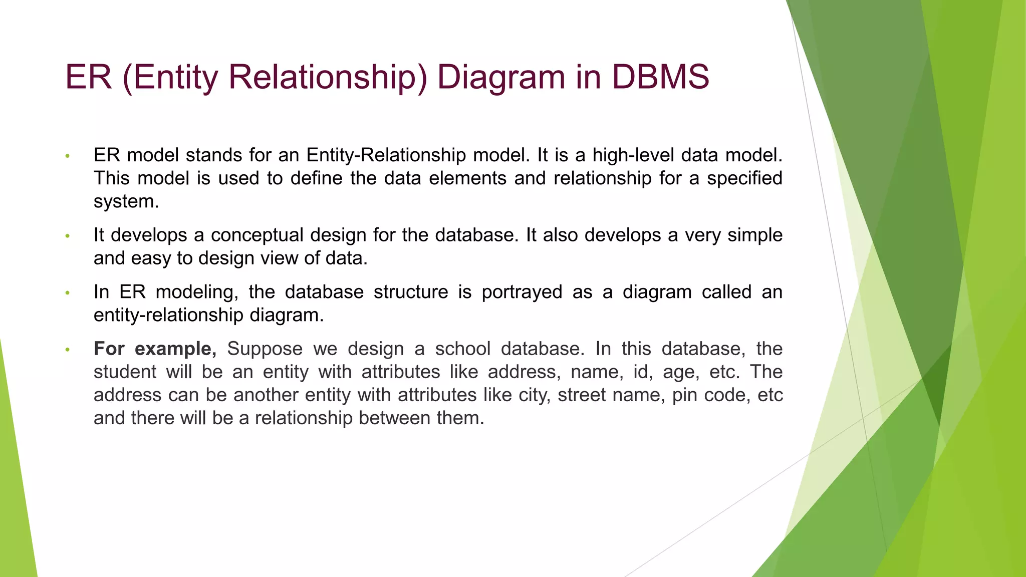
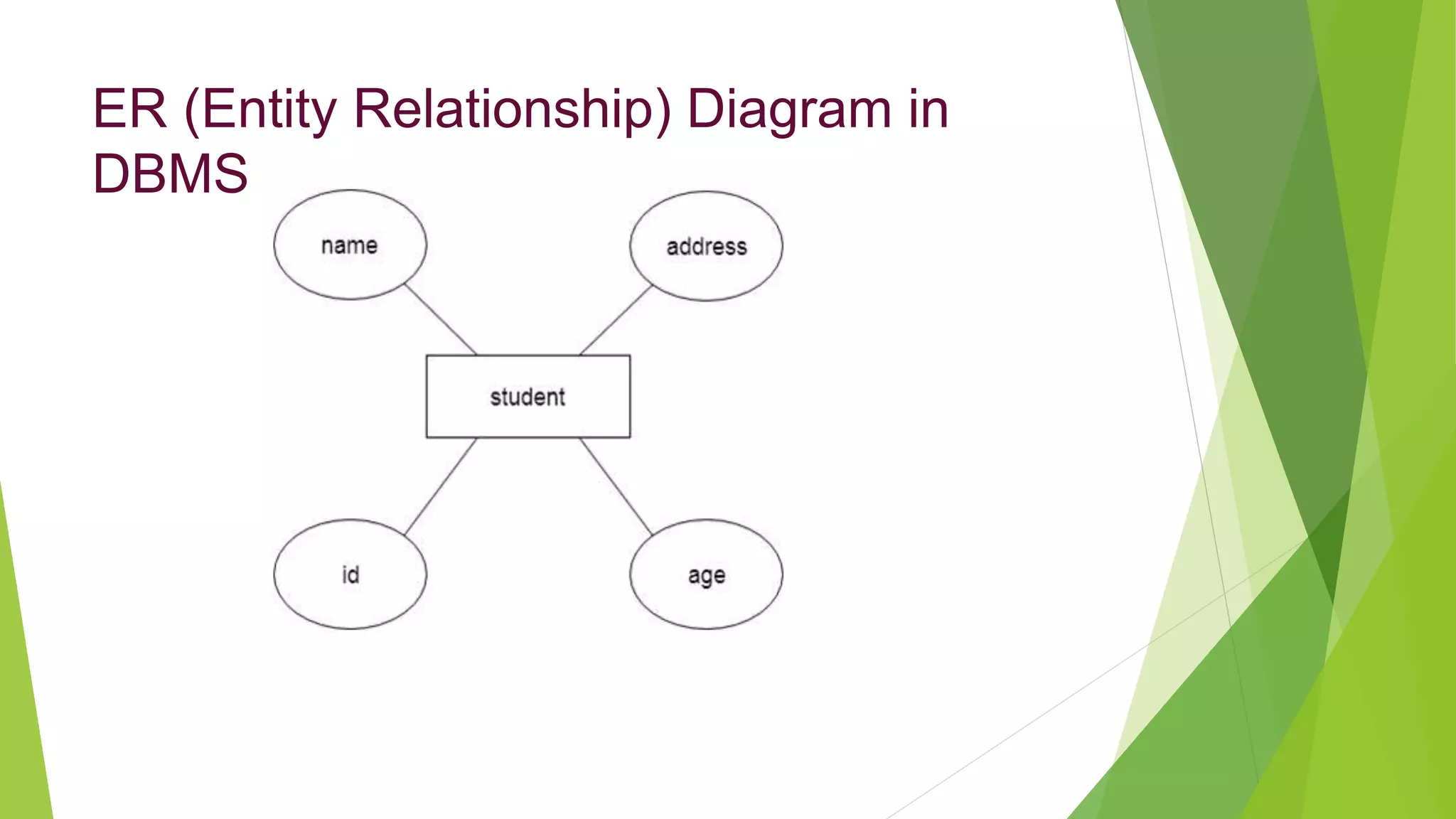
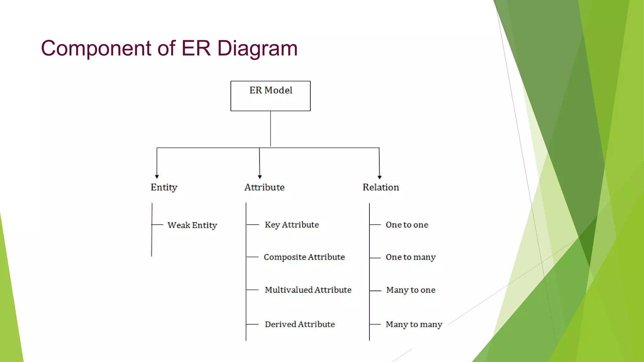
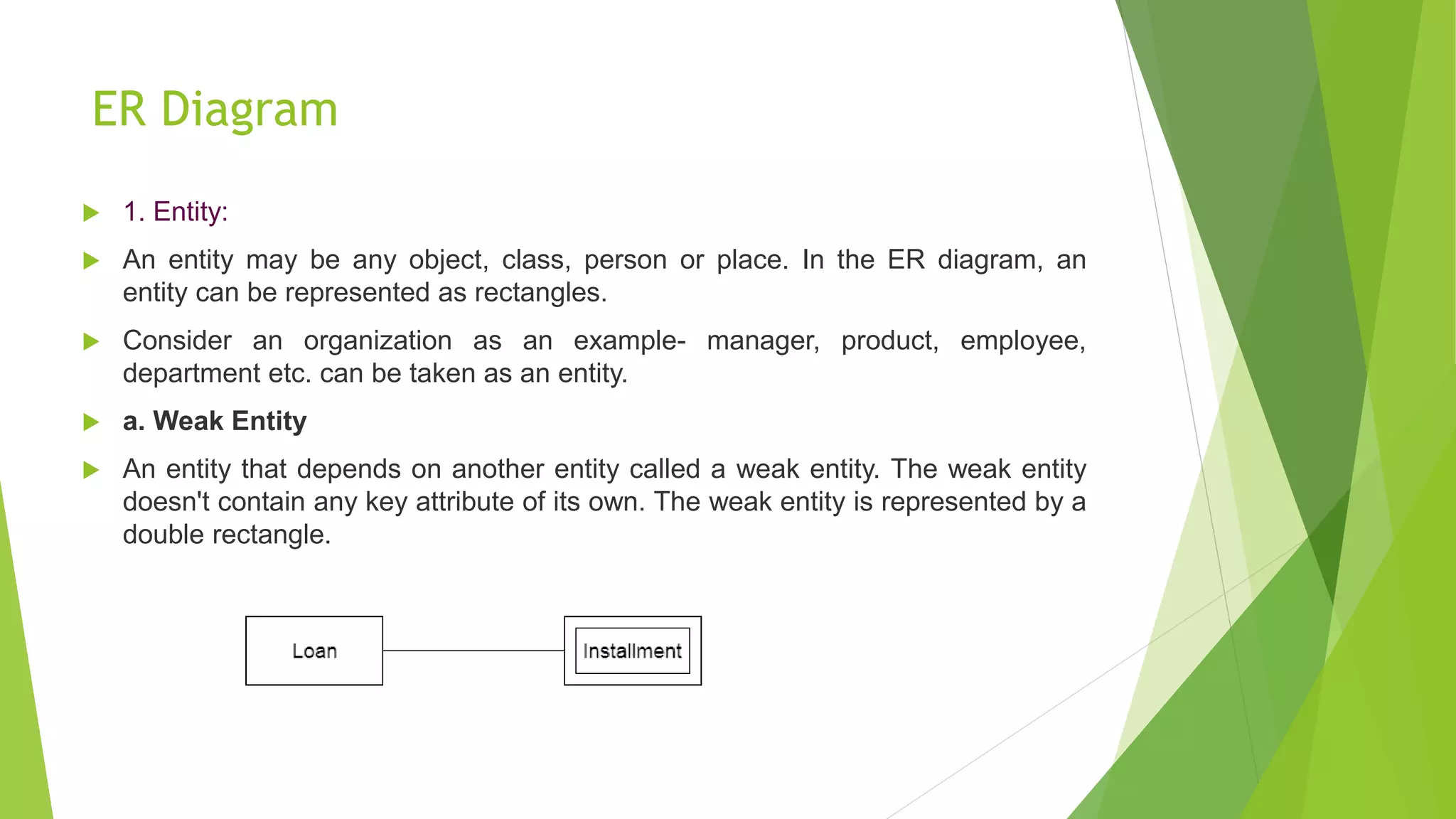
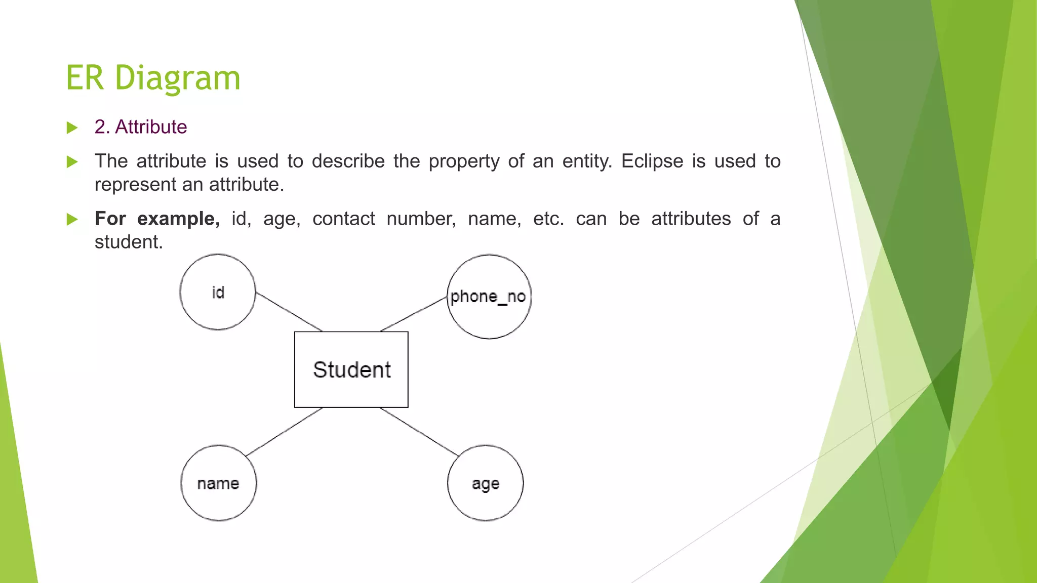
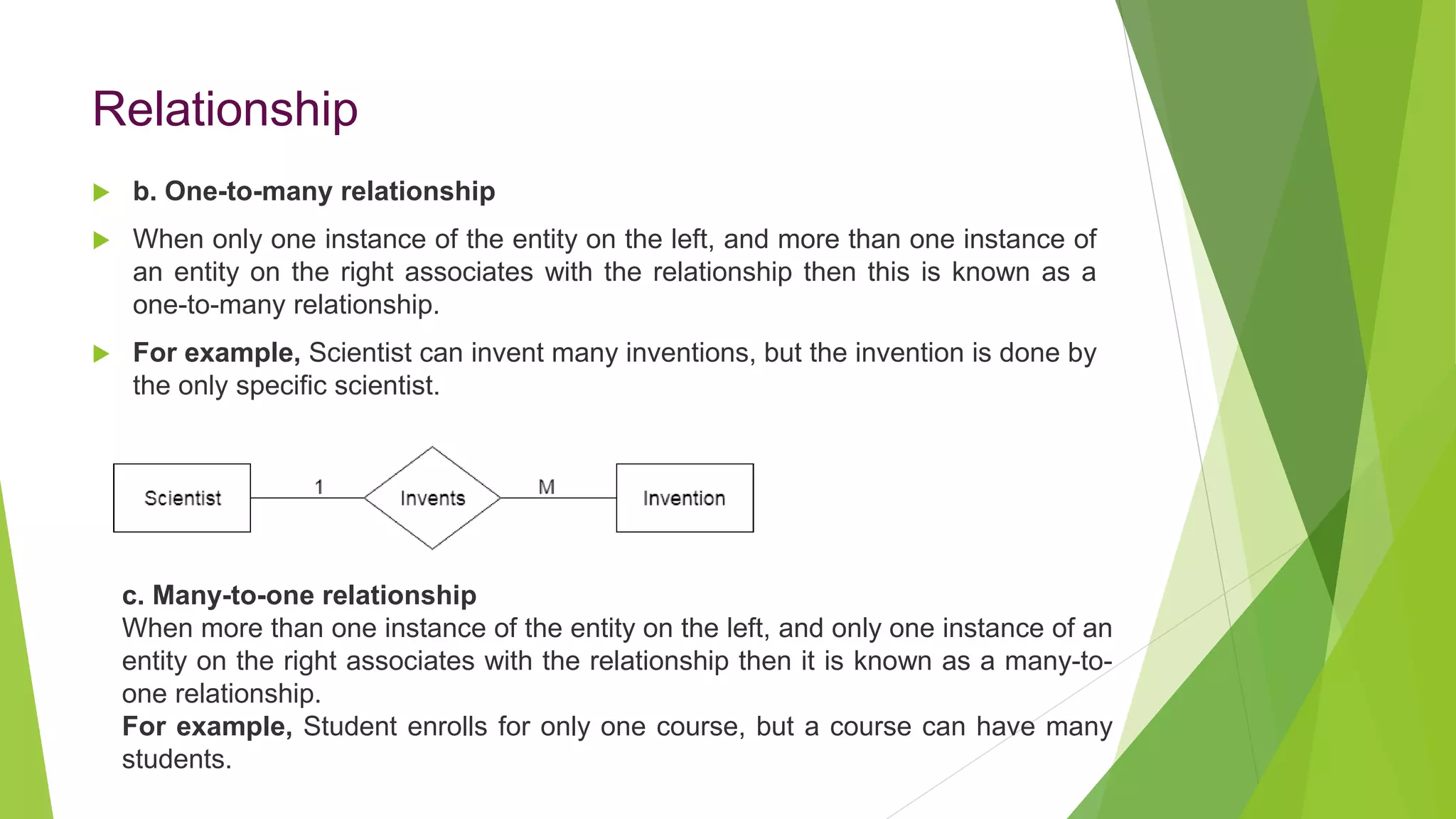
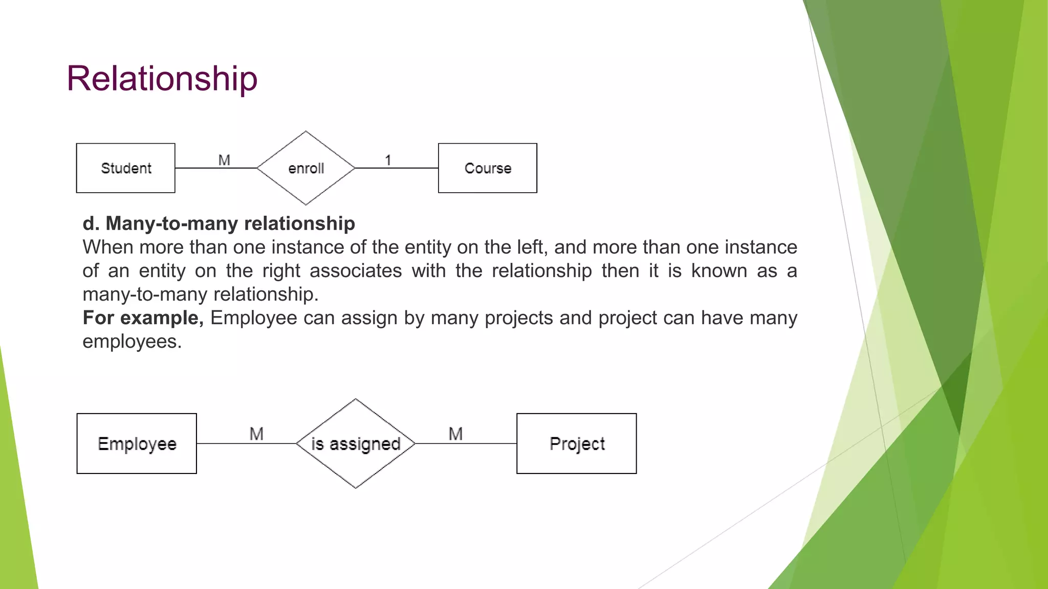
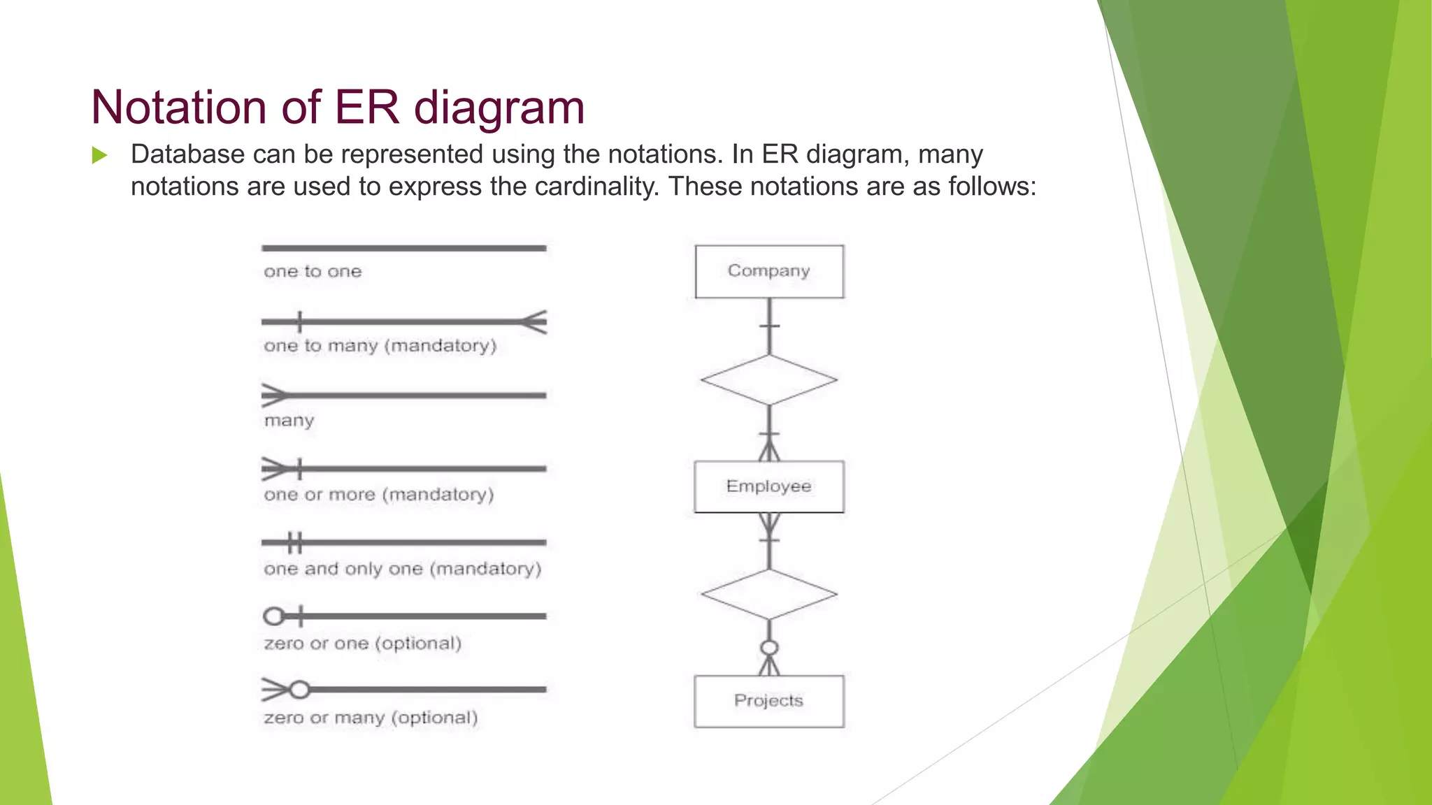
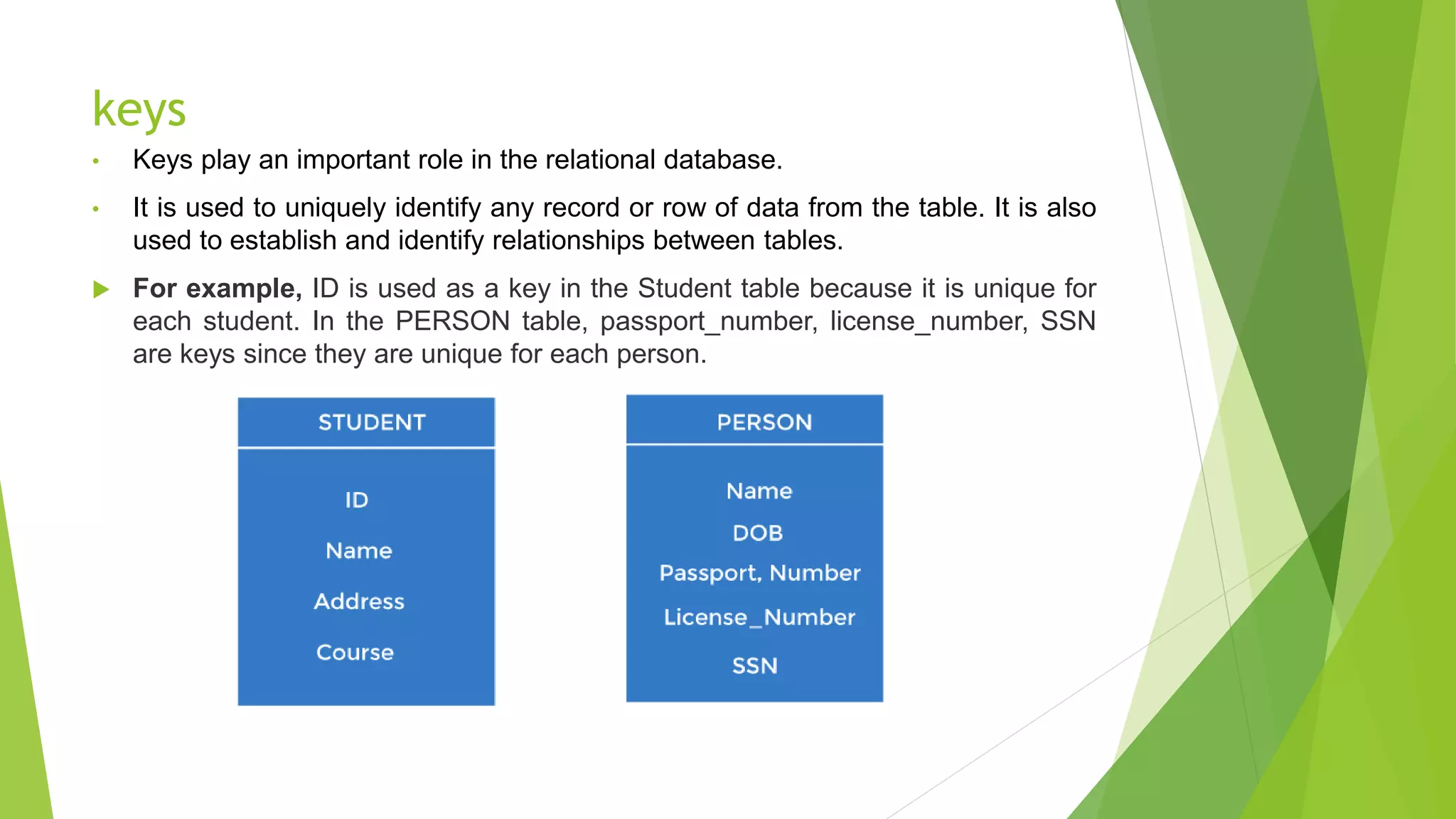
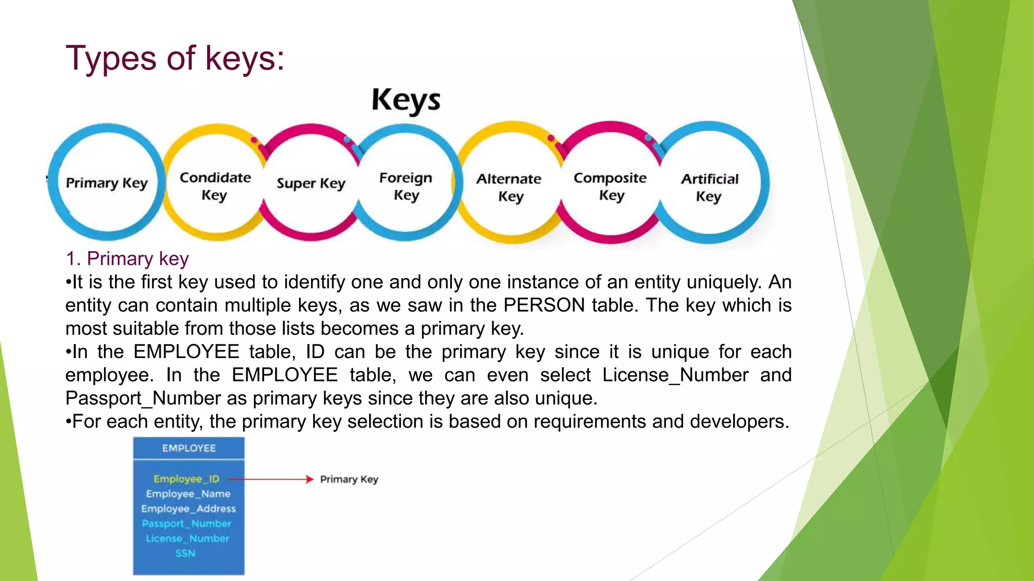
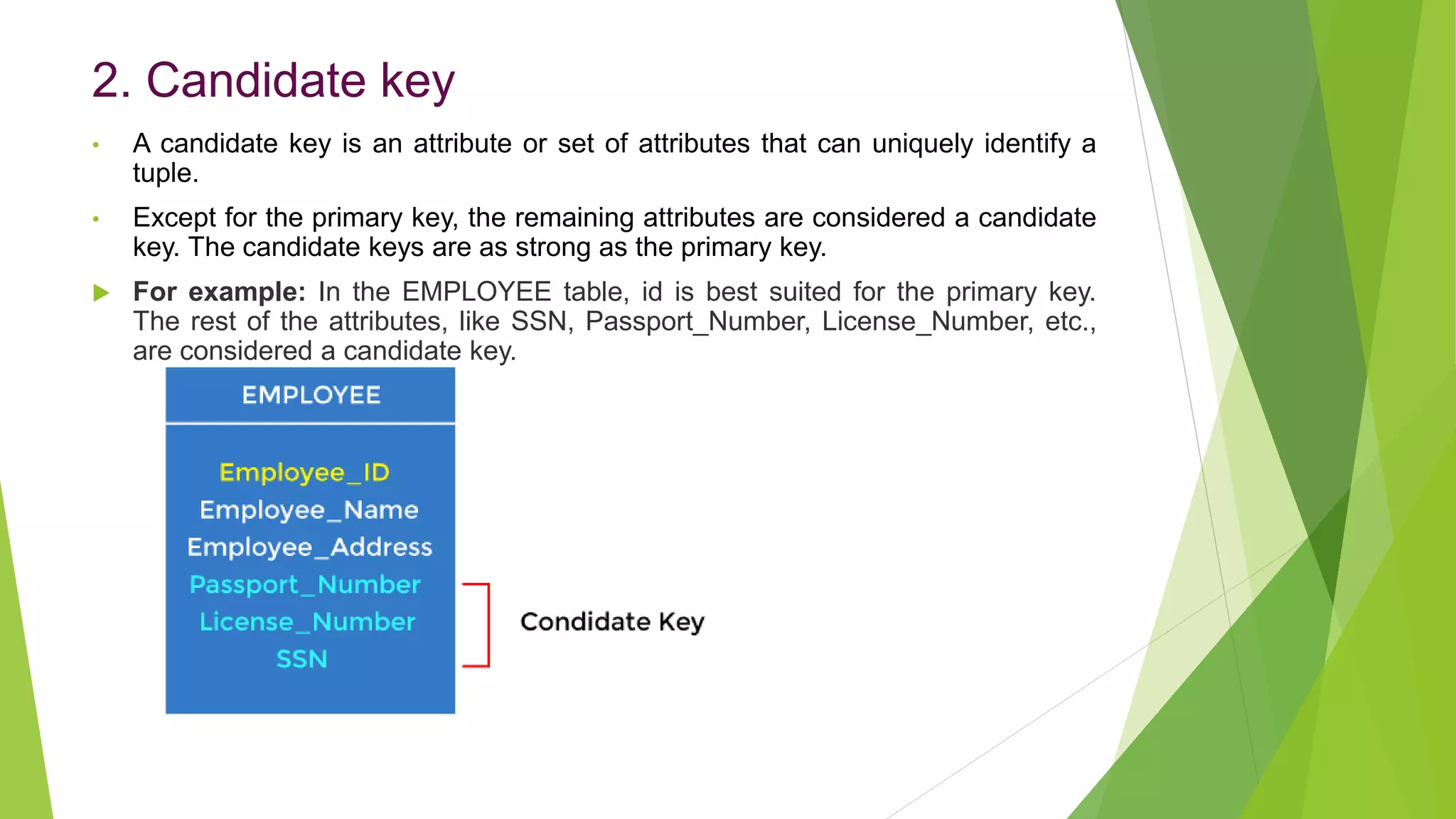
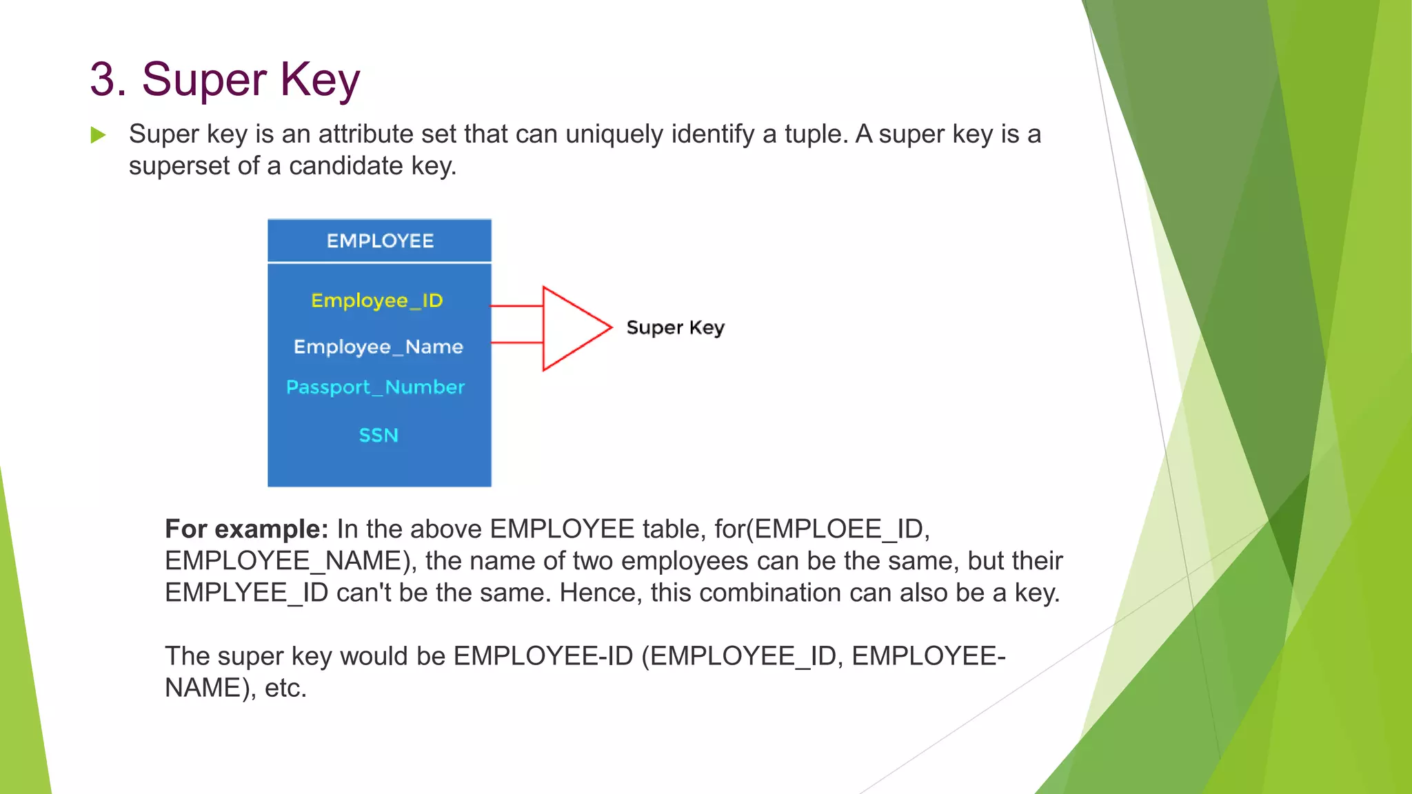
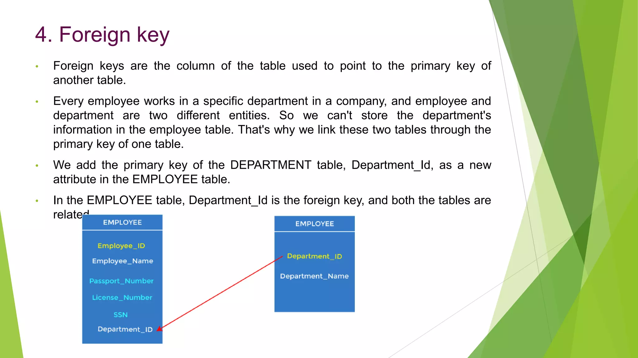
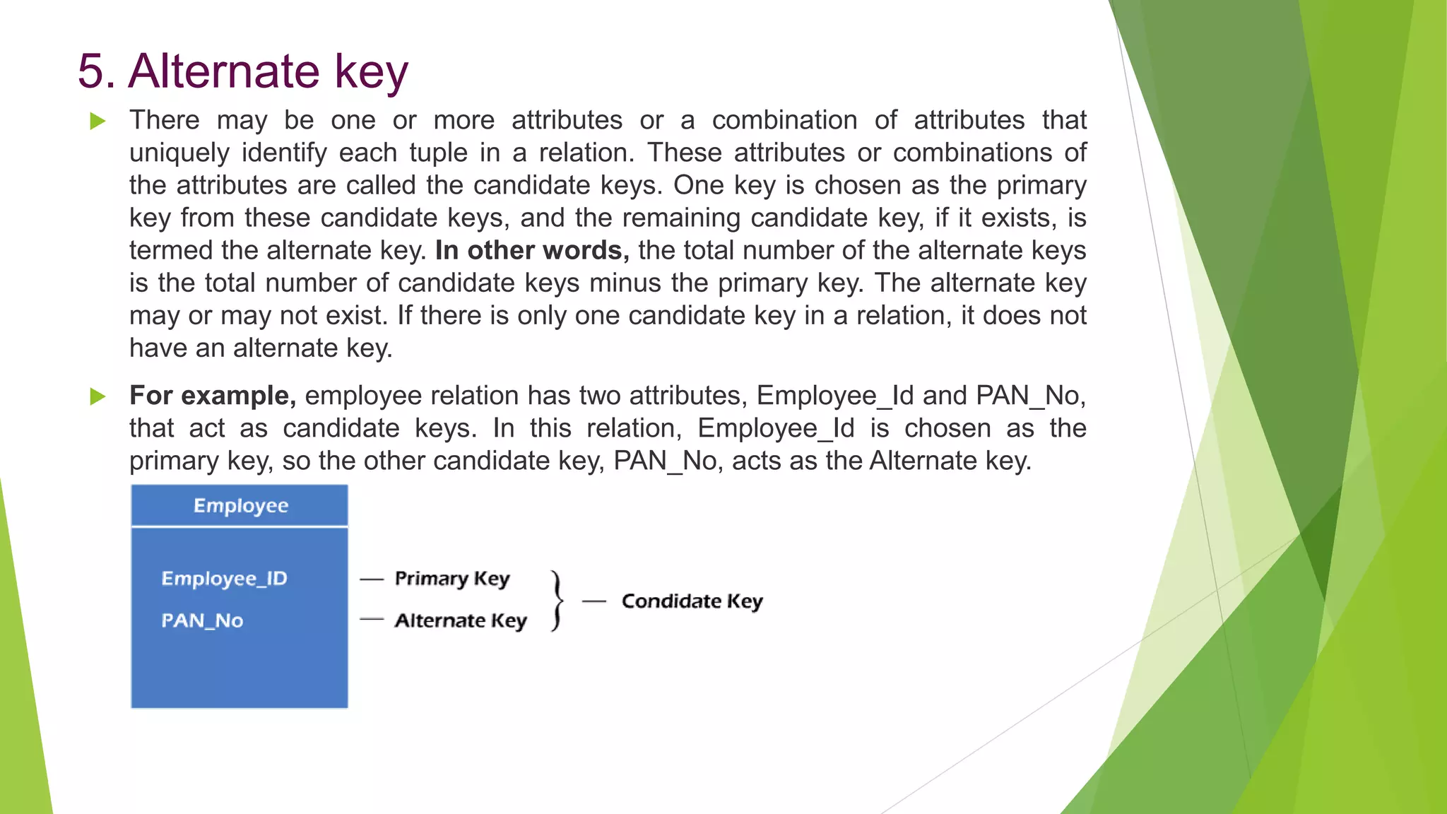
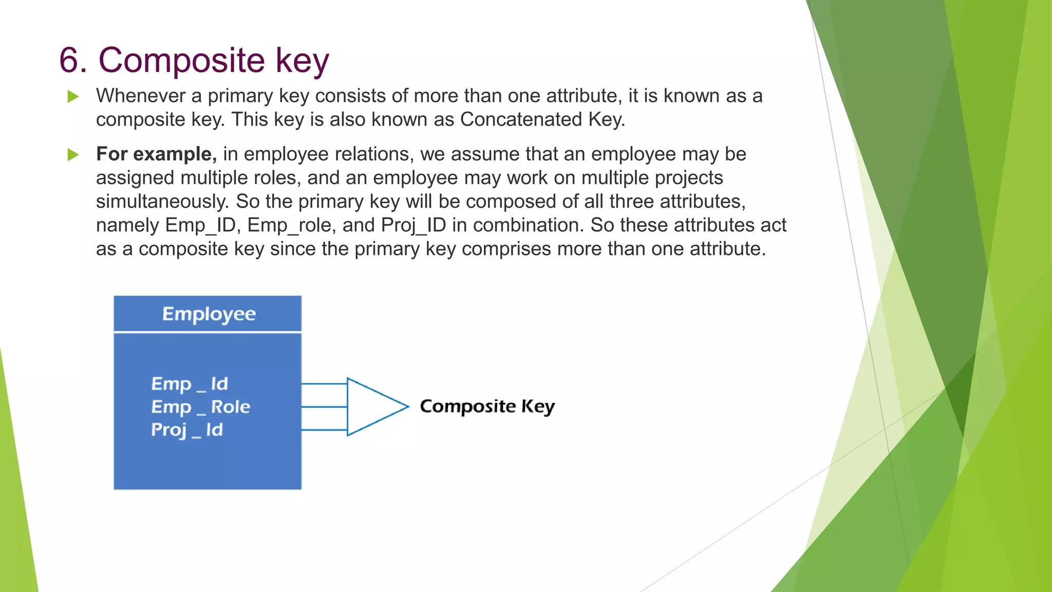
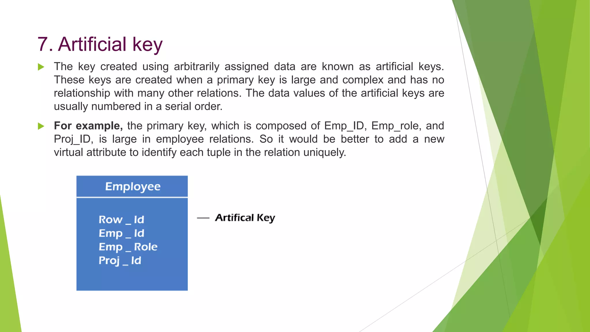
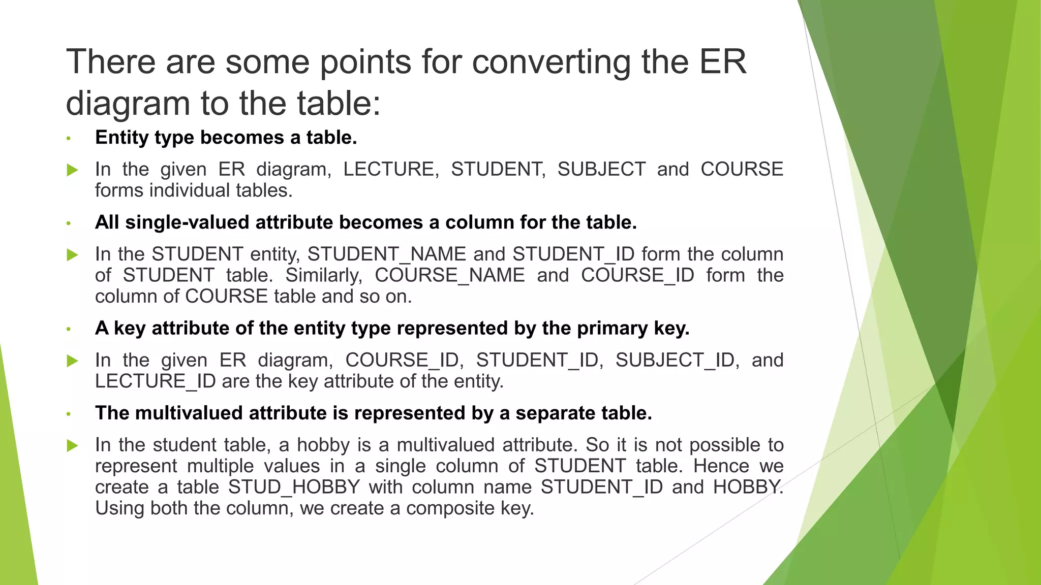
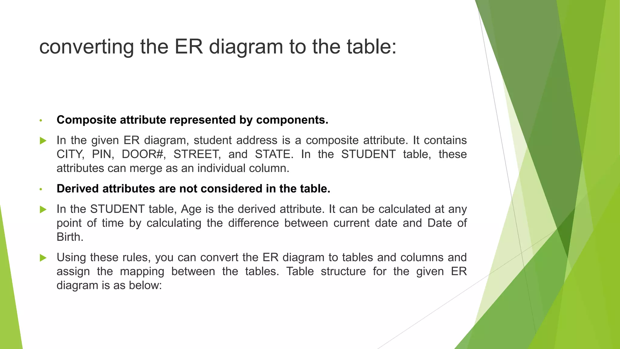
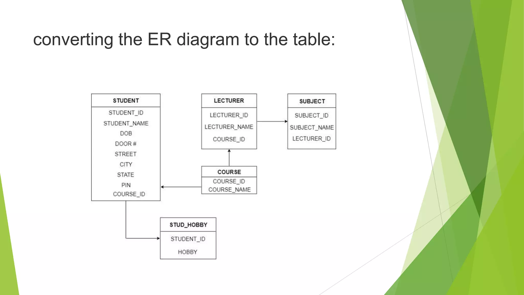
The document provides an overview of database management systems (DBMS). It discusses the need for DBMS, different database architectures including centralized, client-server and distributed. It also covers data models, ER diagrams, relational models, and SQL. Key advantages of DBMS over file systems include reducing data redundancy, improving data integrity and security, and enabling concurrent access.
2. Unit-I
Introduction
• The Need for Databases
• Database Architecture
• Data Models
• Data model Schema and Instance
• Data Independence
• DDL,DML & SQL
• ER Diagram
• Mapping Constraints
3. DBMS
DBMS contains information about a particular enterprise
Collection of interrelated data
Set of programs to access the data
An environment that is both convenient and efficient to use
Database Applications:
Banking: transactions
Airlines: reservations, schedules
Universities: registration, grades
Sales: customers, products, purchases
Online retailers: order tracking, customized recommendations
Manufacturing: production, inventory, orders, supply chain
Human resources: employee records, salaries, tax deductions
Databases can be very large.
Databases touch all aspects of our lives
4. University Database Example
Application program examples
Add new students, instructors, and courses
Register students for courses, and generate class rosters
Assign grades to students, compute grade point averages (GPA) and generate transcripts
In the early days, database applications were built directly on top of file systems
5. File System Vs DBMS
File based systems were an early attempt to computerize the manual system. It
is also called a traditional based approach in which a decentralized approach
was taken where each department stored and controlled its own data with the
help of a data processing specialist.
The main role of a data processing specialist was to create the necessary
computer file structures, and also manage the data within structures and design
some application programs that create reports based on file data.
So to overcome data redundency, we need to create a centralized system, i.e.
DBMS approach.
6. Drawbacks of using file systems to store data
Data redundancy and inconsistency
Multiple file formats, duplication of information in different files
Difficulty in accessing data
Need to write a new program to carry out each new task
Data isolation
Multiple files and formats
Integrity problems
Integrity constraints (e.g., account balance > 0) become “buried” in program code
rather than being stated explicitly
Hard to add new constraints or change existing ones
Atomicity of updates
Failures may leave database in an inconsistent state with partial updates carried out
Example: Transfer of funds from one account to another should either complete or not
happen at all
7. Drawbacks of using file systems to
store data
Concurrent access by multiple users
Concurrent access needed for performance
Uncontrolled concurrent accesses can lead to inconsistencies
Example: Two people reading a balance (say 100) and updating it by withdrawing money
(say 50 each) at the same time
Security problems
Hard to provide user access to some, but not all, data
Database systems offer solutions to all the above problems
8. Database Architecture
The architecture of a database systems is greatly influenced by
the underlying computer system on which the database is running:
Centralized
Client-server
Parallel (multi-processor)
Distributed
The DBMS design depends upon its architecture. The basic client/server
architecture is used to deal with a large number of PCs, web servers, database
servers and other components that are connected with networks.
The client/server architecture consists of many PCs and a workstation which are
connected via the network.
10. 1-Tier Architecture
• In this architecture, the database is directly available to the user. It means
the user can directly sit on the DBMS and uses it.
• Any changes done here will directly be done on the database itself. It doesn't
provide a handy tool for end users.
• The 1-Tier architecture is used for development of the local application,
where programmers can directly communicate with the database for the
quick response.
11. 2-Tier Architecture
• The 2-Tier architecture is same as basic client-server. In the two-tier
architecture, applications on the client end can directly communicate with the
database at the server side. For this interaction, API's like: ODBC, JDBC are
used.
• The user interfaces and application programs are run on the client-side.
• The server side is responsible to provide the functionalities like: query
processing and transaction management.
• To communicate with the DBMS, client-side application establishes a connection
with the server side.
12. 3-Tier Architecture
• The 3-Tier architecture contains another layer between the client and server. In
this architecture, client can't directly communicate with the server.
• The application on the client-end interacts with an application server which
further communicates with the database system.
• End user has no idea about the existence of the database beyond the
application server. The database also has no idea about any other user beyond
the application.
• The 3-Tier architecture is used in case of large web application.
13. Data Models
A collection of tools for describing
Data
Data relationships
Data semantics
Data constraints
Relational model
Entity-Relationship data model (mainly for database design)
Object-based data models (Object-oriented and Object-relational)
Semi Structured data model (XML)
Other older models:
Network model
Hierarchical model
14. Data Models
Data Model is the modeling of the data description, data semantics, and
consistency constraints of the data. It provides the conceptual tools for describing
the design of a database at each level of data abstraction. Therefore, there are
following four data models used for understanding the structure of the database:
15. Relational Model
All the data is stored in various tables.
Example of tabular data in the relational model
17. Data Model:
1) Relational Data Model: This type of model designs the data in the form of rows
and columns within a table. Thus, a relational model uses tables for representing
data and in-between relationships. Tables are also called relations. This model was
initially described by Edgar F. Codd, in 1969. The relational data model is the
widely used model which is primarily used by commercial data processing
applications.
2) Entity-Relationship Data Model: An ER model is the logical representation of
data as objects and relationships among them. These objects are known as
entities, and relationship is an association among these entities. This model was
designed by Peter Chen and published in 1976 papers. It was widely used in
database designing. A set of attributes describe the entities. For example,
student_name, student_id describes the 'student' entity. A set of the same type of
entities is known as an 'Entity set', and the set of the same type of relationships is
known as 'relationship set'.
18. Data Model:
3) Object-based Data Model: An extension of the ER model with notions of
functions, encapsulation, and object identity, as well. This model supports a rich
type system that includes structured and collection types. Thus, in 1980s,
various database systems following the object-oriented approach were
developed. Here, the objects are nothing but the data carrying its properties.
4) Semistructured Data Model: This type of data model is different from the
other three data models (explained above). The semistructured data model
allows the data specifications at places where the individual data items of the
same type may have different attributes sets. The Extensible Markup Language,
also known as XML, is widely used for representing the semistructured data.
Although XML was initially designed for including the markup information to the
text document, it gains importance because of its application in the exchange of
data.
19. Data model Schema and Instance
• The data which is stored in the database at a particular moment of time is called an
instance of the database.
• The overall design of a database is called schema.
• A database schema is the skeleton structure of the database. It represents the logical
view of the entire database.
• A schema contains schema objects like table, foreign key, primary key, views, columns,
data types, stored procedure, etc.
• A database schema can be represented by using the visual diagram. That diagram
shows the database objects and relationship with each other.
• A database schema is designed by the database designers to help programmers whose
software will interact with the database. The process of database creation is called data
modeling.
A schema diagram can display only some aspects of a schema like the name of record
type, data type, and constraints. Other aspects can't be specified through the schema
diagram. For example, the given figure neither show the data type of each data item nor
the relationship among various files.
In the database, actual data changes quite frequently. For example, in the given figure,
the database changes whenever we add a new grade or add a student. The data at a
particular moment of time is called the instance of the database.
20. Data Independence
Data Independence
• Data independence can be explained using the three-schema architecture.
• Data independence refers characteristic of being able to modify the schema at
one level of the database system without altering the schema at the next higher
level.
There are two types of data independence:
1. Logical Data Independence
• Logical data independence refers characteristic of being able to change the
conceptual schema without having to change the external schema.
• Logical data independence is used to separate the external level from the
conceptual view.
• If we do any changes in the conceptual view of the data, then the user view of
the data would not be affected.
• Logical data independence occurs at the user interface level.
21. Data Independence
2. Physical Data Independence
• Physical data independence can be defined as the capacity to change the
internal schema without having to change the conceptual schema.
• If we do any changes in the storage size of the database system server, then
the Conceptual structure of the database will not be affected.
• Physical data independence is used to separate conceptual levels from the
internal levels.
• Physical data independence occurs at the logical interface level.
23. Data Definition Language (DDL)
Specification notation for defining the database schema
Example: create table instructor (
ID char(5),
name varchar(20),
dept_name varchar(20),
salary numeric(8,2))
DDL compiler generates a set of table templates stored in a data dictionary
Data dictionary contains metadata (i.e., data about data)
Database schema
Integrity constraints
Primary key (ID uniquely identifies instructors)
Authorization
Who can access what
24. Data Manipulation Language (DML)
Language for accessing and manipulating the data organized by the
appropriate data model
DML also known as query language
Two classes of languages
Pure – used for proving properties about computational power and for
optimization
Relational Algebra
Tuple relational calculus
Domain relational calculus
Commercial – used in commercial systems
SQL is the most widely used commercial language
25. SQL
The most widely used commercial language
SQL is NOT a Turing machine equivalent language
To be able to compute complex functions SQL is usually embedded in some
higher-level language
Application programs generally access databases through one of
Language extensions to allow embedded SQL
Application program interface (e.g., ODBC/JDBC) which allow SQL queries to be
sent to a database
26. ER (Entity Relationship) Diagram in DBMS
• ER model stands for an Entity-Relationship model. It is a high-level data model.
This model is used to define the data elements and relationship for a specified
system.
• It develops a conceptual design for the database. It also develops a very simple
and easy to design view of data.
• In ER modeling, the database structure is portrayed as a diagram called an
entity-relationship diagram.
• For example, Suppose we design a school database. In this database, the
student will be an entity with attributes like address, name, id, age, etc. The
address can be another entity with attributes like city, street name, pin code, etc
and there will be a relationship between them.
29. ER Diagram
1. Entity:
An entity may be any object, class, person or place. In the ER diagram, an
entity can be represented as rectangles.
Consider an organization as an example- manager, product, employee,
department etc. can be taken as an entity.
a. Weak Entity
An entity that depends on another entity called a weak entity. The weak entity
doesn't contain any key attribute of its own. The weak entity is represented by a
double rectangle.
30. ER Diagram
2. Attribute
The attribute is used to describe the property of an entity. Eclipse is used to
represent an attribute.
For example, id, age, contact number, name, etc. can be attributes of a
student.
31. ER Diagram
a. Key Attribute
The key attribute is used to represent the main characteristics of an entity. It
represents a primary key. The key attribute is represented by an ellipse with the
text underlined.
b. Composite Attribute
An attribute that composed of many other attributes is known as a composite
attribute. The composite attribute is represented by an ellipse, and those
ellipses are connected with an ellipse.
c. Multivalued Attribute
An attribute can have more than one value. These attributes are known as a
multivalued attribute. The double oval is used to represent multivalued attribute.
d. Derived Attribute
An attribute that can be derived from other attribute is known as a derived
attribute. It can be represented by a dashed ellipse.
33. ER Diagram
For example, A person's age changes over time and can
be derived from another attribute like Date of birth.
34. Relationship
3. Relationship
A relationship is used to describe the relation between entities. Diamond or
rhombus is used to represent the relationship.
Types of relationship are as follows:
a. One-to-One Relationship
When only one instance of an entity is associated with the relationship, then it is
known as one to one relationship.
For example, A female can marry to one male, and a male can marry to one
female.
35. Relationship
b. One-to-many relationship
When only one instance of the entity on the left, and more than one instance of
an entity on the right associates with the relationship then this is known as a
one-to-many relationship.
For example, Scientist can invent many inventions, but the invention is done by
the only specific scientist.
c. Many-to-one relationship
When more than one instance of the entity on the left, and only one instance of an
entity on the right associates with the relationship then it is known as a many-to-
one relationship.
For example, Student enrolls for only one course, but a course can have many
students.
36. Relationship
d. Many-to-many relationship
When more than one instance of the entity on the left, and more than one instance
of an entity on the right associates with the relationship then it is known as a
many-to-many relationship.
For example, Employee can assign by many projects and project can have many
employees.
37. Notation of ER diagram
Database can be represented using the notations. In ER diagram, many
notations are used to express the cardinality. These notations are as follows:
38. Cardinality in DBMS (Mapping Constraints)
DBMS
DBMS stands for Database Management System, which is a tool, or a software
used to do various operations on a Database like the Creation of the Database,
Deletion of the Database, or Updating the current Database. To simplify
processing and data querying, the most popular types of Databases currently in
use typically model their data as rows and columns in a set of tables. The data
may then be handled, updated, regulated, and structured with ease. For writing
and querying data, most Databases employ Structured Query Language (SQL).
Cardinality
Cardinality means how the entities are arranged to each other or what is the
relationship structure between entities in a relationship set. In a Database
Management System, Cardinality represents a number that denotes how many
times an entity is participating with another entity in a relationship set. The
Cardinality of DBMS is a very important attribute in representing the structure of a
Database. In a table, the number of rows or tuples represents the Cardinality.
39. Cardinality Ratio
Cardinality Ratio
Cardinality ratio is also called Cardinality Mapping, which represents the
mapping of one entity set to another entity set in a relationship set. We generally
take the example of a binary relationship set where two entities are mapped to
each other.
Cardinality is very important in the Database of various businesses. For example,
if we want to track the purchase history of each customer then we can use the
one-to-many cardinality to find the data of a specific customer. The Cardinality
model can be used in Databases by Database Managers for a variety of
purposes, but corporations often use it to evaluate customer or inventory data.
There are four types of Cardinality Mapping in Database Management Systems:
1. One to one
2. Many to one
3. One to many
4. Many to many
40. keys
• Keys play an important role in the relational database.
• It is used to uniquely identify any record or row of data from the table. It is also
used to establish and identify relationships between tables.
For example, ID is used as a key in the Student table because it is unique for
each student. In the PERSON table, passport_number, license_number, SSN
are keys since they are unique for each person.
41. Types of keys:
1. Primary key
•It is the first key used to identify one and only one instance of an entity uniquely. An
entity can contain multiple keys, as we saw in the PERSON table. The key which is
most suitable from those lists becomes a primary key.
•In the EMPLOYEE table, ID can be the primary key since it is unique for each
employee. In the EMPLOYEE table, we can even select License_Number and
Passport_Number as primary keys since they are also unique.
•For each entity, the primary key selection is based on requirements and developers.
42. 2. Candidate key
• A candidate key is an attribute or set of attributes that can uniquely identify a
tuple.
• Except for the primary key, the remaining attributes are considered a candidate
key. The candidate keys are as strong as the primary key.
For example: In the EMPLOYEE table, id is best suited for the primary key.
The rest of the attributes, like SSN, Passport_Number, License_Number, etc.,
are considered a candidate key.
43. 3. Super Key
Super key is an attribute set that can uniquely identify a tuple. A super key is a
superset of a candidate key.
For example: In the above EMPLOYEE table, for(EMPLOEE_ID,
EMPLOYEE_NAME), the name of two employees can be the same, but their
EMPLYEE_ID can't be the same. Hence, this combination can also be a key.
The super key would be EMPLOYEE-ID (EMPLOYEE_ID, EMPLOYEE-
NAME), etc.
44. 4. Foreign key
• Foreign keys are the column of the table used to point to the primary key of
another table.
• Every employee works in a specific department in a company, and employee and
department are two different entities. So we can't store the department's
information in the employee table. That's why we link these two tables through the
primary key of one table.
• We add the primary key of the DEPARTMENT table, Department_Id, as a new
attribute in the EMPLOYEE table.
• In the EMPLOYEE table, Department_Id is the foreign key, and both the tables are
related.
45. 5. Alternate key
There may be one or more attributes or a combination of attributes that
uniquely identify each tuple in a relation. These attributes or combinations of
the attributes are called the candidate keys. One key is chosen as the primary
key from these candidate keys, and the remaining candidate key, if it exists, is
termed the alternate key. In other words, the total number of the alternate keys
is the total number of candidate keys minus the primary key. The alternate key
may or may not exist. If there is only one candidate key in a relation, it does not
have an alternate key.
For example, employee relation has two attributes, Employee_Id and PAN_No,
that act as candidate keys. In this relation, Employee_Id is chosen as the
primary key, so the other candidate key, PAN_No, acts as the Alternate key.
46. 6. Composite key
Whenever a primary key consists of more than one attribute, it is known as a
composite key. This key is also known as Concatenated Key.
For example, in employee relations, we assume that an employee may be
assigned multiple roles, and an employee may work on multiple projects
simultaneously. So the primary key will be composed of all three attributes,
namely Emp_ID, Emp_role, and Proj_ID in combination. So these attributes act
as a composite key since the primary key comprises more than one attribute.
47. 7. Artificial key
The key created using arbitrarily assigned data are known as artificial keys.
These keys are created when a primary key is large and complex and has no
relationship with many other relations. The data values of the artificial keys are
usually numbered in a serial order.
For example, the primary key, which is composed of Emp_ID, Emp_role, and
Proj_ID, is large in employee relations. So it would be better to add a new
virtual attribute to identify each tuple in the relation uniquely.
48. Generalization
• Generalization is like a bottom-up approach in which two or more entities of
lower level combine to form a higher level entity if they have some attributes in
common.
• In generalization, an entity of a higher level can also combine with the entities
of the lower level to form a further higher level entity.
• Generalization is more like subclass and superclass system, but the only
difference is the approach. Generalization uses the bottom-up approach.
• In generalization, entities are combined to form a more generalized entity, i.e.,
subclasses are combined to make a superclass.
For example, Faculty and Student entities can be generalized and create a
higher level entity Person.
49. Specialization
• Specialization is a top-down approach, and it is opposite to Generalization. In
specialization, one higher level entity can be broken down into two lower level
entities.
• Specialization is used to identify the subset of an entity set that shares some
distinguishing characteristics.
• Normally, the superclass is defined first, the subclass and its related attributes
are defined next, and relationship set are then added.
For example: In an Employee management system, EMPLOYEE entity can be
specialized as TESTER or DEVELOPER based on what role they play in the
company.
50. Aggregation
In aggregation, the relation between two entities is treated as a single entity. In
aggregation, relationship with its corresponding entities is aggregated into a
higher level entity.
For example: Center entity offers the Course entity act as a single entity in the
relationship which is in a relationship with another entity visitor. In the real
world, if a visitor visits a coaching center then he will never enquiry about the
Course only or just about the Center instead he will ask the enquiry about both.
51. Reduction of ER diagram to Table
The database can be represented using the notations, and these notations can
be reduced to a collection of tables.
In the database, every entity set or relationship set can be represented in
tabular form.
52. There are some points for converting the ER
diagram to the table:
• Entity type becomes a table.
In the given ER diagram, LECTURE, STUDENT, SUBJECT and COURSE
forms individual tables.
• All single-valued attribute becomes a column for the table.
In the STUDENT entity, STUDENT_NAME and STUDENT_ID form the column
of STUDENT table. Similarly, COURSE_NAME and COURSE_ID form the
column of COURSE table and so on.
• A key attribute of the entity type represented by the primary key.
In the given ER diagram, COURSE_ID, STUDENT_ID, SUBJECT_ID, and
LECTURE_ID are the key attribute of the entity.
• The multivalued attribute is represented by a separate table.
In the student table, a hobby is a multivalued attribute. So it is not possible to
represent multiple values in a single column of STUDENT table. Hence we
create a table STUD_HOBBY with column name STUDENT_ID and HOBBY.
Using both the column, we create a composite key.
53. converting the ER diagram to the table:
• Composite attribute represented by components.
In the given ER diagram, student address is a composite attribute. It contains
CITY, PIN, DOOR#, STREET, and STATE. In the STUDENT table, these
attributes can merge as an individual column.
• Derived attributes are not considered in the table.
In the STUDENT table, Age is the derived attribute. It can be calculated at any
point of time by calculating the difference between current date and Date of
Birth.
Using these rules, you can convert the ER diagram to tables and columns and
assign the mapping between the tables. Table structure for the given ER
diagram is as below:
55. Relationship of higher degree
The degree of relationship can be defined as the number of occurrences in one
entity that is associated with the number of occurrences in another entity.
There is the three degree of relationship:
1. One-to-one (1:1)
2. One-to-many (1:M)
3. Many-to-many (M:N)
1. One-to-one
• In a one-to-one relationship, one occurrence of an entity relates to only one
occurrence in another entity.
• A one-to-one relationship rarely exists in practice.
• For example: if an employee is allocated a company car then that car can only
be driven by that employee.
• Therefore, employee and company car have a one-to-one relationship.
56. Relationship of higher degree
2. One-to-many
•In a one-to-many relationship, one occurrence in an entity relates to many
occurrences in another entity.
•For example: An employee works in one department, but a department has
many employees.
•Therefore, department and employee have a one-to-many relationship.
57. Relationship of higher degree
3. Many-to-many
• In a many-to-many relationship, many occurrences in an entity relate to many
occurrences in another entity.
• Same as a one-to-one relationship, the many-to-many relationship rarely exists
in practice.
• For example: At the same time, an employee can work on several projects,
and a project has a team of many employees.
• Therefore, employee and project have a many-to-many relationship.