SlideShare a Scribd company logo
1 of 132
Download to read offline
UNIT II
UNIT – II MEASUREMENT OF LINEAR, ANGULAR AND DIMENSIONS, ASSEMBLY
Mr.P.Prakash,M.E, AP/Mech
, AP
Syllabus
Linear Measuring
Classification
Instruments – Evolution - Types –
Limit gauges – gauge design – terminology – procedure
Concepts of interchange ability and selective assembly
Angular measuring instruments – Types – Bevel protractor -
clinometers angle gauges - Spirit levels sine bar, Angle
alignment telescope – Autocollimator –Applications.
Mr.P.Prakash,M.E, AP/Mech
, AP
• Common measurement is dimensions of anobject.
• Types of measuring instruments,
1. Low Resolution Devices (Up to 0.25mm)
1. Steel rule alone
2. Steel rule with the assistance of (i) Calipers, (ii) Dividers and (iii) surface gauges
3. Thickness gauges
2. Medium Resolution Devices (Upto 0.0025mm)
I. Micrometers alone.
2. Micrometers with assistance of (i) telescoping & (ii) extensible ball gauges
3. Vernier
4. Dial indicators
5. Measuring microscope
3. High Resolution Devices (Less than microns)
1. Gauge blocks alone
2. Comparators (iv) Optical flats
LINEAR MEASURING INSTRUMENTS
4
- Includes the measurement of lengths, diameters, heights and
thickness.
- Comparison with standard dimensions.
• Devices used for measuring the linear measurementsare,
(i) Vernier calipers
(ii) Micrometers
(iii) Slip gauge or gauge blacks
(iv) Comparators
LINEAR MEASURING INSTRUMENTS
5
a. Line Measurement – measurement of distance between two points
of a line.
Ex: Steel Rule
b. End Measurement - measurement of distance betweentwo
surfaces.
Ex: micrometer
LINEAR MEASURING INSTRUMENTS
6
1. Steel Rule
2. Calipers, Dividers with combination of steelrule
3. Dial indicators
4. Micrometers
5. Slip gauges
6. Comparators
1. VERNIER CALIPER
7
8
9
One small division on main scale = 1 mm
No. of divisions on Vernier scale = 50
50 Vernier scale divisions = 49 divisions on main scale (or 49 mm)
Each division on Vernier scale = (49/50) mm
Least Count = One main scale division -
One Vernier scale
division = 1 - (49/50) mm
= (50 - 49)/50
= (1/50) mm
Least Count of Vernier = = 0.02 mm
a. TYPE-A VERNIER CALIPER
10
b. TYPE-B VERNIER CALIPER
11
c. TYPE-C VERNIER CALIPER
12
• Errors in measurements with Vernier Caliper:
 Errors may arise in manipulation of vernier caliper
 Jaw movement should be perpendicular to scale reading.
 Contact portion of measuring jaws should be good conditions. also when we
close the jaws, it should be tightly together.
• Care and precautions in use of Vernier Calipers:
1. The jaws should not be used as a hammer because vernier caliper is not a
strong instrument.
2. Instruments should be kept in box and not suddenly dropped and turned up
and down.
3. Should not be used with oil, grit and chips in part to be measured.
4. One hand of operator should be used for stationary jaw and the other hand for
supporting the movable jaw while measuring.
5. The operator should wear eye-glass and magnifying glass during
measurement because the accuracy of measurement mainly depends on the
sensing of sight and sense of touch. 13
2. VERNIER HEIGHT GAUGE
14
3. VERNIER DEPTH GAUGE
15
ERRORS IN MEASUREMENT
16
17
4. MASTER DIAL INDICATOR VERNIER CALIPER
• Combination of vernier caliper & dial gauge
• For internal & external measurements.
5. COMBINATION OF DEPTH & ANGLE GAGUE
• Looks like protractor
• Used to measure both angle & depth
6. DIGITAL LENGTH GAGUES
• Indicated in digital display while measuring
• Before measuring set to zero
18
4. MICROMETER
TYPES OF MICROMETER
19
1. OutsideMicrometer
2. InsideMicrometer
3. StickMicrometer
4. Micrometer DepthGauge
5. ThreadMicrometer
6. V-Anvil MicrometerCaliper
7. BladeTypeMicrometer
8. Micrometer For Measuring
Thickness Of Cylindrical Walls
9. Dial Micrometer Caliper
10.Bench Micrometer
11.Taper-screw Operated
Internal Micrometer
12.Groove Micrometer
13.Digital Micrometer
14.Differential Screw Micrometer
1. OUTSIDE MICROMETER
20
Pitch of the Barrel = 0.5 mm
Thimble graduation = 50 mm So
LC = 0.01 mm
2. INSIDE MICROMETER
21
•Used to measure Inner Diameter.
•4 Parts – Measuring Heads, Extension Rods, Spacing Collars,
Handles.
•Used to measure cylinder Diameter, rings.
•Ranges of IMM 25-150, 150-300, 300-450, 450-600mm.
3. STICK MICROMETER
22
•Used to measure larger length.
•For maximum range of measurement.
•Accuracy of stick MM is +0.005 mm or – 0.005mm.
4. MICROMETER DEPTH GAUGE
23
•Used to measure depth of holes, slots.
•Can side up & down & perpendicular to axis ofhole.
•Range of depth MM is 0 – 225 mm.
•Length of extension rod equal to range of micrometer.
24
5. THREAD MICROMETER
•To measure threads within range of threadpitches.
25
6. V- ANVIL MICROMETER CALIPER
•Range of error is checked by V-anvil MM in grinding & other spl m/c.
•Accuracy is high because all parts in this caliper are precise.
.
26
7. BLADE TYPE MICROMETER
•Used for circular formed tools, diameters of narrow grooves, slots & keyways.
•Rate of measurement is fast.
8. MICROMETER FOR MEASURING THICKNESS
OF CYLINDRICAL WALLS
•Its difficult to measure OD of cylinder walls.
•Anvil is in cylindrical form & spindle is perpendicular to spherical surface.
27
9. DIAL MICROMETER CALIPER
•Dial indicator is connected with movable anvil.
•Anvil movement is indicated on dial indicator.
•Its useful for statistical quantity for all different sizeof variation. 28
29
10. BENCH MICROMETER
•All parts are mounted on bench.
•Fixed anvil in one end and Movable anvil with dial with other end Ex:
Floating Carriage Micrometer
30
11. TAPER-SCREW OPERATED INTERNAL
MICROMETER
•Taper screw is fixed with end of main spindle.
•Ratchet is revolved, vibration is adjusted in bore and can be felt by feeler.
12. GROOVE MICROMETER
•Used to measure grooves which are locatedcentrally.
•MM are satin-chrome finished for highprecision.
•Used to measure the distance between edge toland.
31
13. DIGITAL MICROMETER
•Digital is as numerical.
•Interpolation can be avoided.
•Accuracy is higher than analog type.
•Spindle can be located at desired position & adjustment of
spindle is easy.
32
14. DIFFERENTIAL SCREW MICROMETER
•A differential screw is a mechanism used for
making small, precise adjustments to thespacing
between two
a microscope).
objects (such as in focusing
•Designed to get differential movement
•Two pitches of 1.25mm & 1.00mm
•Thimble division is 100
•Main spindle advancement
conventional type
is larger than
•Higher degree of accuracy & ranges 0.0002mm
33
COMPARATORS
COMPARATOR
An instrument, which provides the measurement in
terms of comparison, is called a comparator.
A comparator works on relative measurement.
Comparators are generally used for linear
measurements.
A comparator has to be set to a reference value
(usually zero setting) by employing a standard.
Once it is set to this reference value, all subsequent
readings indicate the deviation from the standard.
The variation in the measured value may be in terms of
change in displacement, pressure, fluid flow,
temperature, and so on.
35
TYPES OF COMPARATOR
1. Mechanicalcomparators
a. Dial Indicator
b. ReedtypeMechanicalComparator
2. Electricalcomparators(Electro-mechanicalcomparators)
3. Electroniccomparators
4. FluidDisplacementcomparators
5. Pneumaticcomparators
a. FreeFlowType/VelocityTypePneumaticcomparators
b. BackPressurePneumaticcomparators
i. Solex Air Gauge
ii. DifferentialComparators
6. Multi-checkcomparators
7. Opticalcomparators 36
37
MECHANICAL COMPARATOR
a. DIAL INDICATOR
•It is primarily used to compare workpieces against a master.
•It consists of a body with a circular graduated dial, a contact point
connected to a gear train and an indicating hand, which directly
indicates the linear displacement of the contact point.
38
MECHANISM
APPLICATIONS
39
b. REED TYPE MECHANICAL COMPARATOR
40
42
2. ELECTRICAL COMPARATORS
 Electrical comparators generally depend on a Wheatstone bridge circuit for measurement.
 The plunger is the sensing element, the movement of which displaces an armature inside a
pair of coils. Movement of the armature causes change in inductance in the two coils,
resulting in a net change in inductance.
 This change causes imbalance in the bridge circuit, resulting in an output.
 Least count of the electrical comparator is 0.001mm
Ex: Linear Variable Differential Transformer (LVDT) Advantages
1.Very less number of moving parts
2.High magnification
3.Pointer is very light and not sensitive to vibrations
Disadvantages
1.It is more expensive than the mechanical comparator
2.Heating of coils in the measuring unit may cause zero drift and alter the
calibration 43
43
3. ELECTRONIC COMPARATORS
 The movement at the probe tip actuates inductance transducer
which is supplied with an a.c. source from the oscillator.
 The transducer converts this movement into an electrical signal which
is then amplified and fed via an oscillator to the demodulator.
 The current in D.C. form, then passes to the meter and the probe tip movement
is displayed as a linear measurement over a circular scale.
44
3. ELECTRONIC COMPARATORS
ADVANTAGES OF ELECTRONIC COMPARATORS
1. High accuracy and reliability
2. High sensitivity in all ranges
3. High speed of response
4. Easy provision for multiple amplification ranges
5. Versatility (a large number of measurement
situations can be handled with standard accessories)
6. Easy integration into an automated system
45
4. FLUID DISPLACEMENT COMPARATOR
 A capillary tube is used along with a
graduated scale attached to it and it is filled
with the low viscosity fluid.
 At the bottom of the fluid chamber, there is a
diaphragm is arranged.
 A plunger is attached at the bottom of the
diaphragm.
 This plunger captures the deflection and
transmits to the diaphragm.
 When the workpiece is contacted with the
plunger the deflection will be transmitted to
the diaphragm.
 The diaphragm will get deflected and a small
rise in liquid level in the capillary tube occurs.
 This will be measured with the help of the
scale attached to the capillary tube.
 When the workpiece removed from contact
with the plunger the diaphragm will get its
original position.
46
5. PNEUMATIC COMPARATORS (Pneumatic Gauge)
1. FLOW / VELOCITY TYPE
47
2. PRESSURE TYPE
a. SOLEX AIR GAUGE
48
2. PRESSURE TYPE
49
b. DIFFERENTIAL COMPARATOR
ADVANTAGES AND DISADVANTAGES OF
PNEUMATIC COMPARATORS
Advantages
1. The operation is very simple and low price
2. Indicating & measuring is done at two different places
3. The gauging members are direct contact with the work
Disadvantages
1.These comparators are very sensitive are temperature and
humidity.
2.For different job, it requires different gauging heads
50
6. MULTI-CHECK COMPARATOR
In multi check comparators, the following classifications are used.
1.Electrical
2.Air
3.Combination air-electric.
Electric multi-checks:
In this method, about twenty or more electrical check heads are combined to
measure the number of dimensions of same part simultaneously.
Air multi-checks:
Group of pneumatic comparators are set with more numbers to measure more
number of dimensions simultaneously.
An air electric multi-check:
Air comparator and electric-checks are combined used to measure more
than one dimensions.
Automatic gauging machines:
Thesemachinesincorporate comparator-amplifyingmethods. 51
52
ADVANTAGES OF MULTI CHECK COMPARATORS
1. Theinstrumentisusedforhighproductionchecking.
2. Errorsindimensionareveryless.
3. It savestimeformeasuringdimensions.
4. It eliminatesmanualinspection.
5. It segregates andclassifiesautomatically.
7. OPTICAL COMPARATORS
53
GAUGES
2
DIFFERENCE BETWEEN GAUGES AND MEASURING
INSTRUMENTS
GAUGE BLOCKS
3
• Fixed Gauges are used for checking the size, shape without a scale being
used to check dimensions, and form.
Example of fixed gauges:
1. Block Gauges (Slip Gauges)
2. Limit Gauges (Plug Gauges)
3. Angle Gauges
4. Mating Gauges (Feeler, Radius, Thread Pitch
Gauges)
1. SLIP GAUGES or GAUGE BLOCKS
4
These are small blocks of alloy steel.
Used in the manufacturing shops as length standards.
Not to be used for regular and continuous measurement.
Rectangular blocks with thickness representing the dimension of
the block.
The measuring surfaces of the gauge blocks are finished to a
very high degree of finish, flatness and accuracy.
Come in sets with different number of pieces and a typical set
consisting of 88 pieces for metric units.
TYPES OF SLIP GAUGES
5
Grade II : Workshop grade for rough checks.
Grade I : Used for setting up sine bars, checking gap gauges
and setting dial test indicators to zero.
Grade 0 : Used in tool room and inspection department.
Grade 00 : Kept in standard room and used for high precision
work such as checking Grade I and Grade II slip gauges.
SLIP GAUGES
• Wringing is defined as the property of the measuring faces of slip
gauges to adhere to the measuring faces of other slip gauges.
• Wringing is nothing, but removing the atmospheric air between
two mating surfaces of any two gauge blocks, so that the blocks
stick to each other due to vacuum.
• Due to do this, hold the two blocks edge-to -edge, and gently push
one of the blocks inside so as to make it sit on the other block,
completely.
6
MANUFACTURE OF SLIP GAUGES
The following additional operations are carried out,
1. Approximate size of slip gauges is done by preliminary
operations
2. Blocks are hardened & wear resistant by a special heat
treatment process
3. Tostabilize the life of the block, seasoning is done
4. The approximate required dimension is done by final grinding
process
5. Toget the exact size of slip gauges, lapping operation is done
6. Comparison is made with grand master sets
CALIBRATION OF SLIP GAUGES
Comparators are used to calibrate the slip gauges 7
2. LIMIT GAUGES
LIMIT GAUGES
• These are also called “GO” and “NO GO” gauges refers to an
inspection tool used to check a workpiece against its allowed
tolerances.
• To check the accuracy of a hole, a cylindrical bar with highly
finished ends of different diameters is used.
• Its name derives from its use: the gauge has two tests; the check
involves the workpiece having to pass one test (Go) and fail the
other (No Go).
• It is an integral part of the quality process that is used in the
manufacturing industry to ensure interchangeability of parts
between processes, or even between different manufacturers. 9
TYPES of LIMIT GAUGES
1. Plug gauges
a. Double ended Plug gauges
b. Progressive type of Plug
gauges
2. Taper Plug Gauge
a. Taper plug gauge - Plain
b. Taper plug gauge – tanged
3. Ring Gauges
a. Taper ring gauge - Plain
b. Taper ring gauge – tanged
4. Combined Limit Gauges
5. Position Gauges
6. Snap gauges
a. Double ended Snap gauges
b. Progressive type of Snap gauges
c. Adjustable Snap gauges
d. Plate type Double ended Snap
gauges
e. Plate type single ended Snap
gauges
10
1. PLUG GAUGES
 The ends are hardened and accurately finished by
grinding. One end is the GO end and the other end
is NOGO end.
 Usually, the GO end will be equal to the lower
limit size of the hole and the NOGO end will be
equal to the upper limit size of the hole.
 If the size of the hole is within the limits, the GO
end should go inside the hole and NOGO end
should not go.
 If the GO end and does not go, the hole is under
size and also if NOGO end goes, the hole is over
size.
 Hence, the components are rejected in 11
both the cases.
1. PLUG GAUGES
1. PLUG GAUGES
12
13
a. Double ended Plug gauges
b. Progressive type of Plug gauges
2. TAPER PLUG GAUGE
• It is used to check the taper. It is also used to measure the diameter of
the taper at some point.
14
a. Taper plug gauge - Plain
b. Taper plug gauge – Tanged
15
16
3. RING GAUGES
 Ring gauges are mainly used for checking the
diameter of shafts having a central hole.
 The hole is accurately finished by grinding and lapping
after taking hardening process.
 The periphery of the ring is knurled to give more
grips while handling the gauges.
 We have to make two ring gauges separately to check
the shaft such as GO ring gauge and NOGO ring gauge.
 But the hole of GO ring gauge is made to the upper
limit size of the shaft and NOGO for the lower limit.
 While checking the shaft, the GO ring gauge will pass
through the shaft and NOGO will not pass.
 To identify the NOGO ring gauges easily, a red
mark or a small groove cut on its periphery.
17
18
a. Taper ring gauge - Plain
b. Taper Ring Gauge – Tanged
19
4. SNAP GAUGES
a. Double ended Snap gauges
• It is used for checking external diameters. Shafts are
mainly checked by the snap gauges.
20
b. Progressive type of Snap gauges
21
c. Adjustable Snap gauges
d. Plate type single ended Snap gauges
22
e. Plate type Double ended Snap gauges
23
24
5. COMBINED LIMIT GAUGES
In case of gauging of cylindrical holes, it is
impossible to combine both the 'Go' and 'No Go'
dimensions of plug gauge and thus a single gauge
doing the work of checking both the upper and
lower limits
25
6. POSITION GAUGES
It is designed for checking the
position of features in relation to
another surface.
Ex: Contour gauges, receiver
gauges, profile gauges etc.
3. ANGLE GAUGES
26
4. MATING GAUGES
According to the measurement of parameters involved, the gauges are classified into,
1. Thread Gauges
2. Form Gauges
3. Screw Pitch Gauges
4. Radius & Fillet Gauges
5. Feeler Gauges
6. Plate Gauges & Wire Gauges
7. Indication Gauges
8. Air Gauges 27
28
1. THREAD GAUGES
29
2. FORM GAUGES
30
3. SCREW PITCH GAUGES
4. RADIUS & FILLET GAUGES
31
5. FEELER GAUGES
32
6. PLATE GAUGES & WIRE GAUGES
33
7. INDICATING GAUGES
• Indicating gauges employ a means to magnify how much a dimension
deviates, plus or minus, from a given standard to which the gauge has
been set.
34
35
8. AIR GAUGES / AIR-OPERATED GAUGES
• Pneumatic or air gauges are used primarily to determine the
inside characteristics of a hole by means of compressed air.
36
INTERCHANGEABILITY & SELECTIVE ASSEMBLY
What is interchangeability?
 An interchangeable part is one which can be substituted
for similar part manufactured to the same drawing.
 When one component assembles properly (and which
satisfies the functionality aspect of the assembly) with any
mating component, both chosen at random, then it is known
as interchangeability.
37
TYPES OF INTERCHANGEABILITY &
SELECTIVE ASSEMBLY
i. Universal interchangeability:
When the parts that are manufactured at different locations are
randomly chosen for assembly, it is known as universal
interchangeability.”
Ex. International standards
ii. Local interchangeability:
“When the parts that are manufactured at the same
manufacturing unit are randomly drawn for assembly, it
is referred to as local interchangeability.
Ex. Local standards
38
SELECTIVE ASSEMBLY
• In selective assembly, the parts are graded according to the
size and only matched grades of mating parts are assembled.
• This technique is most suitable where close fit of two
components assembled is required.
• Selective assembly provides complete protection against non-
conforming assemblies and reduces machining costs as close
tolerances can be maintained.
• Suppose some parts (shafts & holes) are manufactured to a
tolerance of 0.01 mm, then an automatic gauge can separate
them into ten different groups of 0.001 mm limit for selective
assembly of the individual parts. Thus high quality and low
cost can be achieved.
• Selective assembly is used in aircraft, automobile industries
where tolerances are very narrow and not possible to
manufacture at reasonable costs
ADVANTAGES OF INTERCHANGEABILITY
 The assembly of mating parts is easier. Since any component
picked up from its lot will assemble with any other mating part
from another lot without additional fitting and machining.
 It enhances the production rate.
 It brings down the assembling cost drastically.
 Repairing of existing machines or products is simplified
because component parts can be easily replaced.
 Replacement of worn out parts is easy.
 Without interchangeability mass production is not possible.
39
ANGULAR MEASUREMENTS
• Angle is defined as the opening between the two lines meet
at a point.
• If a angle is divided into 360 parts, each part is called as
degree (ᵒ)
• Each degree is divided into 60 parts and each that part is called
minute (‘).
• Each second have 60 parts and each that part is called second
(“).
2
ANGLE MEASUREMENT - INTRODUCTION
Face Standard Angular Measuring Devices
Sine Bar
Line Standard Angular Measuring Devices
Protractor
Universal Bevel Protractor
Angle Gauges
Measurement of Inclines
Clinometers
Spirit Level
Angle Comparators
Auto Collimator
Angle Dekkor
Alignment Telescope 3
INSTRUMENTS USED FOR ANGULAR MEASUREMENT
4
• It is a precision measuring instrument and is an excellent example
of combination of linear measurement and angular measurement
when used in conjunction with gauge blocks (slip gauges).
• Sine bar is made of high carbon, high chromium corrosion
resistant steel, suitably hardened, precision ground and
stabilised.
• It consists of a bar carrying a suitable pair of rollers set a known
centre distance.
• Relief holes are provided for easy handling of sine bar and for
reducing the weight of the sine bar.
1. FACE STANDARD ANGULAR MEASURING DEVICES
- SINE BAR
WORKING PRINCIPLE OF SINE BAR
5
• The principle of operation of sine bar is relay upon the application of
trigonometry.
• The sine bar is placed on the surface plate with the slip gauges of the
required length (H) under one roller and opposite to the angle ϴ as
shown in figure.
The angle ϴ is given by, Taper Angle, tan = h / L in Degrees
h = Height of the Slip Gauge in mm. L = Length between two rollers in mm
USE OF SINE BAR
6
1. Checking unknown angles of small components:
 When an angle of component to be compared is unknown, it is necessarily first
find out the approximate taper angle with the help of bevel protector.
 If the angle is ϴ, then the sine bar is set at an angle ϴ with the help of slipgauges
and clamped to an angle plate as shown in figure.
 A dial indicator is set at a one end of the work and moved to the other end and
the deviation is note down.
 Again slip gauges are so adjusted (according to the deviation) such that dial
indicator reads zero as it move from one end to other end of the work piece.
 If the deviation is noted down by the dial indicator .
2. For locating any work to a given angle
 For this, assume surface plate is perfectly flat, so that its surface is
perfectly horizontal.
 One roller of the sine bar is placed on the surface plate and the other is
placed on the slip gauge rack of height H.
 Let the sine bar is set to an angle ϴ. Sine Ө = h/L
 where L is the distance between the center.
 Thus knowing ϴ, H can be found and any work can be set out at this
angle as the top face of the sine bar is inclined at angle ϴ to the surface
plate.
 For better result both rollers must placed on slip gauge of height h1
and h2 respectively.
7
8
3. Checking of unknown angles of heavy component:
 When components are heavy and cannot be mounted on the sine bar, the sine bar
is mounted on the component as shown in figure.
 The height over the rollers can be measured by a Vernier height gauge using a
dial gauge mounted on the anvil of it.
 The difference in the two readings of height gauge divided by the centre distance
of sine bar gives the sine angle of the component to be measured.
HEIGHT GAUGE
TOOLS NEEDED
9
SURFACE GROUND
GRANITE TABLE
GAUGE BLOCKS
Accuracy requirements of a sine bar:
The accuracy of sine bar depends on the following constructional features:
 The rollers must have equal diameters and equal cylinders.
 The rollers should be placed parallel to each other and also to the upperface.
 The accurate length of center to center of rollers must beknown.
 The top surface of the bar must be flat with high degree of accuracy.
Classification of sine bars:
Generally, sine bars are classified into two categories:
1. According to the accuracy of center distance
a. Grade A - These sine bars are more accurate up to 0.01mm of length.
b. Grade B - These sine bars are accurate up to 0.02 mm of length.
2. According to the availability of different designs
a. Type 1 b. Type 2
c. Type 3 d. Type 4
10
2. According to the availability of different designs:
a. Type 1 Sine Bar
:
It is the most commonly used type. In this type, the rollers are arranged in such a way
that their outside surfaces on one side is level with the plane top surface of the sine bar.
11
b. Type 2 Sine Bar
12
In this type 2, a sine bar with hollow rollers which outside diameter is
equal to the width of sine bar. This type is very much useful in instances
where the width of the bar enters into calculation of work.
c. Type 3 Sine Bar
A sine bar with pins on both sides is used where the ordinary sine bar
cannot be used on the top surface due to interruption.
13
d. Type 4 Sine Bar
Generally preferred where the distance between the rollers can be adjusted
exactly.
14
MODIFICATIONS IN SINE BAR
15
Sine bars are modified into two forms such as,
1. Sine Table
2. Sine Center
MODIFICATIONS IN SINE BAR
16
1. Sine Table
MODIFICATIONS IN SINE BAR
2. Sine Center
 In sine center we can easily
mount the conical work pieces
as compared to sine bar.
 In which one roller is hinged
and mounted on its own datum
surface.
 The top surface of the bar is
provided with a pair of clamps
and center for holding the work.
17
18
• Advantages of sine bar
1. It is precise and accurate angle measuring device.
2. It is simple in design and construction.
3. It is easily available
• Disadvantages
1. It is not fairly reliable at angles less than 15 but become
increasingly inaccurate as the angle increases. It is
impractical to use sine bar for angle above 45 .
2. It is difficult to handle and position the slip gauges.
3. The sine bar is physically clumsy to hold in position.
4. The application is limited for a fixed center distance
between two rollers.
5. Slight errors of the sine bar cause larger angular errors.
ADVANTAGES AND DISADVANTAGES OF SINE BARS
19
SOURCES OF ERROR IN SINE BARS
The different sources of errors are listed below:
• Error in distance between roller centers.
• Error in slip gauge combination.
• Error in checking of parallelism.
• Error in equality of size of rollers and cylindricity.
• Error in parallelism of roller axes with each other.
• Error in flatness of the upper surface of sine bar
20
• A simple Protractor is the basic device for measuring angles.
• Like a steel rule, the simple protractor has limited usage in
engineering metrology.
• Bevel protractors is a type of protractor which is used as an
angular measuring instruments.
• Types of bevel protractors:
1. Vernier Bevel Protractor or Universal Protractor
2. Optical Protractor
2. LINE STANDARD ANGULAR MEASURING DEVICES
– PROTRACTOR
1. Vernier or Universal Bevel Protractor
21
 It has a base plate or stock whose
surface has a high degree of flatness
and surface finish and it is placed on
the workpiece whose angle is to be
measured.
 An adjustable blade attached to a
circular dial is made to coincide with
the angular surface.
 It can be swiveled to the required angle
and locked into position to facilitate
accurate reading of the circular scale
that is mounted on the dial.
 The main scale on the dial is graduated
in degrees and rotates with the rotation
of the adjustable blade.
 A stationary vernier scale mounted close to the dial, enables measurements to
a least count of 5‘ or less.
 An acute angle attachment is provided for the measurement of acute angles.
1. Vernier or Universal Bevel Protractor
22
• The main scale on the dial is divided into four quadrants, each measuring
90°. Each division on this scale reads 1°.
• The Vernier scale has 12 Divisions each side of the centre zero.
• These are marked 0-60 minutes of arc, so that each division equals 1/12
of 60, that is 5 minutes of arc.
2. Optical Bevel Protractor
23
•A recent development of Vernier
bevel protector is optical bevel
protector.
•In this instrument, a circular
glass plate is divided at 10
minutes intervals throughout the
whole 360º are fitted inside the
main body.
•A small microscope is fitted
through which the circular
graduations can be viewed.
•The readings are taken against a
Vernier scale with the help of a
microscope.
• With the help of microscope it is
possible to read about 2 minutes.
APPLICATIONS OF BEVEL PROTRACTOR
1. For checking a ‘V’ block 2. For measuring acute angle
3. For checking inside beveled face of a ground surface
24
25
3. ANGLE GAUGES
26
• Angle gauges are made of hardened steel and seasoned carefully to ensure
permanence of angular accuracy, and the measuring faces are lapped and
polished to a high degree of accuracy and flatness like slip gauges.
4. MEASUREMENT OF INCLINES
Inclination of a surface generally represents its deviation from
the horizontal or vertical planes.
Gravitational principle can be used in construction of
measurements of such inclinations.
Examples:
1. Spirit Level
2. Clinometer
27
SPIRIT LEVEL
 Commonly used to inspect the horizontal position of surfaces.
 It essentially consists of a closed glass tube of accurate form and is
called as the vial.
 It is filled with a low viscosity liquid such as ether, alcohol or benzol,
leaving a small space for the formation of an air or gas bubble. 28
SPIRIT LEVEL
 The liquid due to its greater specific weight tends to fill the lower
portion of the closed space.
 The upper side of the vial is graduated in linear units.
 Inclination of a surface can be known from the deviation of the bubble
from its position when the spirit level is kept in a horizontal plane.
 An angular value is assigned to the vial when the distance moved by
the bubble from the zero will correspond the angle directly.
 Temperature variations in the ambient condition cause both liquid and
vial to expand or contract. Therefore, selection of proper liquid and
material for the spirit level is very important for accurate result.
 To reduce the effect of heat transfer in handling spirit levels are made
with thermally insulated handles. 29
CLINOMETER
30
3
0
 A Clinometer is a special case of the
application of spirit level.
 In Clinometer, the spirit level is mounted
on a rotary member carried in a housing.
 One face of the housing forms the base of
the instrument. On the housing, there is
a circular scale.
 The Clinometer is first placed on one face of the
workpiece and the rotary member is adjusted till
the bubble is exactly at the center of the spirit
level. The angle is noted on the scale.
 A second reading is taken in a similar manner
on the second face of the workpiece.
 The included angle is then the difference
between the two readings.
5. ANGLE COMPARATORS
31
 Angle comparators are the metrological instruments used for
finding the difference between two nearly equal angles.
 The principle used in angle comparators is same as that of linear
comparators.
Ex:
1. Autocollimators
2. Angle Dekkor
3. Alignment Telescope
AUTOCOLLIMATOR
32
WORKING OF AUTOCOLLIMATOR
 Auto-collimator is an optical instrument used for the measurement of
small angular differences, changes or deflection, plane surface
inspection etc.
 For small angular measurements, autocollimator provides a very
sensitive and accurate approach.
 If a light source is placed in the flows of a collimating lens, it is
rejected as a parallel beam of light.
 If this beam is made to strike a plane reflector, kept normal to the
optical axis, it is reflected back along its own path and is brought to
the same focus.
 If the reflector is tilted through a small angle ‘ ’. Then the parallel
beam is deflected twice the angle and is brought to focus in the same
plane as the light source.
 The distance of focus from the object is given by, x = 2 .f
Where, f = Focul length of the lens
= Tilted angle of reflecting mirror/plane
APPLICATIONS OF AUTOCOLLIMATOR
1) Measuring the difference in height of length standards.
2) Checking the flatness and straightness of surfaces.
3) Checking squareness of two surfaces.
4) Checking alignment or parallelism.
5) Comparative measurement using master angles.
6) For machine tool adjustment testing.
ANGLE DEKKOR
35
ANGLE DEKKOR
• This is also a type of auto-collimator.
• This instrument is essentially used as a comparator and measures the
change in angular position of the reflector in two planes.
• It has an illuminated scale, which receives light directed through a
prism.
• The light beam carrying the image of the illuminated scale passes
through the collimating lens and falls onto the reflecting surface of the
workpiece.
• After getting reflected from the workpiece, it is refocused by the lens in
field view of the eyepiece.
• While doing so, the image of the illuminated scale would have undergone
a rotation of 90° with respect to the optical axis.
• Now, the light beam will pass through the datum scale fixed across the
path of the light beam.
• When viewed through the eyepiece, the reading on the illuminated scale
measures angular deviations from one axis at 90° to the optical axis, and
the reading on the fixed datum scale measures the deviation about an axis
mutually perpendicular to this. 36
APPLICATIONS OF ANGLE DEKKOR
1. Measurement of sloping angle of V-blocks
2. Calibration of taper gauges
3. Measurement of angles of conical parts
4. Measurement of angles of work part surfaces, which are
simultaneously inclined in two planes
5. Determination of a precise angular setting for machining
operations, for example, milling a slot at some precise angle to a
previously machined datum surface.
ALIGNMENT TELESCOPE
 Alignment telescope is used for aligning of bores, surfaces and check
squareness, straightness, flatness, parallelism, vertically and level.
 One of the important type of alignment telescope is Taylor-Hobson
alignment telescope.
 The telescope has an internal-focusing optical system, similar in
principle to that of the surveyor’ s level built into a robust unit having a
precisely ground external diameter.
 The focusing knob can be clearly seen in the optical system is shown in
fig.
 The collimating unit consists of another steel tube, ground to the same
diameter as the telescope and containing an illuminating system, a
graticule G a collimating lens and another graticule G.
 The graticule G is graduated with central cross lines, surrounded with
scales and concentric circles and lies exactly at the principal focus of the
collimating lenses.
 The graticule G contains a central pattern of converging V and several
graduated scales lying in two directions at right angles.
38
ALIGNMENT TELESCOPE

More Related Content

What's hot

Angular measurements
Angular measurementsAngular measurements
Angular measurementsNaman Dave
 
Screw thread measurement
Screw thread measurementScrew thread measurement
Screw thread measurementnmahi96
 
ME6504 Metrology and measurement unit 1
ME6504 Metrology and measurement unit 1ME6504 Metrology and measurement unit 1
ME6504 Metrology and measurement unit 1prithiviraj M
 
Screw thread measurement
Screw thread measurementScrew thread measurement
Screw thread measurementChintan Mehta
 
System of Limits, Fits, Tolerance and Gauging
System of Limits, Fits, Tolerance and GaugingSystem of Limits, Fits, Tolerance and Gauging
System of Limits, Fits, Tolerance and GaugingTushar Makvana
 
Module 1 mmm 17 e46b
Module 1 mmm 17 e46bModule 1 mmm 17 e46b
Module 1 mmm 17 e46bD N ROOPA
 
Metrology lab mannual 15 5-14
Metrology lab mannual 15 5-14Metrology lab mannual 15 5-14
Metrology lab mannual 15 5-14Dr B Sudarshan
 
gauges, Metrology, Types of gauges
gauges, Metrology, Types of gaugesgauges, Metrology, Types of gauges
gauges, Metrology, Types of gaugesRaju D
 
Chapter-1_Mechanical Measurement and Metrology
Chapter-1_Mechanical Measurement and MetrologyChapter-1_Mechanical Measurement and Metrology
Chapter-1_Mechanical Measurement and Metrologysudhanvavk
 
LINEAR and ANGULAR Measurement
LINEAR and ANGULAR MeasurementLINEAR and ANGULAR Measurement
LINEAR and ANGULAR MeasurementDhruv Parekh
 
Linear measurements
Linear measurementsLinear measurements
Linear measurementsNaman Dave
 

What's hot (20)

Angular measurements
Angular measurementsAngular measurements
Angular measurements
 
Gear and Screw measurement
Gear and Screw measurementGear and Screw measurement
Gear and Screw measurement
 
Unit IV
Unit IVUnit IV
Unit IV
 
Screw thread measurement
Screw thread measurementScrew thread measurement
Screw thread measurement
 
ME6504 Metrology and measurement unit 1
ME6504 Metrology and measurement unit 1ME6504 Metrology and measurement unit 1
ME6504 Metrology and measurement unit 1
 
Metrology unit-v (7-10-2015)
Metrology  unit-v  (7-10-2015)Metrology  unit-v  (7-10-2015)
Metrology unit-v (7-10-2015)
 
Screw thread measurement
Screw thread measurementScrew thread measurement
Screw thread measurement
 
System of Limits, Fits, Tolerance and Gauging
System of Limits, Fits, Tolerance and GaugingSystem of Limits, Fits, Tolerance and Gauging
System of Limits, Fits, Tolerance and Gauging
 
Comparators
Comparators Comparators
Comparators
 
UNIT II LINEAR AND ANGULAR MEASUREMENTS
UNIT II LINEAR AND ANGULAR MEASUREMENTSUNIT II LINEAR AND ANGULAR MEASUREMENTS
UNIT II LINEAR AND ANGULAR MEASUREMENTS
 
Module 1 mmm 17 e46b
Module 1 mmm 17 e46bModule 1 mmm 17 e46b
Module 1 mmm 17 e46b
 
Metrology lab mannual 15 5-14
Metrology lab mannual 15 5-14Metrology lab mannual 15 5-14
Metrology lab mannual 15 5-14
 
gauges, Metrology, Types of gauges
gauges, Metrology, Types of gaugesgauges, Metrology, Types of gauges
gauges, Metrology, Types of gauges
 
Chapter-1_Mechanical Measurement and Metrology
Chapter-1_Mechanical Measurement and MetrologyChapter-1_Mechanical Measurement and Metrology
Chapter-1_Mechanical Measurement and Metrology
 
Types of gauges
Types of gaugesTypes of gauges
Types of gauges
 
Angular measurement
Angular measurementAngular measurement
Angular measurement
 
SLIP GUAGE
SLIP GUAGESLIP GUAGE
SLIP GUAGE
 
LINEAR and ANGULAR Measurement
LINEAR and ANGULAR MeasurementLINEAR and ANGULAR Measurement
LINEAR and ANGULAR Measurement
 
Linear measurements
Linear measurementsLinear measurements
Linear measurements
 
Engineering drawing
Engineering drawingEngineering drawing
Engineering drawing
 

Similar to UNIT II MEASUREMENT OF LINEAR, ANGULAR DIMENSIONS, ASSEMBLY AND TRANSMISSION ELEMENTS.pdf

Lecture 11 linear measurements
Lecture 11 linear measurementsLecture 11 linear measurements
Lecture 11 linear measurementsramesh11220
 
Mechanical Engineering Technical Interview Q & A Metrology and precision inst...
Mechanical Engineering Technical Interview Q & A Metrology and precision inst...Mechanical Engineering Technical Interview Q & A Metrology and precision inst...
Mechanical Engineering Technical Interview Q & A Metrology and precision inst...Er. Bade Bhausaheb
 
unit_2_linear___angular_measurements.pdf
unit_2_linear___angular_measurements.pdfunit_2_linear___angular_measurements.pdf
unit_2_linear___angular_measurements.pdfKhalil Alhatab
 
17036 vernier caliper and micrometer
17036 vernier caliper and micrometer17036 vernier caliper and micrometer
17036 vernier caliper and micrometerEshank Gupta
 
Linear measurements
Linear measurementsLinear measurements
Linear measurementsMamta Patel
 
Metrology lab manual for marine engineering
Metrology lab manual for marine engineeringMetrology lab manual for marine engineering
Metrology lab manual for marine engineeringVenkatesh Maduthuri
 
Production technoloy lab 012110045519 1
Production technoloy lab 012110045519 1Production technoloy lab 012110045519 1
Production technoloy lab 012110045519 1Ravi Sivaprakash
 
UNIT II LINEAR AND ANGULAR MEASUREMENT 9
UNIT II LINEAR AND ANGULAR MEASUREMENT					9	UNIT II LINEAR AND ANGULAR MEASUREMENT					9
UNIT II LINEAR AND ANGULAR MEASUREMENT 9 arivumani ravanan
 
Unit 3 Lecture 1-2 Linear and Angular Measurement.pdf
Unit 3 Lecture 1-2 Linear and Angular Measurement.pdfUnit 3 Lecture 1-2 Linear and Angular Measurement.pdf
Unit 3 Lecture 1-2 Linear and Angular Measurement.pdfKhalil Alhatab
 
Comparators NEW.pptx
Comparators NEW.pptxComparators NEW.pptx
Comparators NEW.pptxVinayPandit24
 

Similar to UNIT II MEASUREMENT OF LINEAR, ANGULAR DIMENSIONS, ASSEMBLY AND TRANSMISSION ELEMENTS.pdf (20)

Lecture 11 linear measurements
Lecture 11 linear measurementsLecture 11 linear measurements
Lecture 11 linear measurements
 
unit ii.pptx
unit ii.pptxunit ii.pptx
unit ii.pptx
 
Uint 2 linear only
Uint 2   linear onlyUint 2   linear only
Uint 2 linear only
 
UNIT - 2 - MM MOD - Copy.pptx
UNIT - 2 - MM MOD - Copy.pptxUNIT - 2 - MM MOD - Copy.pptx
UNIT - 2 - MM MOD - Copy.pptx
 
Linear measurement
Linear measurementLinear measurement
Linear measurement
 
unit-2.ppt
unit-2.pptunit-2.ppt
unit-2.ppt
 
Measuring devices
Measuring devicesMeasuring devices
Measuring devices
 
Presentation1
Presentation1Presentation1
Presentation1
 
Mechanical Engineering Technical Interview Q & A Metrology and precision inst...
Mechanical Engineering Technical Interview Q & A Metrology and precision inst...Mechanical Engineering Technical Interview Q & A Metrology and precision inst...
Mechanical Engineering Technical Interview Q & A Metrology and precision inst...
 
unit_2_linear___angular_measurements.pdf
unit_2_linear___angular_measurements.pdfunit_2_linear___angular_measurements.pdf
unit_2_linear___angular_measurements.pdf
 
17036 vernier caliper and micrometer
17036 vernier caliper and micrometer17036 vernier caliper and micrometer
17036 vernier caliper and micrometer
 
Linear measurement
Linear measurementLinear measurement
Linear measurement
 
Linear measurements
Linear measurementsLinear measurements
Linear measurements
 
Unit II
Unit IIUnit II
Unit II
 
Metrology lab manual for marine engineering
Metrology lab manual for marine engineeringMetrology lab manual for marine engineering
Metrology lab manual for marine engineering
 
UNIT-I PPT EMM.ppt
UNIT-I PPT EMM.pptUNIT-I PPT EMM.ppt
UNIT-I PPT EMM.ppt
 
Production technoloy lab 012110045519 1
Production technoloy lab 012110045519 1Production technoloy lab 012110045519 1
Production technoloy lab 012110045519 1
 
UNIT II LINEAR AND ANGULAR MEASUREMENT 9
UNIT II LINEAR AND ANGULAR MEASUREMENT					9	UNIT II LINEAR AND ANGULAR MEASUREMENT					9
UNIT II LINEAR AND ANGULAR MEASUREMENT 9
 
Unit 3 Lecture 1-2 Linear and Angular Measurement.pdf
Unit 3 Lecture 1-2 Linear and Angular Measurement.pdfUnit 3 Lecture 1-2 Linear and Angular Measurement.pdf
Unit 3 Lecture 1-2 Linear and Angular Measurement.pdf
 
Comparators NEW.pptx
Comparators NEW.pptxComparators NEW.pptx
Comparators NEW.pptx
 

Recently uploaded

VICTOR MAESTRE RAMIREZ - Planetary Defender on NASA's Double Asteroid Redirec...
VICTOR MAESTRE RAMIREZ - Planetary Defender on NASA's Double Asteroid Redirec...VICTOR MAESTRE RAMIREZ - Planetary Defender on NASA's Double Asteroid Redirec...
VICTOR MAESTRE RAMIREZ - Planetary Defender on NASA's Double Asteroid Redirec...VICTOR MAESTRE RAMIREZ
 
(MEERA) Dapodi Call Girls Just Call 7001035870 [ Cash on Delivery ] Pune Escorts
(MEERA) Dapodi Call Girls Just Call 7001035870 [ Cash on Delivery ] Pune Escorts(MEERA) Dapodi Call Girls Just Call 7001035870 [ Cash on Delivery ] Pune Escorts
(MEERA) Dapodi Call Girls Just Call 7001035870 [ Cash on Delivery ] Pune Escortsranjana rawat
 
Gurgaon ✡️9711147426✨Call In girls Gurgaon Sector 51 escort service
Gurgaon ✡️9711147426✨Call In girls Gurgaon Sector 51 escort serviceGurgaon ✡️9711147426✨Call In girls Gurgaon Sector 51 escort service
Gurgaon ✡️9711147426✨Call In girls Gurgaon Sector 51 escort servicejennyeacort
 
Past, Present and Future of Generative AI
Past, Present and Future of Generative AIPast, Present and Future of Generative AI
Past, Present and Future of Generative AIabhishek36461
 
APPLICATIONS-AC/DC DRIVES-OPERATING CHARACTERISTICS
APPLICATIONS-AC/DC DRIVES-OPERATING CHARACTERISTICSAPPLICATIONS-AC/DC DRIVES-OPERATING CHARACTERISTICS
APPLICATIONS-AC/DC DRIVES-OPERATING CHARACTERISTICSKurinjimalarL3
 
IVE Industry Focused Event - Defence Sector 2024
IVE Industry Focused Event - Defence Sector 2024IVE Industry Focused Event - Defence Sector 2024
IVE Industry Focused Event - Defence Sector 2024Mark Billinghurst
 
Sheet Pile Wall Design and Construction: A Practical Guide for Civil Engineer...
Sheet Pile Wall Design and Construction: A Practical Guide for Civil Engineer...Sheet Pile Wall Design and Construction: A Practical Guide for Civil Engineer...
Sheet Pile Wall Design and Construction: A Practical Guide for Civil Engineer...Dr.Costas Sachpazis
 
HARMONY IN THE NATURE AND EXISTENCE - Unit-IV
HARMONY IN THE NATURE AND EXISTENCE - Unit-IVHARMONY IN THE NATURE AND EXISTENCE - Unit-IV
HARMONY IN THE NATURE AND EXISTENCE - Unit-IVRajaP95
 
Call Girls Delhi {Jodhpur} 9711199012 high profile service
Call Girls Delhi {Jodhpur} 9711199012 high profile serviceCall Girls Delhi {Jodhpur} 9711199012 high profile service
Call Girls Delhi {Jodhpur} 9711199012 high profile servicerehmti665
 
What are the advantages and disadvantages of membrane structures.pptx
What are the advantages and disadvantages of membrane structures.pptxWhat are the advantages and disadvantages of membrane structures.pptx
What are the advantages and disadvantages of membrane structures.pptxwendy cai
 
power system scada applications and uses
power system scada applications and usespower system scada applications and uses
power system scada applications and usesDevarapalliHaritha
 
CCS355 Neural Network & Deep Learning Unit II Notes with Question bank .pdf
CCS355 Neural Network & Deep Learning Unit II Notes with Question bank .pdfCCS355 Neural Network & Deep Learning Unit II Notes with Question bank .pdf
CCS355 Neural Network & Deep Learning Unit II Notes with Question bank .pdfAsst.prof M.Gokilavani
 
Gfe Mayur Vihar Call Girls Service WhatsApp -> 9999965857 Available 24x7 ^ De...
Gfe Mayur Vihar Call Girls Service WhatsApp -> 9999965857 Available 24x7 ^ De...Gfe Mayur Vihar Call Girls Service WhatsApp -> 9999965857 Available 24x7 ^ De...
Gfe Mayur Vihar Call Girls Service WhatsApp -> 9999965857 Available 24x7 ^ De...srsj9000
 
Decoding Kotlin - Your guide to solving the mysterious in Kotlin.pptx
Decoding Kotlin - Your guide to solving the mysterious in Kotlin.pptxDecoding Kotlin - Your guide to solving the mysterious in Kotlin.pptx
Decoding Kotlin - Your guide to solving the mysterious in Kotlin.pptxJoão Esperancinha
 
Sachpazis Costas: Geotechnical Engineering: A student's Perspective Introduction
Sachpazis Costas: Geotechnical Engineering: A student's Perspective IntroductionSachpazis Costas: Geotechnical Engineering: A student's Perspective Introduction
Sachpazis Costas: Geotechnical Engineering: A student's Perspective IntroductionDr.Costas Sachpazis
 
Study on Air-Water & Water-Water Heat Exchange in a Finned Tube Exchanger
Study on Air-Water & Water-Water Heat Exchange in a Finned Tube ExchangerStudy on Air-Water & Water-Water Heat Exchange in a Finned Tube Exchanger
Study on Air-Water & Water-Water Heat Exchange in a Finned Tube ExchangerAnamika Sarkar
 
(ANVI) Koregaon Park Call Girls Just Call 7001035870 [ Cash on Delivery ] Pun...
(ANVI) Koregaon Park Call Girls Just Call 7001035870 [ Cash on Delivery ] Pun...(ANVI) Koregaon Park Call Girls Just Call 7001035870 [ Cash on Delivery ] Pun...
(ANVI) Koregaon Park Call Girls Just Call 7001035870 [ Cash on Delivery ] Pun...ranjana rawat
 
Internship report on mechanical engineering
Internship report on mechanical engineeringInternship report on mechanical engineering
Internship report on mechanical engineeringmalavadedarshan25
 

Recently uploaded (20)

VICTOR MAESTRE RAMIREZ - Planetary Defender on NASA's Double Asteroid Redirec...
VICTOR MAESTRE RAMIREZ - Planetary Defender on NASA's Double Asteroid Redirec...VICTOR MAESTRE RAMIREZ - Planetary Defender on NASA's Double Asteroid Redirec...
VICTOR MAESTRE RAMIREZ - Planetary Defender on NASA's Double Asteroid Redirec...
 
(MEERA) Dapodi Call Girls Just Call 7001035870 [ Cash on Delivery ] Pune Escorts
(MEERA) Dapodi Call Girls Just Call 7001035870 [ Cash on Delivery ] Pune Escorts(MEERA) Dapodi Call Girls Just Call 7001035870 [ Cash on Delivery ] Pune Escorts
(MEERA) Dapodi Call Girls Just Call 7001035870 [ Cash on Delivery ] Pune Escorts
 
Gurgaon ✡️9711147426✨Call In girls Gurgaon Sector 51 escort service
Gurgaon ✡️9711147426✨Call In girls Gurgaon Sector 51 escort serviceGurgaon ✡️9711147426✨Call In girls Gurgaon Sector 51 escort service
Gurgaon ✡️9711147426✨Call In girls Gurgaon Sector 51 escort service
 
Past, Present and Future of Generative AI
Past, Present and Future of Generative AIPast, Present and Future of Generative AI
Past, Present and Future of Generative AI
 
🔝9953056974🔝!!-YOUNG call girls in Rajendra Nagar Escort rvice Shot 2000 nigh...
🔝9953056974🔝!!-YOUNG call girls in Rajendra Nagar Escort rvice Shot 2000 nigh...🔝9953056974🔝!!-YOUNG call girls in Rajendra Nagar Escort rvice Shot 2000 nigh...
🔝9953056974🔝!!-YOUNG call girls in Rajendra Nagar Escort rvice Shot 2000 nigh...
 
APPLICATIONS-AC/DC DRIVES-OPERATING CHARACTERISTICS
APPLICATIONS-AC/DC DRIVES-OPERATING CHARACTERISTICSAPPLICATIONS-AC/DC DRIVES-OPERATING CHARACTERISTICS
APPLICATIONS-AC/DC DRIVES-OPERATING CHARACTERISTICS
 
IVE Industry Focused Event - Defence Sector 2024
IVE Industry Focused Event - Defence Sector 2024IVE Industry Focused Event - Defence Sector 2024
IVE Industry Focused Event - Defence Sector 2024
 
Sheet Pile Wall Design and Construction: A Practical Guide for Civil Engineer...
Sheet Pile Wall Design and Construction: A Practical Guide for Civil Engineer...Sheet Pile Wall Design and Construction: A Practical Guide for Civil Engineer...
Sheet Pile Wall Design and Construction: A Practical Guide for Civil Engineer...
 
HARMONY IN THE NATURE AND EXISTENCE - Unit-IV
HARMONY IN THE NATURE AND EXISTENCE - Unit-IVHARMONY IN THE NATURE AND EXISTENCE - Unit-IV
HARMONY IN THE NATURE AND EXISTENCE - Unit-IV
 
Call Girls Delhi {Jodhpur} 9711199012 high profile service
Call Girls Delhi {Jodhpur} 9711199012 high profile serviceCall Girls Delhi {Jodhpur} 9711199012 high profile service
Call Girls Delhi {Jodhpur} 9711199012 high profile service
 
What are the advantages and disadvantages of membrane structures.pptx
What are the advantages and disadvantages of membrane structures.pptxWhat are the advantages and disadvantages of membrane structures.pptx
What are the advantages and disadvantages of membrane structures.pptx
 
power system scada applications and uses
power system scada applications and usespower system scada applications and uses
power system scada applications and uses
 
CCS355 Neural Network & Deep Learning Unit II Notes with Question bank .pdf
CCS355 Neural Network & Deep Learning Unit II Notes with Question bank .pdfCCS355 Neural Network & Deep Learning Unit II Notes with Question bank .pdf
CCS355 Neural Network & Deep Learning Unit II Notes with Question bank .pdf
 
Gfe Mayur Vihar Call Girls Service WhatsApp -> 9999965857 Available 24x7 ^ De...
Gfe Mayur Vihar Call Girls Service WhatsApp -> 9999965857 Available 24x7 ^ De...Gfe Mayur Vihar Call Girls Service WhatsApp -> 9999965857 Available 24x7 ^ De...
Gfe Mayur Vihar Call Girls Service WhatsApp -> 9999965857 Available 24x7 ^ De...
 
Decoding Kotlin - Your guide to solving the mysterious in Kotlin.pptx
Decoding Kotlin - Your guide to solving the mysterious in Kotlin.pptxDecoding Kotlin - Your guide to solving the mysterious in Kotlin.pptx
Decoding Kotlin - Your guide to solving the mysterious in Kotlin.pptx
 
Sachpazis Costas: Geotechnical Engineering: A student's Perspective Introduction
Sachpazis Costas: Geotechnical Engineering: A student's Perspective IntroductionSachpazis Costas: Geotechnical Engineering: A student's Perspective Introduction
Sachpazis Costas: Geotechnical Engineering: A student's Perspective Introduction
 
★ CALL US 9953330565 ( HOT Young Call Girls In Badarpur delhi NCR
★ CALL US 9953330565 ( HOT Young Call Girls In Badarpur delhi NCR★ CALL US 9953330565 ( HOT Young Call Girls In Badarpur delhi NCR
★ CALL US 9953330565 ( HOT Young Call Girls In Badarpur delhi NCR
 
Study on Air-Water & Water-Water Heat Exchange in a Finned Tube Exchanger
Study on Air-Water & Water-Water Heat Exchange in a Finned Tube ExchangerStudy on Air-Water & Water-Water Heat Exchange in a Finned Tube Exchanger
Study on Air-Water & Water-Water Heat Exchange in a Finned Tube Exchanger
 
(ANVI) Koregaon Park Call Girls Just Call 7001035870 [ Cash on Delivery ] Pun...
(ANVI) Koregaon Park Call Girls Just Call 7001035870 [ Cash on Delivery ] Pun...(ANVI) Koregaon Park Call Girls Just Call 7001035870 [ Cash on Delivery ] Pun...
(ANVI) Koregaon Park Call Girls Just Call 7001035870 [ Cash on Delivery ] Pun...
 
Internship report on mechanical engineering
Internship report on mechanical engineeringInternship report on mechanical engineering
Internship report on mechanical engineering
 

UNIT II MEASUREMENT OF LINEAR, ANGULAR DIMENSIONS, ASSEMBLY AND TRANSMISSION ELEMENTS.pdf

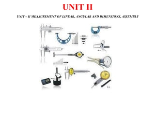
  • 1. UNIT II UNIT – II MEASUREMENT OF LINEAR, ANGULAR AND DIMENSIONS, ASSEMBLY
  • 2. Mr.P.Prakash,M.E, AP/Mech , AP Syllabus Linear Measuring Classification Instruments – Evolution - Types – Limit gauges – gauge design – terminology – procedure Concepts of interchange ability and selective assembly Angular measuring instruments – Types – Bevel protractor - clinometers angle gauges - Spirit levels sine bar, Angle alignment telescope – Autocollimator –Applications.
  • 3. Mr.P.Prakash,M.E, AP/Mech , AP • Common measurement is dimensions of anobject. • Types of measuring instruments, 1. Low Resolution Devices (Up to 0.25mm) 1. Steel rule alone 2. Steel rule with the assistance of (i) Calipers, (ii) Dividers and (iii) surface gauges 3. Thickness gauges 2. Medium Resolution Devices (Upto 0.0025mm) I. Micrometers alone. 2. Micrometers with assistance of (i) telescoping & (ii) extensible ball gauges 3. Vernier 4. Dial indicators 5. Measuring microscope 3. High Resolution Devices (Less than microns) 1. Gauge blocks alone 2. Comparators (iv) Optical flats
  • 4. LINEAR MEASURING INSTRUMENTS 4 - Includes the measurement of lengths, diameters, heights and thickness. - Comparison with standard dimensions. • Devices used for measuring the linear measurementsare, (i) Vernier calipers (ii) Micrometers (iii) Slip gauge or gauge blacks (iv) Comparators
  • 5. LINEAR MEASURING INSTRUMENTS 5 a. Line Measurement – measurement of distance between two points of a line. Ex: Steel Rule b. End Measurement - measurement of distance betweentwo surfaces. Ex: micrometer
  • 6. LINEAR MEASURING INSTRUMENTS 6 1. Steel Rule 2. Calipers, Dividers with combination of steelrule 3. Dial indicators 4. Micrometers 5. Slip gauges 6. Comparators
  • 8. 8
  • 9. 9 One small division on main scale = 1 mm No. of divisions on Vernier scale = 50 50 Vernier scale divisions = 49 divisions on main scale (or 49 mm) Each division on Vernier scale = (49/50) mm Least Count = One main scale division - One Vernier scale division = 1 - (49/50) mm = (50 - 49)/50 = (1/50) mm Least Count of Vernier = = 0.02 mm
  • 10. a. TYPE-A VERNIER CALIPER 10
  • 11. b. TYPE-B VERNIER CALIPER 11
  • 12. c. TYPE-C VERNIER CALIPER 12
  • 13. • Errors in measurements with Vernier Caliper:  Errors may arise in manipulation of vernier caliper  Jaw movement should be perpendicular to scale reading.  Contact portion of measuring jaws should be good conditions. also when we close the jaws, it should be tightly together. • Care and precautions in use of Vernier Calipers: 1. The jaws should not be used as a hammer because vernier caliper is not a strong instrument. 2. Instruments should be kept in box and not suddenly dropped and turned up and down. 3. Should not be used with oil, grit and chips in part to be measured. 4. One hand of operator should be used for stationary jaw and the other hand for supporting the movable jaw while measuring. 5. The operator should wear eye-glass and magnifying glass during measurement because the accuracy of measurement mainly depends on the sensing of sight and sense of touch. 13
  • 14. 2. VERNIER HEIGHT GAUGE 14
  • 15. 3. VERNIER DEPTH GAUGE 15
  • 17. 17 4. MASTER DIAL INDICATOR VERNIER CALIPER • Combination of vernier caliper & dial gauge • For internal & external measurements. 5. COMBINATION OF DEPTH & ANGLE GAGUE • Looks like protractor • Used to measure both angle & depth 6. DIGITAL LENGTH GAGUES • Indicated in digital display while measuring • Before measuring set to zero
  • 19. TYPES OF MICROMETER 19 1. OutsideMicrometer 2. InsideMicrometer 3. StickMicrometer 4. Micrometer DepthGauge 5. ThreadMicrometer 6. V-Anvil MicrometerCaliper 7. BladeTypeMicrometer 8. Micrometer For Measuring Thickness Of Cylindrical Walls 9. Dial Micrometer Caliper 10.Bench Micrometer 11.Taper-screw Operated Internal Micrometer 12.Groove Micrometer 13.Digital Micrometer 14.Differential Screw Micrometer
  • 20. 1. OUTSIDE MICROMETER 20 Pitch of the Barrel = 0.5 mm Thimble graduation = 50 mm So LC = 0.01 mm
  • 21. 2. INSIDE MICROMETER 21 •Used to measure Inner Diameter. •4 Parts – Measuring Heads, Extension Rods, Spacing Collars, Handles. •Used to measure cylinder Diameter, rings. •Ranges of IMM 25-150, 150-300, 300-450, 450-600mm.
  • 22. 3. STICK MICROMETER 22 •Used to measure larger length. •For maximum range of measurement. •Accuracy of stick MM is +0.005 mm or – 0.005mm.
  • 23. 4. MICROMETER DEPTH GAUGE 23 •Used to measure depth of holes, slots. •Can side up & down & perpendicular to axis ofhole. •Range of depth MM is 0 – 225 mm. •Length of extension rod equal to range of micrometer.
  • 24. 24 5. THREAD MICROMETER •To measure threads within range of threadpitches.
  • 25. 25 6. V- ANVIL MICROMETER CALIPER •Range of error is checked by V-anvil MM in grinding & other spl m/c. •Accuracy is high because all parts in this caliper are precise. .
  • 26. 26 7. BLADE TYPE MICROMETER •Used for circular formed tools, diameters of narrow grooves, slots & keyways. •Rate of measurement is fast.
  • 27. 8. MICROMETER FOR MEASURING THICKNESS OF CYLINDRICAL WALLS •Its difficult to measure OD of cylinder walls. •Anvil is in cylindrical form & spindle is perpendicular to spherical surface. 27
  • 28. 9. DIAL MICROMETER CALIPER •Dial indicator is connected with movable anvil. •Anvil movement is indicated on dial indicator. •Its useful for statistical quantity for all different sizeof variation. 28
  • 29. 29 10. BENCH MICROMETER •All parts are mounted on bench. •Fixed anvil in one end and Movable anvil with dial with other end Ex: Floating Carriage Micrometer
  • 30. 30 11. TAPER-SCREW OPERATED INTERNAL MICROMETER •Taper screw is fixed with end of main spindle. •Ratchet is revolved, vibration is adjusted in bore and can be felt by feeler.
  • 31. 12. GROOVE MICROMETER •Used to measure grooves which are locatedcentrally. •MM are satin-chrome finished for highprecision. •Used to measure the distance between edge toland. 31
  • 32. 13. DIGITAL MICROMETER •Digital is as numerical. •Interpolation can be avoided. •Accuracy is higher than analog type. •Spindle can be located at desired position & adjustment of spindle is easy. 32
  • 33. 14. DIFFERENTIAL SCREW MICROMETER •A differential screw is a mechanism used for making small, precise adjustments to thespacing between two a microscope). objects (such as in focusing •Designed to get differential movement •Two pitches of 1.25mm & 1.00mm •Thimble division is 100 •Main spindle advancement conventional type is larger than •Higher degree of accuracy & ranges 0.0002mm 33
  • 35. COMPARATOR An instrument, which provides the measurement in terms of comparison, is called a comparator. A comparator works on relative measurement. Comparators are generally used for linear measurements. A comparator has to be set to a reference value (usually zero setting) by employing a standard. Once it is set to this reference value, all subsequent readings indicate the deviation from the standard. The variation in the measured value may be in terms of change in displacement, pressure, fluid flow, temperature, and so on. 35
  • 36. TYPES OF COMPARATOR 1. Mechanicalcomparators a. Dial Indicator b. ReedtypeMechanicalComparator 2. Electricalcomparators(Electro-mechanicalcomparators) 3. Electroniccomparators 4. FluidDisplacementcomparators 5. Pneumaticcomparators a. FreeFlowType/VelocityTypePneumaticcomparators b. BackPressurePneumaticcomparators i. Solex Air Gauge ii. DifferentialComparators 6. Multi-checkcomparators 7. Opticalcomparators 36
  • 37. 37 MECHANICAL COMPARATOR a. DIAL INDICATOR •It is primarily used to compare workpieces against a master. •It consists of a body with a circular graduated dial, a contact point connected to a gear train and an indicating hand, which directly indicates the linear displacement of the contact point.
  • 40. b. REED TYPE MECHANICAL COMPARATOR 40
  • 42.  Electrical comparators generally depend on a Wheatstone bridge circuit for measurement.  The plunger is the sensing element, the movement of which displaces an armature inside a pair of coils. Movement of the armature causes change in inductance in the two coils, resulting in a net change in inductance.  This change causes imbalance in the bridge circuit, resulting in an output.  Least count of the electrical comparator is 0.001mm Ex: Linear Variable Differential Transformer (LVDT) Advantages 1.Very less number of moving parts 2.High magnification 3.Pointer is very light and not sensitive to vibrations Disadvantages 1.It is more expensive than the mechanical comparator 2.Heating of coils in the measuring unit may cause zero drift and alter the calibration 43
  • 43. 43 3. ELECTRONIC COMPARATORS  The movement at the probe tip actuates inductance transducer which is supplied with an a.c. source from the oscillator.  The transducer converts this movement into an electrical signal which is then amplified and fed via an oscillator to the demodulator.  The current in D.C. form, then passes to the meter and the probe tip movement is displayed as a linear measurement over a circular scale.
  • 45. ADVANTAGES OF ELECTRONIC COMPARATORS 1. High accuracy and reliability 2. High sensitivity in all ranges 3. High speed of response 4. Easy provision for multiple amplification ranges 5. Versatility (a large number of measurement situations can be handled with standard accessories) 6. Easy integration into an automated system 45
  • 46. 4. FLUID DISPLACEMENT COMPARATOR  A capillary tube is used along with a graduated scale attached to it and it is filled with the low viscosity fluid.  At the bottom of the fluid chamber, there is a diaphragm is arranged.  A plunger is attached at the bottom of the diaphragm.  This plunger captures the deflection and transmits to the diaphragm.  When the workpiece is contacted with the plunger the deflection will be transmitted to the diaphragm.  The diaphragm will get deflected and a small rise in liquid level in the capillary tube occurs.  This will be measured with the help of the scale attached to the capillary tube.  When the workpiece removed from contact with the plunger the diaphragm will get its original position. 46
  • 47. 5. PNEUMATIC COMPARATORS (Pneumatic Gauge) 1. FLOW / VELOCITY TYPE 47
  • 48. 2. PRESSURE TYPE a. SOLEX AIR GAUGE 48
  • 49. 2. PRESSURE TYPE 49 b. DIFFERENTIAL COMPARATOR
  • 50. ADVANTAGES AND DISADVANTAGES OF PNEUMATIC COMPARATORS Advantages 1. The operation is very simple and low price 2. Indicating & measuring is done at two different places 3. The gauging members are direct contact with the work Disadvantages 1.These comparators are very sensitive are temperature and humidity. 2.For different job, it requires different gauging heads 50
  • 51. 6. MULTI-CHECK COMPARATOR In multi check comparators, the following classifications are used. 1.Electrical 2.Air 3.Combination air-electric. Electric multi-checks: In this method, about twenty or more electrical check heads are combined to measure the number of dimensions of same part simultaneously. Air multi-checks: Group of pneumatic comparators are set with more numbers to measure more number of dimensions simultaneously. An air electric multi-check: Air comparator and electric-checks are combined used to measure more than one dimensions. Automatic gauging machines: Thesemachinesincorporate comparator-amplifyingmethods. 51
  • 52. 52 ADVANTAGES OF MULTI CHECK COMPARATORS 1. Theinstrumentisusedforhighproductionchecking. 2. Errorsindimensionareveryless. 3. It savestimeformeasuringdimensions. 4. It eliminatesmanualinspection. 5. It segregates andclassifiesautomatically.
  • 55. 2 DIFFERENCE BETWEEN GAUGES AND MEASURING INSTRUMENTS
  • 56. GAUGE BLOCKS 3 • Fixed Gauges are used for checking the size, shape without a scale being used to check dimensions, and form. Example of fixed gauges: 1. Block Gauges (Slip Gauges) 2. Limit Gauges (Plug Gauges) 3. Angle Gauges 4. Mating Gauges (Feeler, Radius, Thread Pitch Gauges)
  • 57. 1. SLIP GAUGES or GAUGE BLOCKS 4 These are small blocks of alloy steel. Used in the manufacturing shops as length standards. Not to be used for regular and continuous measurement. Rectangular blocks with thickness representing the dimension of the block. The measuring surfaces of the gauge blocks are finished to a very high degree of finish, flatness and accuracy. Come in sets with different number of pieces and a typical set consisting of 88 pieces for metric units.
  • 58. TYPES OF SLIP GAUGES 5 Grade II : Workshop grade for rough checks. Grade I : Used for setting up sine bars, checking gap gauges and setting dial test indicators to zero. Grade 0 : Used in tool room and inspection department. Grade 00 : Kept in standard room and used for high precision work such as checking Grade I and Grade II slip gauges.
  • 59. SLIP GAUGES • Wringing is defined as the property of the measuring faces of slip gauges to adhere to the measuring faces of other slip gauges. • Wringing is nothing, but removing the atmospheric air between two mating surfaces of any two gauge blocks, so that the blocks stick to each other due to vacuum. • Due to do this, hold the two blocks edge-to -edge, and gently push one of the blocks inside so as to make it sit on the other block, completely. 6
  • 60. MANUFACTURE OF SLIP GAUGES The following additional operations are carried out, 1. Approximate size of slip gauges is done by preliminary operations 2. Blocks are hardened & wear resistant by a special heat treatment process 3. Tostabilize the life of the block, seasoning is done 4. The approximate required dimension is done by final grinding process 5. Toget the exact size of slip gauges, lapping operation is done 6. Comparison is made with grand master sets CALIBRATION OF SLIP GAUGES Comparators are used to calibrate the slip gauges 7
  • 62. LIMIT GAUGES • These are also called “GO” and “NO GO” gauges refers to an inspection tool used to check a workpiece against its allowed tolerances. • To check the accuracy of a hole, a cylindrical bar with highly finished ends of different diameters is used. • Its name derives from its use: the gauge has two tests; the check involves the workpiece having to pass one test (Go) and fail the other (No Go). • It is an integral part of the quality process that is used in the manufacturing industry to ensure interchangeability of parts between processes, or even between different manufacturers. 9
  • 63. TYPES of LIMIT GAUGES 1. Plug gauges a. Double ended Plug gauges b. Progressive type of Plug gauges 2. Taper Plug Gauge a. Taper plug gauge - Plain b. Taper plug gauge – tanged 3. Ring Gauges a. Taper ring gauge - Plain b. Taper ring gauge – tanged 4. Combined Limit Gauges 5. Position Gauges 6. Snap gauges a. Double ended Snap gauges b. Progressive type of Snap gauges c. Adjustable Snap gauges d. Plate type Double ended Snap gauges e. Plate type single ended Snap gauges 10
  • 64. 1. PLUG GAUGES  The ends are hardened and accurately finished by grinding. One end is the GO end and the other end is NOGO end.  Usually, the GO end will be equal to the lower limit size of the hole and the NOGO end will be equal to the upper limit size of the hole.  If the size of the hole is within the limits, the GO end should go inside the hole and NOGO end should not go.  If the GO end and does not go, the hole is under size and also if NOGO end goes, the hole is over size.  Hence, the components are rejected in 11 both the cases.
  • 67. 13 a. Double ended Plug gauges b. Progressive type of Plug gauges
  • 68. 2. TAPER PLUG GAUGE • It is used to check the taper. It is also used to measure the diameter of the taper at some point. 14
  • 69. a. Taper plug gauge - Plain b. Taper plug gauge – Tanged 15
  • 70. 16 3. RING GAUGES  Ring gauges are mainly used for checking the diameter of shafts having a central hole.  The hole is accurately finished by grinding and lapping after taking hardening process.  The periphery of the ring is knurled to give more grips while handling the gauges.  We have to make two ring gauges separately to check the shaft such as GO ring gauge and NOGO ring gauge.  But the hole of GO ring gauge is made to the upper limit size of the shaft and NOGO for the lower limit.  While checking the shaft, the GO ring gauge will pass through the shaft and NOGO will not pass.  To identify the NOGO ring gauges easily, a red mark or a small groove cut on its periphery.
  • 71. 17
  • 72. 18 a. Taper ring gauge - Plain b. Taper Ring Gauge – Tanged
  • 73. 19 4. SNAP GAUGES a. Double ended Snap gauges • It is used for checking external diameters. Shafts are mainly checked by the snap gauges.
  • 74. 20 b. Progressive type of Snap gauges
  • 76. d. Plate type single ended Snap gauges 22
  • 77. e. Plate type Double ended Snap gauges 23
  • 78. 24 5. COMBINED LIMIT GAUGES In case of gauging of cylindrical holes, it is impossible to combine both the 'Go' and 'No Go' dimensions of plug gauge and thus a single gauge doing the work of checking both the upper and lower limits
  • 79. 25 6. POSITION GAUGES It is designed for checking the position of features in relation to another surface. Ex: Contour gauges, receiver gauges, profile gauges etc.
  • 81. 4. MATING GAUGES According to the measurement of parameters involved, the gauges are classified into, 1. Thread Gauges 2. Form Gauges 3. Screw Pitch Gauges 4. Radius & Fillet Gauges 5. Feeler Gauges 6. Plate Gauges & Wire Gauges 7. Indication Gauges 8. Air Gauges 27
  • 85. 4. RADIUS & FILLET GAUGES 31
  • 87. 6. PLATE GAUGES & WIRE GAUGES 33
  • 88. 7. INDICATING GAUGES • Indicating gauges employ a means to magnify how much a dimension deviates, plus or minus, from a given standard to which the gauge has been set. 34
  • 89. 35 8. AIR GAUGES / AIR-OPERATED GAUGES • Pneumatic or air gauges are used primarily to determine the inside characteristics of a hole by means of compressed air.
  • 90. 36 INTERCHANGEABILITY & SELECTIVE ASSEMBLY What is interchangeability?  An interchangeable part is one which can be substituted for similar part manufactured to the same drawing.  When one component assembles properly (and which satisfies the functionality aspect of the assembly) with any mating component, both chosen at random, then it is known as interchangeability.
  • 91. 37 TYPES OF INTERCHANGEABILITY & SELECTIVE ASSEMBLY i. Universal interchangeability: When the parts that are manufactured at different locations are randomly chosen for assembly, it is known as universal interchangeability.” Ex. International standards ii. Local interchangeability: “When the parts that are manufactured at the same manufacturing unit are randomly drawn for assembly, it is referred to as local interchangeability. Ex. Local standards
  • 92. 38 SELECTIVE ASSEMBLY • In selective assembly, the parts are graded according to the size and only matched grades of mating parts are assembled. • This technique is most suitable where close fit of two components assembled is required. • Selective assembly provides complete protection against non- conforming assemblies and reduces machining costs as close tolerances can be maintained. • Suppose some parts (shafts & holes) are manufactured to a tolerance of 0.01 mm, then an automatic gauge can separate them into ten different groups of 0.001 mm limit for selective assembly of the individual parts. Thus high quality and low cost can be achieved. • Selective assembly is used in aircraft, automobile industries where tolerances are very narrow and not possible to manufacture at reasonable costs
  • 93. ADVANTAGES OF INTERCHANGEABILITY  The assembly of mating parts is easier. Since any component picked up from its lot will assemble with any other mating part from another lot without additional fitting and machining.  It enhances the production rate.  It brings down the assembling cost drastically.  Repairing of existing machines or products is simplified because component parts can be easily replaced.  Replacement of worn out parts is easy.  Without interchangeability mass production is not possible. 39
  • 95. • Angle is defined as the opening between the two lines meet at a point. • If a angle is divided into 360 parts, each part is called as degree (ᵒ) • Each degree is divided into 60 parts and each that part is called minute (‘). • Each second have 60 parts and each that part is called second (“). 2 ANGLE MEASUREMENT - INTRODUCTION
  • 96. Face Standard Angular Measuring Devices Sine Bar Line Standard Angular Measuring Devices Protractor Universal Bevel Protractor Angle Gauges Measurement of Inclines Clinometers Spirit Level Angle Comparators Auto Collimator Angle Dekkor Alignment Telescope 3 INSTRUMENTS USED FOR ANGULAR MEASUREMENT
  • 97. 4 • It is a precision measuring instrument and is an excellent example of combination of linear measurement and angular measurement when used in conjunction with gauge blocks (slip gauges). • Sine bar is made of high carbon, high chromium corrosion resistant steel, suitably hardened, precision ground and stabilised. • It consists of a bar carrying a suitable pair of rollers set a known centre distance. • Relief holes are provided for easy handling of sine bar and for reducing the weight of the sine bar. 1. FACE STANDARD ANGULAR MEASURING DEVICES - SINE BAR
  • 98. WORKING PRINCIPLE OF SINE BAR 5 • The principle of operation of sine bar is relay upon the application of trigonometry. • The sine bar is placed on the surface plate with the slip gauges of the required length (H) under one roller and opposite to the angle ϴ as shown in figure. The angle ϴ is given by, Taper Angle, tan = h / L in Degrees h = Height of the Slip Gauge in mm. L = Length between two rollers in mm
  • 99. USE OF SINE BAR 6 1. Checking unknown angles of small components:  When an angle of component to be compared is unknown, it is necessarily first find out the approximate taper angle with the help of bevel protector.  If the angle is ϴ, then the sine bar is set at an angle ϴ with the help of slipgauges and clamped to an angle plate as shown in figure.  A dial indicator is set at a one end of the work and moved to the other end and the deviation is note down.  Again slip gauges are so adjusted (according to the deviation) such that dial indicator reads zero as it move from one end to other end of the work piece.  If the deviation is noted down by the dial indicator .
  • 100. 2. For locating any work to a given angle  For this, assume surface plate is perfectly flat, so that its surface is perfectly horizontal.  One roller of the sine bar is placed on the surface plate and the other is placed on the slip gauge rack of height H.  Let the sine bar is set to an angle ϴ. Sine Ө = h/L  where L is the distance between the center.  Thus knowing ϴ, H can be found and any work can be set out at this angle as the top face of the sine bar is inclined at angle ϴ to the surface plate.  For better result both rollers must placed on slip gauge of height h1 and h2 respectively. 7
  • 101. 8 3. Checking of unknown angles of heavy component:  When components are heavy and cannot be mounted on the sine bar, the sine bar is mounted on the component as shown in figure.  The height over the rollers can be measured by a Vernier height gauge using a dial gauge mounted on the anvil of it.  The difference in the two readings of height gauge divided by the centre distance of sine bar gives the sine angle of the component to be measured.
  • 102. HEIGHT GAUGE TOOLS NEEDED 9 SURFACE GROUND GRANITE TABLE GAUGE BLOCKS
  • 103. Accuracy requirements of a sine bar: The accuracy of sine bar depends on the following constructional features:  The rollers must have equal diameters and equal cylinders.  The rollers should be placed parallel to each other and also to the upperface.  The accurate length of center to center of rollers must beknown.  The top surface of the bar must be flat with high degree of accuracy. Classification of sine bars: Generally, sine bars are classified into two categories: 1. According to the accuracy of center distance a. Grade A - These sine bars are more accurate up to 0.01mm of length. b. Grade B - These sine bars are accurate up to 0.02 mm of length. 2. According to the availability of different designs a. Type 1 b. Type 2 c. Type 3 d. Type 4 10
  • 104. 2. According to the availability of different designs: a. Type 1 Sine Bar : It is the most commonly used type. In this type, the rollers are arranged in such a way that their outside surfaces on one side is level with the plane top surface of the sine bar. 11
  • 105. b. Type 2 Sine Bar 12 In this type 2, a sine bar with hollow rollers which outside diameter is equal to the width of sine bar. This type is very much useful in instances where the width of the bar enters into calculation of work.
  • 106. c. Type 3 Sine Bar A sine bar with pins on both sides is used where the ordinary sine bar cannot be used on the top surface due to interruption. 13
  • 107. d. Type 4 Sine Bar Generally preferred where the distance between the rollers can be adjusted exactly. 14
  • 108. MODIFICATIONS IN SINE BAR 15 Sine bars are modified into two forms such as, 1. Sine Table 2. Sine Center
  • 109. MODIFICATIONS IN SINE BAR 16 1. Sine Table
  • 110. MODIFICATIONS IN SINE BAR 2. Sine Center  In sine center we can easily mount the conical work pieces as compared to sine bar.  In which one roller is hinged and mounted on its own datum surface.  The top surface of the bar is provided with a pair of clamps and center for holding the work. 17
  • 111. 18 • Advantages of sine bar 1. It is precise and accurate angle measuring device. 2. It is simple in design and construction. 3. It is easily available • Disadvantages 1. It is not fairly reliable at angles less than 15 but become increasingly inaccurate as the angle increases. It is impractical to use sine bar for angle above 45 . 2. It is difficult to handle and position the slip gauges. 3. The sine bar is physically clumsy to hold in position. 4. The application is limited for a fixed center distance between two rollers. 5. Slight errors of the sine bar cause larger angular errors. ADVANTAGES AND DISADVANTAGES OF SINE BARS
  • 112. 19 SOURCES OF ERROR IN SINE BARS The different sources of errors are listed below: • Error in distance between roller centers. • Error in slip gauge combination. • Error in checking of parallelism. • Error in equality of size of rollers and cylindricity. • Error in parallelism of roller axes with each other. • Error in flatness of the upper surface of sine bar
  • 113. 20 • A simple Protractor is the basic device for measuring angles. • Like a steel rule, the simple protractor has limited usage in engineering metrology. • Bevel protractors is a type of protractor which is used as an angular measuring instruments. • Types of bevel protractors: 1. Vernier Bevel Protractor or Universal Protractor 2. Optical Protractor 2. LINE STANDARD ANGULAR MEASURING DEVICES – PROTRACTOR
  • 114. 1. Vernier or Universal Bevel Protractor 21  It has a base plate or stock whose surface has a high degree of flatness and surface finish and it is placed on the workpiece whose angle is to be measured.  An adjustable blade attached to a circular dial is made to coincide with the angular surface.  It can be swiveled to the required angle and locked into position to facilitate accurate reading of the circular scale that is mounted on the dial.  The main scale on the dial is graduated in degrees and rotates with the rotation of the adjustable blade.  A stationary vernier scale mounted close to the dial, enables measurements to a least count of 5‘ or less.  An acute angle attachment is provided for the measurement of acute angles.
  • 115. 1. Vernier or Universal Bevel Protractor 22 • The main scale on the dial is divided into four quadrants, each measuring 90°. Each division on this scale reads 1°. • The Vernier scale has 12 Divisions each side of the centre zero. • These are marked 0-60 minutes of arc, so that each division equals 1/12 of 60, that is 5 minutes of arc.
  • 116. 2. Optical Bevel Protractor 23 •A recent development of Vernier bevel protector is optical bevel protector. •In this instrument, a circular glass plate is divided at 10 minutes intervals throughout the whole 360º are fitted inside the main body. •A small microscope is fitted through which the circular graduations can be viewed. •The readings are taken against a Vernier scale with the help of a microscope. • With the help of microscope it is possible to read about 2 minutes.
  • 117. APPLICATIONS OF BEVEL PROTRACTOR 1. For checking a ‘V’ block 2. For measuring acute angle 3. For checking inside beveled face of a ground surface 24
  • 118. 25
  • 119. 3. ANGLE GAUGES 26 • Angle gauges are made of hardened steel and seasoned carefully to ensure permanence of angular accuracy, and the measuring faces are lapped and polished to a high degree of accuracy and flatness like slip gauges.
  • 120. 4. MEASUREMENT OF INCLINES Inclination of a surface generally represents its deviation from the horizontal or vertical planes. Gravitational principle can be used in construction of measurements of such inclinations. Examples: 1. Spirit Level 2. Clinometer 27
  • 121. SPIRIT LEVEL  Commonly used to inspect the horizontal position of surfaces.  It essentially consists of a closed glass tube of accurate form and is called as the vial.  It is filled with a low viscosity liquid such as ether, alcohol or benzol, leaving a small space for the formation of an air or gas bubble. 28
  • 122. SPIRIT LEVEL  The liquid due to its greater specific weight tends to fill the lower portion of the closed space.  The upper side of the vial is graduated in linear units.  Inclination of a surface can be known from the deviation of the bubble from its position when the spirit level is kept in a horizontal plane.  An angular value is assigned to the vial when the distance moved by the bubble from the zero will correspond the angle directly.  Temperature variations in the ambient condition cause both liquid and vial to expand or contract. Therefore, selection of proper liquid and material for the spirit level is very important for accurate result.  To reduce the effect of heat transfer in handling spirit levels are made with thermally insulated handles. 29
  • 123. CLINOMETER 30 3 0  A Clinometer is a special case of the application of spirit level.  In Clinometer, the spirit level is mounted on a rotary member carried in a housing.  One face of the housing forms the base of the instrument. On the housing, there is a circular scale.  The Clinometer is first placed on one face of the workpiece and the rotary member is adjusted till the bubble is exactly at the center of the spirit level. The angle is noted on the scale.  A second reading is taken in a similar manner on the second face of the workpiece.  The included angle is then the difference between the two readings.
  • 124. 5. ANGLE COMPARATORS 31  Angle comparators are the metrological instruments used for finding the difference between two nearly equal angles.  The principle used in angle comparators is same as that of linear comparators. Ex: 1. Autocollimators 2. Angle Dekkor 3. Alignment Telescope
  • 126. WORKING OF AUTOCOLLIMATOR  Auto-collimator is an optical instrument used for the measurement of small angular differences, changes or deflection, plane surface inspection etc.  For small angular measurements, autocollimator provides a very sensitive and accurate approach.  If a light source is placed in the flows of a collimating lens, it is rejected as a parallel beam of light.  If this beam is made to strike a plane reflector, kept normal to the optical axis, it is reflected back along its own path and is brought to the same focus.  If the reflector is tilted through a small angle ‘ ’. Then the parallel beam is deflected twice the angle and is brought to focus in the same plane as the light source.  The distance of focus from the object is given by, x = 2 .f Where, f = Focul length of the lens = Tilted angle of reflecting mirror/plane
  • 127. APPLICATIONS OF AUTOCOLLIMATOR 1) Measuring the difference in height of length standards. 2) Checking the flatness and straightness of surfaces. 3) Checking squareness of two surfaces. 4) Checking alignment or parallelism. 5) Comparative measurement using master angles. 6) For machine tool adjustment testing.
  • 129. ANGLE DEKKOR • This is also a type of auto-collimator. • This instrument is essentially used as a comparator and measures the change in angular position of the reflector in two planes. • It has an illuminated scale, which receives light directed through a prism. • The light beam carrying the image of the illuminated scale passes through the collimating lens and falls onto the reflecting surface of the workpiece. • After getting reflected from the workpiece, it is refocused by the lens in field view of the eyepiece. • While doing so, the image of the illuminated scale would have undergone a rotation of 90° with respect to the optical axis. • Now, the light beam will pass through the datum scale fixed across the path of the light beam. • When viewed through the eyepiece, the reading on the illuminated scale measures angular deviations from one axis at 90° to the optical axis, and the reading on the fixed datum scale measures the deviation about an axis mutually perpendicular to this. 36
  • 130. APPLICATIONS OF ANGLE DEKKOR 1. Measurement of sloping angle of V-blocks 2. Calibration of taper gauges 3. Measurement of angles of conical parts 4. Measurement of angles of work part surfaces, which are simultaneously inclined in two planes 5. Determination of a precise angular setting for machining operations, for example, milling a slot at some precise angle to a previously machined datum surface.
  • 131. ALIGNMENT TELESCOPE  Alignment telescope is used for aligning of bores, surfaces and check squareness, straightness, flatness, parallelism, vertically and level.  One of the important type of alignment telescope is Taylor-Hobson alignment telescope.  The telescope has an internal-focusing optical system, similar in principle to that of the surveyor’ s level built into a robust unit having a precisely ground external diameter.  The focusing knob can be clearly seen in the optical system is shown in fig.  The collimating unit consists of another steel tube, ground to the same diameter as the telescope and containing an illuminating system, a graticule G a collimating lens and another graticule G.  The graticule G is graduated with central cross lines, surrounded with scales and concentric circles and lies exactly at the principal focus of the collimating lenses.  The graticule G contains a central pattern of converging V and several graduated scales lying in two directions at right angles. 38