1. Computer Graphics Lecture 2
1
Video Display Devices
The display devices are known as output devices. The most commonly used
output device in a graphics video monitor. The operations of most video monitors are
based on the standard cathode-ray-tube (CRT) design.
How the Interactive Graphics display works
The modern graphics display is extremely simple in construction.
It consists of three components:
1- A digital memory, or frame buffer, in which the displayed Image is stored as a matrix
of intensity values.
2- A monitor
3- A display controller, which is a simple interface that passes the contents of the frame
buffer to the monitor. Inside the frame buffer the image is stored as a pattern of binary
digital numbers, which represent a rectangular array of picture elements, or pixel.
The pixel is the smallest addressable screen element. In the Simplest case where we
wish to store only black and white images, we can represent black pixels by 0's in the
frame buffer and white Pixels by 1's. The display controller simply reads each successive
byte of data from the frame buffer and converts each 0 and 1 to the corresponding
video signal. This signal is then fed to the monitor. If we wish to change the displayed
picture all we need to do is to change of modify the frame buffer contents to represent
the new pattern of pixels.
Cathode-Ray-Tubes
A CRT is an evacuated glass tube. An electron gun at the rear of the tube
produces a beam of electrons which is directed towards the front of the tube (screen).
The inner side of the screen is coated with phosphor substance which gives off light
when it is stroked by electrons. It is possible to control the point at which the electron
beam strikes the screen, and therefore the position of the dot upon the screen, by
deflecting the electron beam. The fig below shows the electrostatic deflection of the
electron beam in a CRT.
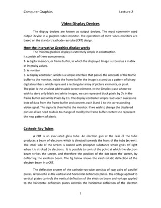
The deflection system of the cathode-ray-tube consists of two pairs of parallel
plates, referred to as the vertical and horizontal deflection plates. The voltage applied to
vertical plates controls the vertical deflection of the electron beam and voltage applied
to the horizontal deflection plates controls the horizontal deflection of the electron
2. Computer Graphics Lecture 2
2
beam. There are two techniques used for producing image on the CRT screen: Vector
scan / random scan and Raster scan.
Vector Scan / Random Scan Display
As shown in fig, vector scan CRT display directly traces out only the desired lines on CRT
i.e. If we want a line connecting point A with point B on the vector graphics display, we
simply drive the beam deflection circuitry, which will cause beam to go directly from
point A to B. if we want to move the beam from point A to point B without showing a
line between points, we can blank the beam as we move it. To move the beam across
A
B
3. Computer Graphics Lecture 2
3
CRT, the information about, magnitude and direction is required. This information is
generated with the help of vector graphics generator.
The figure bellow shows the typical vector display architecture. It consists of
display controller, central processing unit (CPU), display buffer memory and a CRT. A
display controller is connected as an I/O peripheral to the central processing unit. The
display buffer memory stores the computer produced display list or display program.
The program contains point and line plotting commands with (x,y) or (x,y,z) end point
co-ordinates, as well as character plotting commands. The display controller interprets
commands for plotting points, lines and characters and sends digital and point
coordinates to a vector generator. The vector generator then converts the digital co-
ordinate values to analog voltages for beam-deflection circuits that displace an electron
beam writing on CRT’s phosphor coating.
Display buffer memory
In vector display beam is deflected from end point to end point, hence this technique is
also called random scan. We know as beam, strikes phosphor it emits light. But
phosphor light decays after few milliseconds and therefore it is necessary to repeat
through the display list to refresh the phosphor at least 30 times per second to avoid
(Interaction data)
CUP
I/O Port
(Display
commands)
CRT
.
Move
100
300
LINE
400
300
CHAR
CAR
MOVE
100
100
LINE
.
.
JMP
Display controller
Keyboard Mouse
4. Computer Graphics Lecture 2
4
flicker. As display buffer is used to store display list and it is used for refreshing, the
display buffer memory is also called refresh buffer.
Raster Scan Display
The Figure below shows the architecture of a raster display. It consists of display
controller, central processing unit (CPU), video controller, refresh buffer, keyboard,
mouse and the CRT.
As shown in the fig below the display image is stored in the form of 1s and 0s in the
refresh buffer. The video controller reads this refresh buffer and produces the actual
image on the screen. It does this by scanning one scan line at a time, from top to bottom
and then back to the top.
(Interaction data) (Display commands)
Refresh buffer
00000000000000000000
00000001111110000000
00000001111110000000
00000000011000000000
00000000011000000000
CPU
I/O port
Display controller
Video controller
Keyboard
Mouse
T
5. Computer Graphics Lecture 2
5
Raster scan is the most common method of displaying images on the CRT screen.
In this method, the horizontal and vertical deflection signals are generated to move the
beam all over the screen in a pattern.
Here, the beam is swept back and forth from the left to the right across the
screen. When the beam is moved from the left to the right, it is ON. The beam is OFF,
when it is moved from the right to the left.
When the beam reaches the bottom of the screen, it is made OFF and rapidly
retraced back to the top left to start again. A display produced in this way is called raster
scan display.
In raster scan displays a special area of memory is dedicated to graphics only.
This memory area is called frame buffer. It holds the set of intensity values for all the
screen points. The stored intensity values are retrieved from frame buffer and displayed
on the screen one row (scan line) at a time. Each screen point is referred to as a pixel.
Each pixel on the screen can be specified by its row and column number. Thus by
specifying row and column number we can specify the pixel position on the screen.
Intensity range for pixel positions depends on the capability of the raster system.
It can be a simple black and white system or color system. In a simple black and white
system, each pixel position is either on or off, so only one bit per pixel is needed to
control the intensity of the pixel positions. Additional bits are required when color and
intensity variations can be displayed. Up to 24 bits per pixel are included in high quality
display systems, which can require several megabytes of storage space for the frame
buffer. On a black and white system with one bit per pixel, the frame buffer is called a
bitmap. For systems with multiple bits per pixel, the frame buffer is often referred to as
a pixmap.
Vector Scan Display Raster Scan Display
1. In vector scan display the beam is
moved between the end points of
the graphics primitives.
In raster scan display the beam is moved
all over the screen one scan line at a
time, from top to bottom and then back
to top.
2. Vector display flickers when the
number of primitives in the buffer
becomes too large.
In raster display, the refresh process is
independent of the complexity of the
image.
3. Scan conversion is not required. Graphics primitives are specified in terms
of their endpoints and must be scan
6. Computer Graphics Lecture 2
6
converted into their corresponding pixels
in the frame buffer.
4. Scan conversion hardware is not
required.
Because each primitive must be scan-
converted, real time dynamics is far
more computational and requires
separate scan conversion hardware.
5. Vector display draws continuous
and smooth lines.
Raster display can display
mathematically smooth lines, polygons,
and boundaries of curved primitives only
by approximating them with pixels on
the raster grid.
6. Cost is more. Cost is low.
7. Vector display only draws line
characters.
Raster display has ability to display areas
filled with solid colors or patterns.
Important Characteristics of Video Display Devices
Persistence: The major difference between phosphors is their persistence. It decides
how long they continue to emit light after the electron beam is removed. Persistence is
defined as the time it takes the emitted light from the screen to decay to one-tenth of
its original intensity. Lower persistence phosphors require higher refreshing rates to
maintain a picture on the screen without flicker. However it is useful for displaying
animations. On the other hand higher persistence phosphors are useful for displaying
static and highly complex pictures.
Resolution: Resolution indicates the maximum number of points that can be displayed
without overlap on the CRT. It is defined as the number of points per centimeter that
can be plotted horizontally and vertically.
Resolution depends on the type of phosphor, the intensity to be displayed and the
focusing and deflection systems used in the CRT.
Aspect Ratio: It is the ratio of vertical points to horizontal points to produce equal
length lines in both directions on the screen. An aspect ratio of 4/5 means that a vertical
line plotted with four points has the same length as a horizontal line plotted with five
points.