SlideShare a Scribd company logo
1 of 11
Download to read offline
MECHANICAL ENGINEERING DESIGN 
TUTORIAL 4-17: PRESS AND SHRINK FITS 
APPLICATION OF THICK-WALL CYLINDRICAL PRESSURE VESSEL THEORY 
RELATING TO STRESSES DEVELOPED FROM INTERFERENCE FITS: 
1. Design application which uses the cylindrical pressure vessel Thick-Wall Theory. 
2. Stresses develop between cylinders due to the contact pressure generated by an 
interference fit. The interference fit is achieved by pressing a larger inside member 
into the smaller opening of an outside member. In the specific case of a shaft press fit 
into the hub of a gear, the outside diameter (OD) of the shaft is slightly larger than the 
inside hole diameter (ID) of the hub. The diametral difference between the shaft OD 
and the ID of the hub hole is referred to as the interference fit. 
• The radial deformation required by the interference fit causes an interfacial 
pressure, p, to develop at the nominal radius, at r = R. Consequently, radial 
and tangential stresses, σ r and σ t , are produced. 
• Assuming uncapped ends ( 0), l σ 
= a biaxial state of stress exists for which 
two non-zero principal stresses must be considered. 
• From the cylindrical pressure vessel theory, the radial and tangential stresses 
represent principal stresses. 
• The length of the outer member is assumed to be equal to the length of the 
inner member. 
ro δ 
R ro 
ri 
(b) Cross-section of cylinders 
showing internal outside radius 
larger than external inside radius 
by a small amount of δ. 
ri 
Outer 
Member 
Inner 
Member 
(a) End view of inner and outer 
members, press fit together. 
R 
FIGURE T4-17-1 Interference fit of two 
cylinders of finite length and equal lengths. 
† Text Eq. refers to Mechanical Engineering Design, 7th edition text by Joseph Edward Shigley, Charles 
R. Mischke and Richard G. Budynas; equations with the prefix T refer to the present tutorial.
3. Referring to Fig. T4-17-1, the geometric features of the cylindrical parts are defined 
as: 
the inside radius of the inner cylinder 
nominal radius of internal outside radius and external inside radius after assembly 
outside radius of the outer cylinder 
radial interference 
r 
i 
R 
r 
o 
δ 
= 
= 
= 
= 
INSIDE CYLINDER 
• Inner member experiences an external pressure, po = p, resulting in compressive 
tangential and radial stresses. 
• Thick-Wall Theory may be applied with ro = R: 
 2 σ 
= − p R + r 2 
 ( ) i 
t i r = 
R o   = − 
pC 
it 
(Text Eq.4-57) 
2 2  R − r 
i 
 
( σ 
) 
= − p = − 
p 
r i r = 
R o 
OUTSIDE CYLINDER 
• Outer member only experiences internal pressure, pi = p, resulting in tensile 
tangential stress and compressive radial stress. 
• Thick-Wall Theory is, as always, applicable with ri = R: 
 2 2 
 ( σ 
r ) = p  o 
+ R t o r = 
R i  = 
pC 
(Text Eq. 4-58) 
r 2 − R 
2 ot 
 o 
 
( σ 
) 
= − p = − 
p 
r i r = 
R i 
DEFINITION OF INTERFACIAL PRESSURE 
We presently have two equations and three unknowns for both the inside and outside 
cylinder analyses. A third equation which relates the contact pressure and the interference 
can be derived by examining the deformation of the members. 
Deflection Equation 
The total radial interference may be defined as: 
δ total = δ i + δ o 
where, 
Shigley, Mischke  Budynas Machine Design Tutorial 4-17: Press and Shrink Fits 2/11
decrease in radius of inner cylinder 
increase in radius of hole 
δ 
δ 
i 
o 
= 
= 
The deformation may also be expressed as: 
δ total = pRKi + pRKo (Modified Text Eq. 4-59) 
where the outside member constant, Ko, is defined as, 
 +   =   +  = + 
K r R C 
[ ] 
2 2 
2 2 
1 o 1 
ν ν 
o o o o 
E r R E 
	 −
o o o 
Using the radius ratio form defined for the cylindrical pressure vessel 
formulation,ζ o = ro / R , we can define 
2 
2 
1 
1 
C ζ 
= o 
+ 
o 
ζ 
o 
− 
Note that the Co term is a function of geometry only, while the member constant 
term Ko is a function of both geometry and material parameters. Similarly for the 
inside member constant Ki, 
 +   =   −  = − 
K R r C 
[ ] 
2 2 
2 2 
1 i 1 
ν ν 
i i i i 
E R r E 
	 −
i i i 
with ζ i = R / ri , Ci is defined as: 
2 
2 
1 
1 
C ζ 
= i 
+ 
i 
ζ 
i 
− 
For the case of a solid shaft, ri = 0, ζ i = R / ri = ∞ and Ci = 1. 
We can now solve for the deformation for a given class of interference fits, 
δ total = [Ko + Ki ]pR 
Or, rearranging, the contact pressure, p, may be expressed as a function of the 
interference without assumptions regarding material property values: 
1 δ total 
p (Modified Text Eq. 4-60) 
R 


= 
Ko Ki 
 
+ 
Shigley, Mischke  Budynas Machine Design Tutorial 4-17: Press and Shrink Fits 3/11
Example T4.17.1: Shaft  Hub Shrink Fit 
Problem Statement: A carbon-steel gear hub having a nominal hole diameter of 1 inch 
is to be shrink-fitted to a carbon-steel shaft using a class FN4 fit. The hub has a nominal 
thickness of ½ inch. 
Find: 
1. the maximum tangential and radial stresses in the hub and shaft when the 
loosest fit is obtained; 
2. the same as (a), except using the tightest fit as a condition. 
Solution Methodology: 
1. Using Table A-1-2 of this document, identify the diametral size ranges for the 
shaft and the hole based on an ANSI US Customary Standard class FN4 fit 
which is discussed below. 
2. Calculate the interferences for the loosest and tightest fits. 
3. Compute the interfacial pressure for the loosest and tightest fits. 
4. For each fit, calculate the radial and tangential stresses for both the hub and 
the shaft. 
Schematic: 
Solution: 
Shaft 
1. Shaft and Hub Size Ranges: 
Hub 
This problem specifies a class FN4 fit. The class FN4 fit is a specification 
defined by the American National Standards Institute (ANSI), American 
Standard Limits for Cylindrical Parts ANSI B4.1-1978. The FN4 fit is a 
“Force fit suitable for parts which can be highly stressed or for shrink fits 
where the heavy pressing forces required are impractical.” Excerpts from the 
ANSI B4.1-1978 standard are provided in Table A-1 of this tutorial. 
From Table A-1-2, for a nominal shaft/hole diameter of 1 in., the appropriate 
size range is 0.95–1.19 in. The allowable tolerances, in thousandths of an 
inch, are: 
† Text Eq. refers to Mechanical Engineering Design, 7th edition text by Joseph Edward Shigley, Charles 
R. Mischke and Richard G. Budynas; equations with the prefix T refer to the present tutorial.
Largest Tolerance Smallest Tolerance 
(10-3 in.) (10-3 in.) 
Hub hole +0.8 –0.0 
Shaft +2.3 +1.8 
The shaft and hub size ranges for a nominal 1 in. diameter are: 
Largest Diameter Smallest Diameter 
(in.) (in.) 
Hub hole 1.0008 1.0000 
Shaft 1.0023 1.0018 
2. Diametral and Radial Interference Calculations: 
Loosest Fit Tightest Fit 
Hub hole 1.0008 1.0000 
Shaft 1.0018 1.0023 
–0.0010 –0.0023 
The radial interferences are therefore δ = –0.0005 in. (loosest fit) and 
δ = –0.001 15 in. (tightest fit). The interference is taken as a positive number by 
convention. Consequently, the radial interferences for the two cases are: 
δ = 0.0005 in. (loosest fit) 
δ = 0.001 15 in. (tightest fit) 
3. Interfacial Pressure 
The interface pressure can be computed from Modified Eq. (4-60): 
1 δ total 
R 


= 
Ko Ki 
 
+ 
p 
For this problem, the geometric features have been defined as: 
r = d + t = + = r = R = d = 
1 in. 0.5 in. 1.0 in. 0.0 0.5 in. 
o 2 2 i 2 
Thus, for the hub (outside member), 
Shigley, Mischke  Budynas Machine Design Tutorial 4-17: Press and Shrink Fits 5/11
(1 in.) 2 
(0.5 in.) 
1 (2) 1 5 1.6667 
1 (2) 1 3 
= = = 
2 2 
2 2 
r 
o 
R 
= + = + = = 
ζ 
ζ 
o 
o 
− − 
1 1 1.667 0.292 6.5289 10 (1/psi) 
[ ] ( )[ ] 
ν − 
8 
= + = + = × 
6 
× 
30 10 psi 
ζ 
o 
C 
o 
K C 
o o o 
E 
o 
Similarly for the shaft (inside member) 
ζ = =∞ 
i 
R 
r 
i 
= + = 
1 1.0 
1 
ζ 
i 
ζ 
i 
− 
1 1 1.0 0.292 2.360 10 (1/psi) 
[ ] ( )[ ] 
2 
2 
ν − 
8 
= − = − = × 
6 
× 
30 10 psi 
C 
i 
K C 
i i i 
E 
i 
For the loosest fit case: 
δ 
 = 1   1   0.0005 
   loosest fit 
=     	 + 
 	 × + ×
= 11 250 psi (loosest fit) 
p 
loosest fit 8 8 
K K 
− − 
R 6.5289 10 2.360 10 0.5 o i 
For the tightest fit case: 
δ 
1 1 0.00115 
  = tightest fit 
=      +      	 
 	 × + ×
= 25 875 psi (tightest fit) 
p 
tightest fit 8 8 
K K 
− − 
R 6.5289 10 2.360 10 0.5 o i 
4. Radial  Tangential Stress Calculations for Shaft and Hub: 
Loosest Fit (p = 11 250 psi) 
Hub: σr (r = R) = − p = −11 250 psi 
2 2 
( r R ) p r R o pC 
(11 250psi)(1.6667) 
2 2 σ = = + = = = 
t o 
r R 
o 
− 
18 750 psi 
Shaft: σr (r = R) = − p = −11 250 psi 
2 2 
( r R ) p R r i pC 
( 11 250 psi)(1) 
2 2 σ = = − + = − = − = − 
t i 
R r 
i 
− 
11 250 psi 
Tightest Fit (p = 25 875 psi) 
Shigley, Mischke  Budynas Machine Design Tutorial 4-17: Press and Shrink Fits 6/11
Hub: σr (r = R) = − p = −25 875 psi 
2 2 
( r R ) p r R o pC 
(25 875psi)(1.6667) 
2 2 σ = = + = = = 
t o 
r R 
o 
− 
43 125 psi 
Shaft: σr (r = R) = − p = −25 875 psi 
2 2 
( r R ) p R r i pC 
( 25 875psi)(1) 
2 2 σ = = − + = − = − = − 
t i 
R r 
i 
− 
25 875 psi 
Thus the shaft has equal radial and tangential stress for each tightness condition, 
whereas, the hub’s tangential stress is consistently higher than its radial stress for 
both the loosest and the tightest condition. 
Note: Since the shaft length is greater than the hub length, which is typical in 
practice, this design case violates one of the assumptions of the interfacial 
pressure development. In this case, there would be an increase in the interfacial 
pressure at each end of the hub. This condition of increased interfacial pressure 
would typically be accounted for by applying a stress concentration factor, Kt, for 
stresses calculated at points at the end of the hub such as, 
K 
K 
σ = 
σ 
t actual t , tangential 
t 
σ = 
σ 
r actual t , radial 
r 
Shigley, Mischke  Budynas Machine Design Tutorial 4-17: Press and Shrink Fits 7/11

More Related Content

What's hot (20)

Egf316 thin and thick cylinders notes
Egf316 thin and thick cylinders   notesEgf316 thin and thick cylinders   notes
Egf316 thin and thick cylinders notes
 
Mcq module 1 on thin cylindrical shells
Mcq module 1 on thin cylindrical shellsMcq module 1 on thin cylindrical shells
Mcq module 1 on thin cylindrical shells
 
Thick cylinders
Thick cylinders Thick cylinders
Thick cylinders
 
Thin cylinder
Thin cylinderThin cylinder
Thin cylinder
 
Thick cylinders
Thick cylindersThick cylinders
Thick cylinders
 
Stress Analysis & Pressure Vessels
Stress Analysis & Pressure VesselsStress Analysis & Pressure Vessels
Stress Analysis & Pressure Vessels
 
Thin cylinder ppt
Thin cylinder pptThin cylinder ppt
Thin cylinder ppt
 
Thick and thin cylinders
Thick and thin cylindersThick and thin cylinders
Thick and thin cylinders
 
Thin and Thick Cylinders
Thin and Thick CylindersThin and Thick Cylinders
Thin and Thick Cylinders
 
Thin cylinder analysis under diff. stresses
Thin cylinder  analysis under diff. stressesThin cylinder  analysis under diff. stresses
Thin cylinder analysis under diff. stresses
 
Stress analysis.
Stress analysis.Stress analysis.
Stress analysis.
 
Tutorial 9
Tutorial 9Tutorial 9
Tutorial 9
 
Mpe 209 lec 9 Pressized Vessels
Mpe 209 lec 9 Pressized Vessels Mpe 209 lec 9 Pressized Vessels
Mpe 209 lec 9 Pressized Vessels
 
Pressure vessels
Pressure vesselsPressure vessels
Pressure vessels
 
structure problems
structure problemsstructure problems
structure problems
 
Solid Mechanics: Thin walled pressure vessel
Solid Mechanics: Thin walled pressure vesselSolid Mechanics: Thin walled pressure vessel
Solid Mechanics: Thin walled pressure vessel
 
Mm210(5a)
Mm210(5a)Mm210(5a)
Mm210(5a)
 
Shaft & Torsion
Shaft & TorsionShaft & Torsion
Shaft & Torsion
 
Thin cylinders 1
Thin cylinders 1Thin cylinders 1
Thin cylinders 1
 
Members subjected to axisymmetric loads
Members subjected to axisymmetric loadsMembers subjected to axisymmetric loads
Members subjected to axisymmetric loads
 

Similar to Ch04 section17 press_and_shrink_fits

Ch04 section20 hertz_contact_stresses
Ch04 section20 hertz_contact_stressesCh04 section20 hertz_contact_stresses
Ch04 section20 hertz_contact_stressesParalafakyou Mens
 
DMM I Unit III Bolted Joints 25-05-2021.pptx
DMM I Unit III Bolted Joints 25-05-2021.pptxDMM I Unit III Bolted Joints 25-05-2021.pptx
DMM I Unit III Bolted Joints 25-05-2021.pptxVenkateswarlu Velisala
 
thickcylinders-160605084017.pdf
thickcylinders-160605084017.pdfthickcylinders-160605084017.pdf
thickcylinders-160605084017.pdfSukantaMandal17
 
Solution manual for mechanics of materials 10th edition hibbeler sample
Solution manual for mechanics of materials 10th edition hibbeler  sampleSolution manual for mechanics of materials 10th edition hibbeler  sample
Solution manual for mechanics of materials 10th edition hibbeler samplezammok
 
Using Imperialist Competitive Algorithm to Find the Optimum Shape Design of I...
Using Imperialist Competitive Algorithm to Find the Optimum Shape Design of I...Using Imperialist Competitive Algorithm to Find the Optimum Shape Design of I...
Using Imperialist Competitive Algorithm to Find the Optimum Shape Design of I...CSCJournals
 
Stress Analysis on Split Ring
Stress Analysis on Split RingStress Analysis on Split Ring
Stress Analysis on Split RingIRJET Journal
 
machine design ,gear box design mahamad jawhar.pdf
machine design ,gear box design mahamad jawhar.pdfmachine design ,gear box design mahamad jawhar.pdf
machine design ,gear box design mahamad jawhar.pdfMahamad Jawhar
 
SPRING Design & Design parameters details
SPRING Design & Design parameters detailsSPRING Design & Design parameters details
SPRING Design & Design parameters detailsDeepakRamachandra2
 
IRJET- Theoretical Analysis of Rocker Arm
IRJET- Theoretical Analysis of Rocker ArmIRJET- Theoretical Analysis of Rocker Arm
IRJET- Theoretical Analysis of Rocker ArmIRJET Journal
 
26900721058_PCME502_ME_SEM5.pptx
26900721058_PCME502_ME_SEM5.pptx26900721058_PCME502_ME_SEM5.pptx
26900721058_PCME502_ME_SEM5.pptxSukantaMandal17
 
WELDED_CONNECTIONS
WELDED_CONNECTIONSWELDED_CONNECTIONS
WELDED_CONNECTIONSssuser88f04f
 
Torsional and bending stresses in machine parts
Torsional and bending stresses in machine partsTorsional and bending stresses in machine parts
Torsional and bending stresses in machine partsMohamed Mohamed El-Sayed
 
A closed form solution for stress concentration around a circular hole in a l
A closed form solution for stress concentration around a circular hole in a lA closed form solution for stress concentration around a circular hole in a l
A closed form solution for stress concentration around a circular hole in a lIAEME Publication
 
Torsion Hollow Shaft
Torsion Hollow ShaftTorsion Hollow Shaft
Torsion Hollow Shafttejasp
 
Design of Machine Elements - Unit 4 Procedures
 Design of Machine Elements - Unit 4 Procedures Design of Machine Elements - Unit 4 Procedures
Design of Machine Elements - Unit 4 Proceduress Kumaravel
 

Similar to Ch04 section17 press_and_shrink_fits (20)

Solution manual 17 19
Solution manual 17 19Solution manual 17 19
Solution manual 17 19
 
Ch04 section20 hertz_contact_stresses
Ch04 section20 hertz_contact_stressesCh04 section20 hertz_contact_stresses
Ch04 section20 hertz_contact_stresses
 
Boardman
BoardmanBoardman
Boardman
 
DMM I Unit III Bolted Joints 25-05-2021.pptx
DMM I Unit III Bolted Joints 25-05-2021.pptxDMM I Unit III Bolted Joints 25-05-2021.pptx
DMM I Unit III Bolted Joints 25-05-2021.pptx
 
thickcylinders-160605084017.pdf
thickcylinders-160605084017.pdfthickcylinders-160605084017.pdf
thickcylinders-160605084017.pdf
 
Solution manual for mechanics of materials 10th edition hibbeler sample
Solution manual for mechanics of materials 10th edition hibbeler  sampleSolution manual for mechanics of materials 10th edition hibbeler  sample
Solution manual for mechanics of materials 10th edition hibbeler sample
 
Using Imperialist Competitive Algorithm to Find the Optimum Shape Design of I...
Using Imperialist Competitive Algorithm to Find the Optimum Shape Design of I...Using Imperialist Competitive Algorithm to Find the Optimum Shape Design of I...
Using Imperialist Competitive Algorithm to Find the Optimum Shape Design of I...
 
Stress Analysis on Split Ring
Stress Analysis on Split RingStress Analysis on Split Ring
Stress Analysis on Split Ring
 
machine design ,gear box design mahamad jawhar.pdf
machine design ,gear box design mahamad jawhar.pdfmachine design ,gear box design mahamad jawhar.pdf
machine design ,gear box design mahamad jawhar.pdf
 
Clutches
ClutchesClutches
Clutches
 
SPRING Design & Design parameters details
SPRING Design & Design parameters detailsSPRING Design & Design parameters details
SPRING Design & Design parameters details
 
IRJET- Theoretical Analysis of Rocker Arm
IRJET- Theoretical Analysis of Rocker ArmIRJET- Theoretical Analysis of Rocker Arm
IRJET- Theoretical Analysis of Rocker Arm
 
26900721058_PCME502_ME_SEM5.pptx
26900721058_PCME502_ME_SEM5.pptx26900721058_PCME502_ME_SEM5.pptx
26900721058_PCME502_ME_SEM5.pptx
 
WELDED_CONNECTIONS
WELDED_CONNECTIONSWELDED_CONNECTIONS
WELDED_CONNECTIONS
 
Torsional and bending stresses in machine parts
Torsional and bending stresses in machine partsTorsional and bending stresses in machine parts
Torsional and bending stresses in machine parts
 
A closed form solution for stress concentration around a circular hole in a l
A closed form solution for stress concentration around a circular hole in a lA closed form solution for stress concentration around a circular hole in a l
A closed form solution for stress concentration around a circular hole in a l
 
A closed form solution for stress concentration around a circular hole in a l
A closed form solution for stress concentration around a circular hole in a lA closed form solution for stress concentration around a circular hole in a l
A closed form solution for stress concentration around a circular hole in a l
 
Torsion Hollow Shaft
Torsion Hollow ShaftTorsion Hollow Shaft
Torsion Hollow Shaft
 
Power screws
Power screwsPower screws
Power screws
 
Design of Machine Elements - Unit 4 Procedures
 Design of Machine Elements - Unit 4 Procedures Design of Machine Elements - Unit 4 Procedures
Design of Machine Elements - Unit 4 Procedures
 

More from Paralafakyou Mens

Corriente alterna trifasica
 Corriente alterna trifasica Corriente alterna trifasica
Corriente alterna trifasicaParalafakyou Mens
 
Introduccion a la discucion filosofica de lo moral
Introduccion a la discucion filosofica de lo moralIntroduccion a la discucion filosofica de lo moral
Introduccion a la discucion filosofica de lo moralParalafakyou Mens
 
Marco legal del profecional en analista de sistemas
Marco legal del profecional en analista de sistemasMarco legal del profecional en analista de sistemas
Marco legal del profecional en analista de sistemasParalafakyou Mens
 
Insalar, compilar y depurar cobol
Insalar, compilar y depurar cobolInsalar, compilar y depurar cobol
Insalar, compilar y depurar cobolParalafakyou Mens
 
Ejercicios de sistema de datos
Ejercicios de sistema de datosEjercicios de sistema de datos
Ejercicios de sistema de datosParalafakyou Mens
 
Como instalar Cobol en window 7
Como instalar Cobol en window 7Como instalar Cobol en window 7
Como instalar Cobol en window 7Paralafakyou Mens
 
Instalar e configurar o cobol45 no dos
Instalar e configurar o cobol45 no dosInstalar e configurar o cobol45 no dos
Instalar e configurar o cobol45 no dosParalafakyou Mens
 
Ingles tecnico i para informática 2013 en oficio
Ingles tecnico i para informática 2013  en oficioIngles tecnico i para informática 2013  en oficio
Ingles tecnico i para informática 2013 en oficioParalafakyou Mens
 
Programacion de juegos para celulares
Programacion de juegos para celularesProgramacion de juegos para celulares
Programacion de juegos para celularesParalafakyou Mens
 
Un proyecto con fujitsu power cobol
Un proyecto con fujitsu power cobolUn proyecto con fujitsu power cobol
Un proyecto con fujitsu power cobolParalafakyou Mens
 
Montaje y desmontaje de rodamientos
Montaje y desmontaje de rodamientosMontaje y desmontaje de rodamientos
Montaje y desmontaje de rodamientosParalafakyou Mens
 

More from Paralafakyou Mens (20)

Corriente alterna trifasica
 Corriente alterna trifasica Corriente alterna trifasica
Corriente alterna trifasica
 
Introduccion a la discucion filosofica de lo moral
Introduccion a la discucion filosofica de lo moralIntroduccion a la discucion filosofica de lo moral
Introduccion a la discucion filosofica de lo moral
 
Marco legal del profecional en analista de sistemas
Marco legal del profecional en analista de sistemasMarco legal del profecional en analista de sistemas
Marco legal del profecional en analista de sistemas
 
Insalar, compilar y depurar cobol
Insalar, compilar y depurar cobolInsalar, compilar y depurar cobol
Insalar, compilar y depurar cobol
 
Manula de cobol
Manula de cobolManula de cobol
Manula de cobol
 
Guia de cobol
Guia de cobolGuia de cobol
Guia de cobol
 
2° practico p. politica
2° practico p. politica2° practico p. politica
2° practico p. politica
 
Ejercicios de sistema de datos
Ejercicios de sistema de datosEjercicios de sistema de datos
Ejercicios de sistema de datos
 
Etica final
Etica finalEtica final
Etica final
 
Como instalar Cobol en window 7
Como instalar Cobol en window 7Como instalar Cobol en window 7
Como instalar Cobol en window 7
 
Instalar e configurar o cobol45 no dos
Instalar e configurar o cobol45 no dosInstalar e configurar o cobol45 no dos
Instalar e configurar o cobol45 no dos
 
Ingles tecnico i para informática 2013 en oficio
Ingles tecnico i para informática 2013  en oficioIngles tecnico i para informática 2013  en oficio
Ingles tecnico i para informática 2013 en oficio
 
Programacion de juegos para celulares
Programacion de juegos para celularesProgramacion de juegos para celulares
Programacion de juegos para celulares
 
Teorías étcias
Teorías étciasTeorías étcias
Teorías étcias
 
Un proyecto con fujitsu power cobol
Un proyecto con fujitsu power cobolUn proyecto con fujitsu power cobol
Un proyecto con fujitsu power cobol
 
Montaje y desmontaje de rodamientos
Montaje y desmontaje de rodamientosMontaje y desmontaje de rodamientos
Montaje y desmontaje de rodamientos
 
Curso de power cobol
Curso de power cobolCurso de power cobol
Curso de power cobol
 
Niquel y sus aleaciones
Niquel y sus aleacionesNiquel y sus aleaciones
Niquel y sus aleaciones
 
Materiales magneticos
Materiales magneticosMateriales magneticos
Materiales magneticos
 
Aluminio
AluminioAluminio
Aluminio
 

Ch04 section17 press_and_shrink_fits

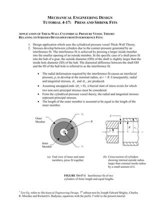
  • 1. MECHANICAL ENGINEERING DESIGN TUTORIAL 4-17: PRESS AND SHRINK FITS APPLICATION OF THICK-WALL CYLINDRICAL PRESSURE VESSEL THEORY RELATING TO STRESSES DEVELOPED FROM INTERFERENCE FITS: 1. Design application which uses the cylindrical pressure vessel Thick-Wall Theory. 2. Stresses develop between cylinders due to the contact pressure generated by an interference fit. The interference fit is achieved by pressing a larger inside member into the smaller opening of an outside member. In the specific case of a shaft press fit into the hub of a gear, the outside diameter (OD) of the shaft is slightly larger than the inside hole diameter (ID) of the hub. The diametral difference between the shaft OD and the ID of the hub hole is referred to as the interference fit. • The radial deformation required by the interference fit causes an interfacial pressure, p, to develop at the nominal radius, at r = R. Consequently, radial and tangential stresses, σ r and σ t , are produced. • Assuming uncapped ends ( 0), l σ = a biaxial state of stress exists for which two non-zero principal stresses must be considered. • From the cylindrical pressure vessel theory, the radial and tangential stresses represent principal stresses. • The length of the outer member is assumed to be equal to the length of the inner member. ro δ R ro ri (b) Cross-section of cylinders showing internal outside radius larger than external inside radius by a small amount of δ. ri Outer Member Inner Member (a) End view of inner and outer members, press fit together. R FIGURE T4-17-1 Interference fit of two cylinders of finite length and equal lengths. † Text Eq. refers to Mechanical Engineering Design, 7th edition text by Joseph Edward Shigley, Charles R. Mischke and Richard G. Budynas; equations with the prefix T refer to the present tutorial.
  • 2. 3. Referring to Fig. T4-17-1, the geometric features of the cylindrical parts are defined as: the inside radius of the inner cylinder nominal radius of internal outside radius and external inside radius after assembly outside radius of the outer cylinder radial interference r i R r o δ = = = = INSIDE CYLINDER • Inner member experiences an external pressure, po = p, resulting in compressive tangential and radial stresses. • Thick-Wall Theory may be applied with ro = R: 2 σ = − p R + r 2 ( ) i t i r = R o = − pC it (Text Eq.4-57) 2 2 R − r i ( σ ) = − p = − p r i r = R o OUTSIDE CYLINDER • Outer member only experiences internal pressure, pi = p, resulting in tensile tangential stress and compressive radial stress. • Thick-Wall Theory is, as always, applicable with ri = R: 2 2 ( σ r ) = p o + R t o r = R i = pC (Text Eq. 4-58) r 2 − R 2 ot o ( σ ) = − p = − p r i r = R i DEFINITION OF INTERFACIAL PRESSURE We presently have two equations and three unknowns for both the inside and outside cylinder analyses. A third equation which relates the contact pressure and the interference can be derived by examining the deformation of the members. Deflection Equation The total radial interference may be defined as: δ total = δ i + δ o where, Shigley, Mischke Budynas Machine Design Tutorial 4-17: Press and Shrink Fits 2/11
  • 3. decrease in radius of inner cylinder increase in radius of hole δ δ i o = = The deformation may also be expressed as: δ total = pRKi + pRKo (Modified Text Eq. 4-59) where the outside member constant, Ko, is defined as, + = + = + K r R C [ ] 2 2 2 2 1 o 1 ν ν o o o o E r R E −
  • 4. o o o Using the radius ratio form defined for the cylindrical pressure vessel formulation,ζ o = ro / R , we can define 2 2 1 1 C ζ = o + o ζ o − Note that the Co term is a function of geometry only, while the member constant term Ko is a function of both geometry and material parameters. Similarly for the inside member constant Ki, + = − = − K R r C [ ] 2 2 2 2 1 i 1 ν ν i i i i E R r E −
  • 5. i i i with ζ i = R / ri , Ci is defined as: 2 2 1 1 C ζ = i + i ζ i − For the case of a solid shaft, ri = 0, ζ i = R / ri = ∞ and Ci = 1. We can now solve for the deformation for a given class of interference fits, δ total = [Ko + Ki ]pR Or, rearranging, the contact pressure, p, may be expressed as a function of the interference without assumptions regarding material property values: 1 δ total p (Modified Text Eq. 4-60) R = Ko Ki + Shigley, Mischke Budynas Machine Design Tutorial 4-17: Press and Shrink Fits 3/11
  • 6. Example T4.17.1: Shaft Hub Shrink Fit Problem Statement: A carbon-steel gear hub having a nominal hole diameter of 1 inch is to be shrink-fitted to a carbon-steel shaft using a class FN4 fit. The hub has a nominal thickness of ½ inch. Find: 1. the maximum tangential and radial stresses in the hub and shaft when the loosest fit is obtained; 2. the same as (a), except using the tightest fit as a condition. Solution Methodology: 1. Using Table A-1-2 of this document, identify the diametral size ranges for the shaft and the hole based on an ANSI US Customary Standard class FN4 fit which is discussed below. 2. Calculate the interferences for the loosest and tightest fits. 3. Compute the interfacial pressure for the loosest and tightest fits. 4. For each fit, calculate the radial and tangential stresses for both the hub and the shaft. Schematic: Solution: Shaft 1. Shaft and Hub Size Ranges: Hub This problem specifies a class FN4 fit. The class FN4 fit is a specification defined by the American National Standards Institute (ANSI), American Standard Limits for Cylindrical Parts ANSI B4.1-1978. The FN4 fit is a “Force fit suitable for parts which can be highly stressed or for shrink fits where the heavy pressing forces required are impractical.” Excerpts from the ANSI B4.1-1978 standard are provided in Table A-1 of this tutorial. From Table A-1-2, for a nominal shaft/hole diameter of 1 in., the appropriate size range is 0.95–1.19 in. The allowable tolerances, in thousandths of an inch, are: † Text Eq. refers to Mechanical Engineering Design, 7th edition text by Joseph Edward Shigley, Charles R. Mischke and Richard G. Budynas; equations with the prefix T refer to the present tutorial.
  • 7. Largest Tolerance Smallest Tolerance (10-3 in.) (10-3 in.) Hub hole +0.8 –0.0 Shaft +2.3 +1.8 The shaft and hub size ranges for a nominal 1 in. diameter are: Largest Diameter Smallest Diameter (in.) (in.) Hub hole 1.0008 1.0000 Shaft 1.0023 1.0018 2. Diametral and Radial Interference Calculations: Loosest Fit Tightest Fit Hub hole 1.0008 1.0000 Shaft 1.0018 1.0023 –0.0010 –0.0023 The radial interferences are therefore δ = –0.0005 in. (loosest fit) and δ = –0.001 15 in. (tightest fit). The interference is taken as a positive number by convention. Consequently, the radial interferences for the two cases are: δ = 0.0005 in. (loosest fit) δ = 0.001 15 in. (tightest fit) 3. Interfacial Pressure The interface pressure can be computed from Modified Eq. (4-60): 1 δ total R = Ko Ki + p For this problem, the geometric features have been defined as: r = d + t = + = r = R = d = 1 in. 0.5 in. 1.0 in. 0.0 0.5 in. o 2 2 i 2 Thus, for the hub (outside member), Shigley, Mischke Budynas Machine Design Tutorial 4-17: Press and Shrink Fits 5/11
  • 8. (1 in.) 2 (0.5 in.) 1 (2) 1 5 1.6667 1 (2) 1 3 = = = 2 2 2 2 r o R = + = + = = ζ ζ o o − − 1 1 1.667 0.292 6.5289 10 (1/psi) [ ] ( )[ ] ν − 8 = + = + = × 6 × 30 10 psi ζ o C o K C o o o E o Similarly for the shaft (inside member) ζ = =∞ i R r i = + = 1 1.0 1 ζ i ζ i − 1 1 1.0 0.292 2.360 10 (1/psi) [ ] ( )[ ] 2 2 ν − 8 = − = − = × 6 × 30 10 psi C i K C i i i E i For the loosest fit case: δ = 1 1 0.0005 loosest fit = + × + ×
  • 9. = 11 250 psi (loosest fit) p loosest fit 8 8 K K − − R 6.5289 10 2.360 10 0.5 o i For the tightest fit case: δ 1 1 0.00115 = tightest fit = + × + ×
  • 10. = 25 875 psi (tightest fit) p tightest fit 8 8 K K − − R 6.5289 10 2.360 10 0.5 o i 4. Radial Tangential Stress Calculations for Shaft and Hub: Loosest Fit (p = 11 250 psi) Hub: σr (r = R) = − p = −11 250 psi 2 2 ( r R ) p r R o pC (11 250psi)(1.6667) 2 2 σ = = + = = = t o r R o − 18 750 psi Shaft: σr (r = R) = − p = −11 250 psi 2 2 ( r R ) p R r i pC ( 11 250 psi)(1) 2 2 σ = = − + = − = − = − t i R r i − 11 250 psi Tightest Fit (p = 25 875 psi) Shigley, Mischke Budynas Machine Design Tutorial 4-17: Press and Shrink Fits 6/11
  • 11. Hub: σr (r = R) = − p = −25 875 psi 2 2 ( r R ) p r R o pC (25 875psi)(1.6667) 2 2 σ = = + = = = t o r R o − 43 125 psi Shaft: σr (r = R) = − p = −25 875 psi 2 2 ( r R ) p R r i pC ( 25 875psi)(1) 2 2 σ = = − + = − = − = − t i R r i − 25 875 psi Thus the shaft has equal radial and tangential stress for each tightness condition, whereas, the hub’s tangential stress is consistently higher than its radial stress for both the loosest and the tightest condition. Note: Since the shaft length is greater than the hub length, which is typical in practice, this design case violates one of the assumptions of the interfacial pressure development. In this case, there would be an increase in the interfacial pressure at each end of the hub. This condition of increased interfacial pressure would typically be accounted for by applying a stress concentration factor, Kt, for stresses calculated at points at the end of the hub such as, K K σ = σ t actual t , tangential t σ = σ r actual t , radial r Shigley, Mischke Budynas Machine Design Tutorial 4-17: Press and Shrink Fits 7/11
  • 12. Table A-1 LIMITS AND FITS FOR CYLINDRICAL PARTS† The limits shown in the accompanying tabulations are in thousandths of an inch. The size ranges include all sizes over the smallest size in the range, up to and including the largest size in the range. The letter symbols are defined as follows: RC Running and sliding fits are intended to provide a similar running performance, with suitable lubrication allowance, throughout the range of sizes. The clearance for the first two classes, used chiefly as slide fits, increases more slowly with diameter than the other classes, so that accurate location is maintained even at the expense of free relative motion. RC1 Close sliding fits are intended for the accurate location of parts which must assemble without perceptible play. RC2 Sliding fits are intended for accurate location but with greater maximum clearance than class RC1. Parts made to this fit move and turn easily, but are not intended to run freely, and in the larger sizes may seize with small temperature changes. RC3 Precision running fits are about the closest fits which can be expected to run freely and are intended for precision work at slow speeds and light journal pressures, but are not suitable where appreciable temperature differences are likely to be encountered. RC4 Close running fits are intended chiefly for running fits on accurate machinery with moderate surface speeds and journal pressures, where accurate location and minimum play is desired. RC5–RC6 Medium running fits are intended for higher running speeds, heavy journal pressures, or both. RC7 Free running fits are intended for use where accuracy is not essential or where large temperature variations are likely to be encountered, or under both of these conditions. RC8–RC9 Loose running fits are intended for use where wide commercial tolerances may be necessary, together with an allowance, on the external member. L Locational fits are fits intended to determine only the location of the mating parts; they may provide rigid or accurate location, as with interference fits, or provide some freedom of location, as with clearance fits. Accordingly, they are divided into three groups: clearance fits, transition fits, and interference fits. LC Locational clearance fits are intended for parts which are normally stationary but which can be freely assembled or disassembled. They run from snug fits for parts requiring accuracy of location, through the medium clearance fits for parts such as ball, race, and housing, to the looser fastener fits where freedom of assembly is of prime importance. LT Locational transition fits are a compromise between clearance and interference fits, for application where accuracy of location is important, but either a small amount of clearance or interference is permissible. LN Locational interference fits are used where accuracy of location is of prime importance and for parts requiring rigidity and alignment with no special requirements for bore pressure. Such fits are not intended for parts designed to transmit frictional loads form one part to another by virtue of the tightness of fit, since these conditions are covered by force fits. FN Force and shrink fits constitute a special type of interference fit, normally characterized by maintenance of constant bore pressure throughout the range of sizes. The interference therefore varies almost directly with diameter, and the difference between its minimum and maximum value is small so as to maintain the resulting pressures within reasonable limits. FN1 Light drive fits are those requiring light assembly pressures and producing more or less permanent assemblies. They are suitable for thin sections or long fits or in cast-iron external members. FN2 Medium drive fits are suitable for ordinary steel parts or for shrink fits on light sections. They are about the tightest fits that can be used with high-grade cast-iron external members. FN3 Heavy drive fits are suitable for heavier steel parts or for shrink fits in medium sections. FN4–FN5 Force fits are suitable for parts which can be highly stressed or for shrink fits where the heavy pressing forces required are impractical. †Extracted from American Standard Limits for Cylindrical Parts ANSI B4.1-1978, with the permission of the publishers, The American Society of Mechanical Engineers, United Engineering Center, 345 East 47th Street, New York 10017. Limit dimensions are tabulated in this standard for nominal sizes up to and including 200 in. An SI version is also available. Shigley, Mischke Budynas Machine Design Tutorial 4-17: Press and Shrink Fits 8/11
  • 13. Table A-1-1 RUNNING AND SLIDING FITS Diameter Size Range (in.) Class 0.00 - 0.12 0.12 - 0.24 0.24 - 0.40 0.40 - 0.71 RC1 Hole +0.20 -0.00 +0.20 -0.00 +0.25 -0.00 +0.30 -0.00 Shaft +0.10 -0.25 -0.15 -0.30 -0.20 -0.35 -0.25 -0.45 RC2 Hole +0.25 -0.00 +0.30 -0.00 +0.40 -0.00 +0.40 -0.00 Shaft -0.10 -0.30 -0.15 -0.35 -0.20 -0.45 -0.25 -0.55 RC3 Hole +0.40 -0.00 +0.50 -0.00 +0.60 -0.00 +0.70 -0.00 Shaft -0.30 -0.55 -0.40 -0.70 -0.50 -0.90 -0.60 -1.00 RC4 Hole +0.60 -0.00 +0.70 -0.00 +0.90 -0.00 +1.00 -0.00 Shaft -0.30 -0.70 -0.40 -0.90 -0.50 -1.10 -0.60 -1.30 RC5 Hole +0.60 -0.00 +0.70 -0.00 +0.90 -0.00 +1.00 -0.00 Shaft -0.60 -1.00 -0.80 -1.30 -1.00 -1.60 -1.20 -1.90 RC6 Hole +1.00 -0.00 +1.20 -0.00 +1.40 -0.00 +1.60 -0.00 Shaft -0.60 -1.20 -0.80 -1.50 -1.00 -1.90 -1.20 -2.20 RC7 Hole +1.00 -0.00 +1.20 -0.00 +1.40 -0.00 +1.60 -0.00 Shaft -1.00 -1.60 -1.20 -1.90 -1.60 -2.50 -2.00 -3.00 RC8 Hole +1.60 -0.00 +1.80 -0.00 +2.20 -0.00 +2.80 -0.00 Shaft -2.50 -3.50 -2.80 -4.00 -3.00 -4.40 -3.50 -5.10 RC9 Hole +2.50 -0.00 +3.00 -0.00 +3.50 -0.00 +4.00 -0.00 Shaft -4.00 -5.60 -4.50 -6.00 -5.00 -7.20 -6.00 -8.80 Diameter Size Range (in.) Class 0.71 - 1.19 1.19 - 1.97 1.97 - 3 .15 3.15 - 4.73 RC1 Hole +0.40 -0.00 +0.40 -0.00 +0.50 -0.00 +0.60 -0.00 Shaft -0.30 -0.55 -0.40 -0.70 -0.40 -0.70 -0.50 -0.90 RC2 Hole +0.50 -0.00 +0.60 -0.00 +0.70 -0.00 +0.90 -0.00 Shaft -0.30 -0.70 -0.40 -0.80 -0.40 -0.90 -0.50 -1.10 RC3 Hole +0.80 -0.00 +1.00 -0.00 +1.20 -0.00 +1.40 -0.00 Shaft -0.80 -1.30 -1.00 -1.60 -1.20 -1.90 -1.40 -2.30 RC4 Hole +1.20 -0.00 +1.60 -0.00 +1.80 -0.00 +2.20 -0.00 Shaft -0.80 -1.60 -1.00 -2.00 -1.20 -2.40 -1.40 -2.80 RC5 Hole +1.20 -0.00 +1.60 -0.00 +1.80 -0.00 +2.20 -0.00 Shaft -1.60 -2.40 -2.00 -3.00 -2.50 -3.70 -3.00 -4.40 RC6 Hole +2.00 -0.00 +2.50 -0.00 +3.00 -0.00 +3.50 -0.00 Shaft -1.60 -2.80 -2.00 -3.60 -2.50 -4.30 -3.00 -5.20 RC7 Hole +2.00 -0.00 +2.50 -0.00 +3.00 -0.00 +3.50 -0.00 Shaft -2.50 -3.70 -3.00 -4.60 -4.00 -5.80 -5.00 -7.20 RC8 Hole +3.50 -0.00 +4.00 -0.00 +4.50 -0.00 +5.00 -0.00 Shaft -4.50 -6.50 -5.00 -7.50 -6.00 -9.00 -7.00 -10.50 RC9 Hole +5.00 -0.00 +6.00 -0.00 +7.00 -0.00 +9.00 -0.00 Shaft -7.00 -10.50 -8.00 -12.00 -9.00 -13.50 -10.00 -15.00 Shigley, Mischke Budynas Machine Design Tutorial 4-17: Press and Shrink Fits 9/11
  • 14. Table A-1-2 FORCE AND SHRINK FITS Diameter Size Range (in.) Class 0.00 - 0.12 0.12 - 0.24 0.24 - 0.40 0.40 - 0.56 FN1 Hole +0.25 -0.00 +0.30 -0.00 +0.40 -0.00 +0.40 -0.00 Shaft +0.50 +0.30 +0.60 +0.40 +0.75 +0.50 +0.80 +0.50 FN2 Hole +0.40 -0.00 +0.50 -0.00 +0.60 -0.00 +0.70 -0.00 Shaft +0.85 +0.60 +1.00 +0.70 +1.40 +1.00 +1.60 +1.20 FN3 Hole Shaft FN4 Hole +0.40 -0.00 +0.50 -0.00 +0.60 -0.00 +0.70 -0.00 Shaft +0.95 +0.70 +1.20 +0.90 +1.60 +1.20 +1.80 +1.40 FN5 Hole +0.60 -0.00 +0.70 -0.00 +0.90 -0.00 +1.00 -0.00 Shaft +1.30 +0.90 +1.70 +1.20 +2.00 +1.40 +2.30 +1.60 Diameter Size Range (in.) Class 0.56 - 0.71 0.71 - 0.95 0.95 - 1.19 1.19 - 1.58 FN1 Hole +0.40 -0.00 +0.50 -0.00 +0.50 -0.00 +0.60 -0.00 Shaft +0.90 +0.60 +1.10 +0.70 +1.20 +0.80 +1.30 +0.90 FN2 Hole +0.70 -0.00 +0.80 -0.00 +0.80 -0.00 +1.00 -0.00 Shaft +1.60 +1.20 +1.90 +1.40 +1.90 +1.40 +2.40 +1.80 FN3 Hole +0.80 -0.00 +1.00 -0.00 Shaft +2.10 +1.60 +2.60 +2.00 FN4 Hole +0.70 -0.00 +0.80 -0.00 +0.80 -0.00 +1.00 -0.00 Shaft +1.80 +1.40 +2.10 +1.60 +2.30 +1.80 +3.10 +2.50 FN5 Hole +1.00 -0.00 +1.20 -0.00 +1.20 -0.00 +1.60 -0.00 Shaft +2.50 +1.80 +3.00 +2.20 +3.30 +2.50 +4.00 +3.00 Diameter Size Range (in.) Class 1.58 - 1.97 1.97 - 2.56 2.56 - 3 .15 3.15 - 3.94 FN1 Hole +0.60 -0.00 +0.70 -0.00 +0.70 -0.00 +0.90 -0.00 Shaft +1.40 +1.00 +1.80 +1.30 +1.90 +1.40 +2.40 +1.80 FN2 Hole +1.00 -0.00 +1.20 -0.00 +1.20 -0.00 +1.40 -0.00 Shaft +2.40 +1.80 +2.70 +2.00 +2.90 +2.20 +3.70 +2.80 FN3 Hole +1.00 -0.00 +1.20 -0.00 +1.20 -0.00 +1.40 -0.00 Shaft +2.80 +2.20 +3.20 +2.50 +3.70 +3.00 +4.40 +3.50 FN4 Hole +1.00 -0.00 +1.20 -0.00 +1.20 -0.00 +1.40 -0.00 Shaft +3.40 +2.80 +4.20 +3.50 +4.70 +4.00 +5.90 +5.00 FN5 Hole +1.60 -0.00 +1.80 -0.00 +1.80 -0.00 +2.20 -0.00 Shaft +5.00 +4.00 +6.20 +5.00 +7.20 +6.00 +8.40 +7.00 Shigley, Mischke Budynas Machine Design Tutorial 4-17: Press and Shrink Fits 10/11
  • 15. Table A-1-2 FORCE AND SHRINK FITS (CONTINUED) Diameter Size Range (in.) Class 3.94 - 4.73 4.73 - 5.52 5.52 - 6.30 6.30 - 7.09 FN1 Hole +0.90 -0.00 +1.00 -0.00 +1.00 -0.00 +1.00 -0.00 Shaft +2.60 +2.00 +2.90 +2.20 +3.20 +2.50 +3.50 +2.80 FN2 Hole +1.40 -0.00 +1.60 -0.00 +1.60 -0.00 +1.60 -0.00 Shaft +3.90 +3.00 +4.50 +3.50 +5.00 +4.00 +5.50 +4.50 FN3 Hole +1.40 -0.00 +1.60 -0.00 +1.60 -0.00 +1.60 -0.00 Shaft +4.90 +4.00 +6.00 +5.00 +6.00 +5.00 +7.00 +6.00 FN4 Hole +1.40 -0.00 +1.60 -0.00 +1.60 -0.00 +1.60 -0.00 Shaft +6.90 +6.00 +8.00 +7.00 +8.00 +7.00 +9.00 +8.00 FN5 Hole +2.20 -0.00 +2.50 -0.00 +2.50 -0.00 +2.50 -0.00 Shaft +9.40 +8.00 +11.60 +10.00 +13.60 +12.00 +13.60 +12.00 Shigley, Mischke Budynas Machine Design Tutorial 4-17: Press and Shrink Fits 11/11