result management system report for college project
Fpl gtr148 (1)
1. Design of a Hydraulic
Bending Machine
Steve Hankel
Marshall Begel
United States
Department of
Agriculture
Forest Service
Forest
Products
Laboratory
General
Technical
Report
FPL−GTR−148
2. Abstract
To keep pace with customer demands while phasing out old
and unserviceable test equipment, the staff of the Engineer-
ing Mechanics Laboratory (EML) at the USDA Forest Ser-
vice, Forest Products Laboratory, designed and assembled a
hydraulic bending test machine. The EML built this machine
to test dimension lumber, nominal 2 in. thick and up to 12 in.
deep, at spans up to 20 ft and loads up to 20,000 lbf. The
hydraulic bending test machine was built using parts of a
100,000-lbf compression test frame. Added components
included W12 by 65 steel beams; steel tube sections, L-
sections, and threaded rods for beam attachment; I-beam
spacer plates; wood block beam end supports; a 4-in. bore,
10-in. stroke hydraulic cylinder with 38,000 lbf capacity;
steel plates for cylinder reinforcement; and two pivoting
four-point load head assemblies. Eccentric loads that might
occur during a test will not yield the positioning screws of
the machine head or otherwise affect test results.
Keywords: hydraulic bending machine, dimension lumber,
wood testing machine
April 2004
Hankel. Steven G.; Begel, Marshall. 2004 Design of a hydraulic bending
machine Res. Note FPL-GTR-148. Madison, WI: U.S. Department of
Agriculture, Forest Service, Forest Products Laboratory. 5 p.
A limited number of free copies of this publication are available to the
public from the Forest Products Laboratory, One Gifford Pinchot Drive,
Madison, WI 53726–2398. This publication is also available online at
www.fpl.fs.fed.us. Laboratory publications are sent to hundreds
of libraries in the United States and elsewhere.
The Forest Products Laboratory is maintained in cooperation with the
University of Wisconsin.
The use of trade or firm names in this publication is for reader information
and does not imply endorsement by the U.S. Department of Agriculture of
any product or service.
The United States Department of Agriculture (USDA) prohibits discrimina-
tion in all its programs and activities on the basis of race, color, national
origin, sex, religion, age, disability, political beliefs, sexual orientation, or
marital or familial status. (Not all prohibited bases apply to all programs.)
Persons with disabilities who require alternative means for communication
of program information (Braille, large print, audiotape, etc.) should contact
the USDA’s TARGET Center at (202) 720–2600 (voice and TDD). To file a
complaint of discrimination, write USDA, Director, Office of Civil Rights,
Room 326-W, Whitten Building, 1400 Independence Avenue, SW,
Washington, DC 20250–9410, or call (202) 720–5964 (voice and TDD).
USDA is an equal opportunity provider and employer.
SI conversion factors
English unit
Conversion
factor SI unit
inch (in.) 25.4 millimeters (mm)
in
4
4.162×10
–7
m
4
foot (ft) 0.3048 meter (m)
pound, mass (lb) 0.454 kilogram (kg)
pound, force (lbf) 4.45 newton (N)
pound force/in
2
(lbf/in
2
) 6.894 kilopascal (kPa)
in–lb 0.113 joule (J)
gallon 3.785 liter (L)
Dimensional lumber equivalents
nominal 2 by 4 in. standard 38 by 89 mm
nominal 2 by 12 in. standard 38 by 286 mm
3. Design of a Hydraulic Bending Machine
Steve Hankel, Instrument Maker
Marshall Begel, Civil Engineer
Forest Products Laboratory, Madison, Wisconsin
Introduction
To keep pace with customer demands while phasing out old
and unserviceable test equipment, the staff of the Engineer-
ing Mechanics Laboratory (EML) at the USDA Forest Ser-
vice, Forest Products Laboratory, designed and assembled a
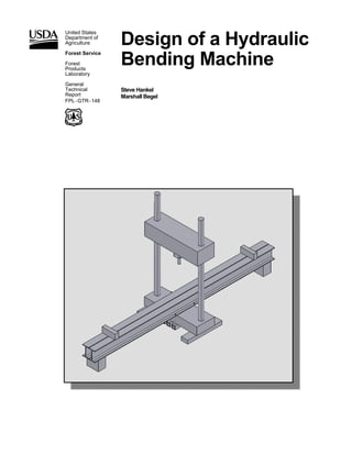
hydraulic bending test machine (Fig. 1). The machine is used
to support long-span beams and to apply a hydraulically
driven bending force to the beams in accordance with stan-
dard testing procedures. This paper describes the parameters
and considerations for designing this machine to enable the
EML staff to complete needed tests in a manner that is user-
friendly and safe.
The mission of the EML is to test and evaluate wood, wood
products, and wood component specimens to determine their
mechanical and material properties. Tests are performed for
work units within the Forest Products Laboratory and for
work units in off-site Forest Service Experimental Stations
by special request.
The EML performs a significant portion of its testing on
dimension lumber, including static bending tests that
conform to the ASTM D198 standard (ASTM 1997).
The primary purpose of the bending machine is to test long-
span dimension lumber (nominal 2- by 4-in. to 2- by 12-in.,
up to 20 ft in length) at expected loads less than 10,000 lb
and deflections less than 6 in. Two machines that have been
used by the EML for bending tests are the 160,000-lbf
Reihle machine (purchased in 1969) and the 25,000-lbf box-
test machine (purchased in 1937). These machines are of
questionable reliability and repairability because of their age.
A machine that is capable of testing long-span dimension
lumber is not currently in production and would have to be
custom-made at great expense. Therefore, we chose to mod-
ify a 100,000-lbf compression test frame with a motor-
driven movable head box, which was donated to EML.
Many parts of the test frame were removed, leaving the steel
feet, slab, head box positioning screws, and head box. Parts
that were added to complete the bending test machine in-
cluded two wide-flange beams, beam attachment hardware,
beam spacer plates, beam end supports, a hydraulic cylinder,
cylinder reinforcement hardware, and two four-point load
head assemblies. Design considerations for these compo-
nents are presented in this paper.
Although the 100,000-lbf compression force capacity of the
original frame design is much greater than the loads we
encounter during bending tests, we discuss the effects of
eccentric loads that are more likely to occur in bending tests
than in the compression tests for which the frame was
designed.
I-Beam
Selection
The following deflection equation for simple support and
center load was used:
3
48
PL
EI
δ = for L = 240 in., E = 2.9 × 10⁷
lbf/in2
where
δ is deflection,
P force,
L length,
E modulus of elasticity, and
I moment of inertia.
Figure 1—Hydraulic bending machine.
Slab
Head box
Head box
positioning screw
Foot
I-beam
Hydraulic cylinder
Stabilization block
Beam
attachment
4. 2
The force required to break a strong Southern Pine 16-ft-
long 2 by 12 board with a modulus of rupture of
14,500 lbf/in2
(Forest Products Laboratory 1999) is less than
10,000 lbf. For this calculation, we assumed service load
(maximum expected) to be 20,000 lbf, or 10,000 lbf per steel
beam. Ultimate load (based on known capacity of test frame)
is 50,000 lbf per beam.
For the I-beam to have a 0.20-in. maximum service deflec-
tion and a 1-in. maximum ultimate deflection, the minimum
required moment of inertia, I, is 993 in4
. Since it was a prior-
ity to keep the beam depth small to facilitate loading of
specimens, we selected two W12 by 65 sections. The com-
bined I is 1,066 in4
(AISC 1995).
Because the beam webs are connected by six spacer plates
(described later in this paper), movement associated with
lateral–torsional buckling will be prevented. However, the
W12 by 65 section is one of the few “non-compact” sections
that is susceptible to local flange and web buckling. Beam
strength was calculated using the procedure for calculating
capacity of a non-compact section (AISC 1995).
The actual yield stress of the beam material was not speci-
fied. A higher grade of steel (50,000 lbf/in2
) would have
greater flexural strength than does a lower grade
(36,000 lbf/in2
), but it would be susceptible to local buck-
ling. For this analysis, the plastic moment of a
36,000-lbf/in2
W12 by 65 beam was calculated and com-
pared to the local buckling moments of a 50,000-lbf/in2
W12
by 65 beam. The minimum of these limit states is considered
to be the strength of the beam.
The design plastic bending moment (ΦMp) of the 36,000-
lbf/in2
beam is 261,000 in-lbf. Since the shape of this mate-
rial is not susceptible to local buckling, this is also ΦMn', the
flexural design strength.
The design plastic bending moment of the 50,000-lbf/in2
beam, ΦMp, is 363,000 in-lbf. However, the shape of this
material is susceptible to local flange buckling, which re-
duces this value to 358,000 in-lbf. The shape is not suscepti-
ble to local web buckling, so the factored flexural design
strength of the 50,000-lbf/in2
beam is 358,000 in-lbf.
The adjusted maximum unbraced length, LP', of a
50,000-lbf/in2
beam is 11.8 ft and that for a 36,000-lbf/in2
beam is 12.6 ft. Both of these are greater than the distance
between the edge of the frame slab to the reaction head, so
the flexural design strength of both beams, ΦMn', is equal to
their nominal factored flexural strengths, ΦMn. Thus, the
factored nominal flexural strength of a W12 by 65 beam of
unspecified material (minimum 36,000-lbf/in2
steel) is
261,000 in-lbf. Since the maximum load of the original
frame (100,000 lbf) would put only 250,000 ft-lbf on the
beams, the beams will be adequate for any test designed to
the limits of the other frame components.
Attachment
The beams are not directly attached to the frame. Rather,
they are strapped down with six 5/8-in. threaded rods that
are connected to three steel 3- by 3- by 1/4-in. tube sections
that pass under the frame slab (Fig. 2). The rods pass
through two 3- by 2- by 3/8-in. steel L-sections that keep the
beams from rotating with respect to the frame slab.
Any upward load on these components would come from a
release of load from a specimen break. Then, the energy
stored in the steel beams might cause the beams to spring
upwards and be lifted from the slab. We calculated the
significance of this effect.
Assuming that a specimen broke under a design load of
20,000 lbf, the beam ends would deflect about 0.19 in., as
described previously. Given material and sectional proper-
ties, and assuming the beam behaves as an upside-down
simply supported long-span beam, it would possess a poten-
tial energy of 1,900 in-lbf. Assuming an instantaneous speci-
men failure, this internal energy would be converted to some
combination of kinetic energy of the vibrating beam, internal
spring energy with upward deflection of the ends, internal
friction loss (hysteresis), gravity potential energy of the
lifted beams, and spring energy of the six stretched threaded
rods. It is conservative to assume that all the beam energy
present before the break would be entirely converted to the
gravity potential energy of the beam and the spring energy of
the stretched threaded rods. Both of these energy terms are
dependent on the height achieved by the beams. An iterative
calculation shows that the beams would lift less than
3/1,000 in.
Spacer Plates
Six 2-in.-thick plates are used to separate and stabilize the
two W12 by 65 steel beams (Fig. 3). The plates are placed
1 ft from each end, at the coordinate of the slab edge of the
frame, and halfway between these two, at an approximate
Figure 2—I-Beam attachment.
5. 3
distance of 4-1/2 ft. Each plate is bolted to the beam web by
four 3/4-in. grade 5 bolts. The plates are wide enough to
maintain a 1-1/4-in. gap between the beams, so that fixtures
and reaction heads may be affixed with T-slot hardware.
Any load on the spacer plates would be due to slight eccen-
tricities in the test. Assuming a 10° load eccentricity on a
100,000-lbf vertical load, there would be 17,000-lbf horizon-
tal force. Assume that this force is also a vertical force dif-
ference between the beams. Even if this entire force is sup-
ported by the four 3/4-in. bolts located closest to the slab, the
bearing stress in the beam web would be less than 40% the
yield stress of 36,000-lbf/in2
mild steel, and the combined
bearing and tensile stress in the bolts would be less than
40% the yield stress of grade 5 steel.
Stabilization Blocks
Wood blocks cut from glulam beams are fastened under-
neath the ends of the steel beams. The purpose of the wood
blocks is to stabilize the machine and to minimize rocking or
tipping when objects are placed on the beam ends. This is
not expected to happen during a test. The wood blocks are
not designed to take any test load because the large test loads
will be contained within the machine structure and not trans-
ferred to the floor. The wood blocks also add a degree of
safety if someone accidentally walks into the beam end. For
example, an individual will likely hit a shoe against the
wood block rather than a knee against the steel edge.
The blocks are made of Douglas-fir with grain parallel to the
floor. The blocks were cut so as to leave a 1/4-in. gap be-
tween the block and the floor. Thus, the beam end will be
allowed to deflect its design value of 0.20 in. during a test
without the block touching the floor.
Screw Bending Consideration
If the load should develop an eccentricity in the plane of the
bending specimen, it would place a bending moment on the
5-in. screws of the machine frame. We examined this
situation to see if it posed a danger of damaging the screws
or otherwise affecting test results. Assuming a load of
100,000 lb and an eccentricity of 10° degrees from vertical,
there will be a horizontal force on the load head of 8,700 lbf,
or about 4,350 lbf per screw. If the load head is 30 in. from
the base of the frame slab (based on a steel beam height of
12 in., reaction support height of 6 in., and specimen depth
of 12 in.), there would be a moment of 260,000 in-lbf, or
130,000 in-lbf per screw. This would cause a stress at the
base of the screw of about 21 ksi and a horizontal deflection
of 0.09 in. This is unlikely to affect the test results or
damage the machine.
Hydraulic Cylinder
We chose a hydraulic cylinder instead of a screw-drive
loading mechanism. A hydraulic machine allows for con-
stant load control and makes fast corrections after minor
failures and load redistributions during a test, compared to
the response of a screw drive. A hydraulic test machine also
has greater flexibility for cyclic and vibrational testing than
does a screw-driven machine.
The cylinder will be used with an existing MTS model
510.10 hydraulic power supply (MTS Systems Corporation,
Eden Prairie, Minnesota). This power supply uses a fixed-
volume pump to provide a fluid flow of 10 gal/min at
3,000 lbf/in2
. The pump motor requires a three-phase 460-V,
60-Hz electrical power source at 34 continuous amps. Fluid
will be regulated through a model A076 Moog servovalve
(Moog Inc., East Aurora, New York). This is a two-stage
flow control servovalve with a mechanical feedback pilot
stage and a rated flow of 1 to 17 gal/min (at 1,000-lbf/in2
pressure drop). The operating pressure is 3,000 lbf/in2
, and
the step response at this pressure is 3 to 16 ns for 100%
stroke. Load will be measured by a Sensotec model
UG/4671-03 load cell (Sensotec, Inc., Columbus, Ohio)
with a capacity of 30,000 lbf.
Cylinder Specifications
We selected the hydraulic cylinder from the Miller Fluid
Power catalogue (Miller Fluid Power 2003). The specifica-
tions for the cylinder and associated parts are as follows.
Cylinder
• Centerline mounting
• 4-in. bore—At 3,000 lbf/in2
, a 4-in. bore will provide a
force of 37,698 lbf (π × d2
× pressure ÷ 4) (according to
bore size estimation table).
• 0.0544 gal/in. oil consumption—If we assume a 6-in.
deflection over 5 min, oil consumption in gallons/min is
0.065. The capacity of the pump we have is sufficient.
Figure 3—I-Beam spacer plates.
6. 4
Stop tube recommendation
• Model 68 is the last entry in Group B
• For an unguided piston rod, L = 4D, for D = stroke
if D = 10, L = 40
• Maximum length L = 40 for no recommended stop tube—
If 40 < L < 50, a 1-in. stop tube is recommended. No stop
tube was ordered.
According to the oversize piston table (Miller Fluid
Power 2003), the recommended diameter for L = 40 and
load = 40,000 lbf is 2.0 in. We chose a model with a
4-in. bore/2.5-in. rod, which corresponds to L = 74 (18.5-in.
stroke). This is slightly larger than that recommended by
Miller. These recommendations are based on a compromise
between the flexibility of thinner rods and the strength of
thicker rods.
Cylinder parameters
H Series
68 Mounting style
B Bushing (bolted)
3 Rod end style (female, long)
B Cushions, both ends
00400 Bore diameter, 4 in.
01000 Stroke, 10 in.
00250 Rod diameter, 2.5 in.
S Port type (Society of Automotive Engineers)
2 Port location (2 or 4)
0 Modified, standard
Cylinder Reinforcement
The cylinder is attached to the movable frame head only at
the cylinder base; therefore, reinforcement was needed to
resist horizontal forces. We placed two 2-in.-thick steel
plates on either side of the cylinder (Fig. 4). A 1/2-in.-deep
and 5-in.-wide groove was cut into each plate to secure the
edges of the lower block of the cylinder in four directions.
The plates are shaped to remove large corner sections (to
reduce weight) and to accommodate the hydraulic fitting on
the cylinder base. Each plate is attached inside the frame
head with four bolts to provide moment resistance in both
directions.
Assuming 10° load eccentricity (from vertical), a 20,000-lbf
load would put a 3,500-lbf horizontal force on the load head.
We conservatively assumed that this force would be applied
to a single plate. If the load head is 38 in. from the screw
connection point (6 in. specimen deflection + 6 in. load head
+ 8 in. load cell + 18 in. cylinder height), the moment on the
cylinder would be 132,000 in-lbf. This moment would be
resisted by the four 5/8-in. cylinder mounting bolts and the
four 1/2-in. reinforcement plate attachment bolts. The verti-
cal projection of these bolt sets is about 7-1/2 in. apart, so
the average shear force on a single bolt is about 4,400 lbf.
This puts a maximum shear stress of 47,000 lbf/in2
on each
of the 1/2-in. bolts (less on the 5/8-in. mounting bolts),
which is less than 81,000 lbf/in2
, the minimum yield stress
for a grade 5 structural bolt.
Load Head Design
Two load head assemblies were made to apply four-point
beam loading to long specimens. The assemblies consist of
two steel channels placed back-to-back against a pivot block,
to which pivoting load heads could be clamped (Fig. 5).
Even though the individual heads could be moved along the
channel assembly to change the load span, it was necessary
to make a separate, smaller span assembly to keep the chan-
nel length outside the load span from interfering with a
deflecting specimen. To facilitate manufacturing, the design
of the head assemblies is the same, but the larger span
assembly requirements control the design.
Assuming a load span of one-third the longest specimen
length, the load span is 80 in. If the assembly is modeled as a
center-loaded beam, a 20,000-lbf load would cause a maxi-
mum moment of 400,000 in-lbf. Assuming a steel yield of
36,000 lbf/in2
, this would require a beam with a section
modulus greater than 11.1 in3
. Two 8 by 11.5 steel
C-sections were chosen, which have a combined section
modulus of 16.3 in3
.
The load head base is 7 in. wide. Thus, given the width of
the channels, there should be a 2-1/2-in. space between
them. The channels are connected by six 2-1/2-in. spacer
blocks. In the center is a 2-in.-thick, 4- by 6-in. steel block
with a 1-1/2-in. shear pin that allows the channels to rotate in
Figure 4—Cylinder reinforcement plates.
7. 5
the plane of specimen bending. The pin is cottered on both
ends. The channels are reinforced at the shear pin with 6- by
6- by 1-in.-thick plates that are welded to the outer surface of
each channel and contain a brass bearing at the shear pin
interface. The shear stress of the pin and the bearing stresses
on the plates are less than the yield stress of mild steel. The
pin should be lubricated with a light oil when the load heads
are changed.
Frame Weight
Given rough dimensions of the test frame feet, slab, screws,
and head box, and assuming 500 lb/ft3
of steel, the frame
weighs approximately 7,000 lb. The steel beams weigh
approximately 3,000 lb; the reinforcement plates and test
hardware could weigh as much as 1,000 lb. Thus, the entire
machine weighs approximately 11,000 lb.
Concluding Remarks
The hydraulic bending test machine will be utilized for
projects such as lumber recycling, where lumber from disas-
sembled buildings is tested for possible use in new construc-
tion. The machine might also be used to test lumber cut from
small-diameter timber as part of the utilization plan for that
resource. Another use is to study the effect of high tempera-
ture and humidity conditions on dimension lumber over
time, which will help us understand what happens to
structures as they age.
This report would be of interest to other mechanical testing
laboratories, technicians, safety officers, and scientists who
might utilize a hydraulic bending machine. Organizations
such as Forintek in Canada might soon be looking for a
similar machine. Although specific requirements might be
different, our design considerations will be important to their
design process. Technicians who might not otherwise be
aware of the small deflections and eccentric loads that can
occur during a test would be advised to read this manual.
Although the hydraulic bending machine is designed to resist
these forces and stresses, it is important from a safety stand-
point to consider their effects on the specimen and peripheral
hardware. Lastly, scientists who order the use of our hydrau-
lic bending machine will find it valuable to read this report
to understand the capabilities and limitations of the machine
when designing their experiments.
Literature Cited
AISC. 1995. Manual of Steel Construction, LRFD, 2d ed.,
Chicago, IL: American Institute of Steel Construction.
ASTM. 1997. Static tests of lumber in structural sizes.
ASTM D198–97. West Conshohocken, PA: American
Society for Testing and Materials.
Forest Products Laboratory. 1999. Wood Handbook—
Wood as an engineering material. Gen. Tech. Rep. FPL-
GTR–113. Madison, WI: U.S. Department of Agriculture,
Forest Service, Forest Products Laboratory. 463 p
Miller Fluid Power. 2003. Miller Fluid Power H-Series
Hydraulic Cylinder Catalog, File 7622 020007, September
2003. Livonia, MI: Miller Fluid Power.
Figure 5—Load head design.