SlideShare a Scribd company logo
1 of 24
Download to read offline
Unit – I (Wireless and Mobile Network Architecture)
Principle of Cellular communication:
Definition:
A cellular mobile communications system uses a large number of low-power wireless
transmitters to create cells—the basic geographic service area of a wireless communications
system. Variable power levels allow cells to be sized according to the subscriber density and
demand within a particular region.
As mobile users travel from cell to cell, their conversations are "handed off" between
cells in order to maintain seamless service. Channels (frequencies) used in one cell can be reused
in another cell some distance away. Cells can be added to accommodate growth, creating new
cells in non served areas or overlaying cells in existing areas.
Principles:
Each mobile uses a separate, temporary radio channel to talk to the cell site. The cell site
talks to many mobiles at once, using one channel per mobile. Channels use a pair of frequencies
for communication—one frequency, the forward link, for transmitting from the cell site, and one
frequency, the reverse link, for the cell site to receive calls from the users.
Radio energy dissipates over distance, so mobiles must stay near the base station to
maintain communications. The basic structure of mobile networks include telephone systems and
radio services. Where mobile radio service operates in a closed network and has no access to the
telephone system, mobile telephone service allows interconnection to the telephone network.
Early mobile telephone system:
In early mobile telephone system s very high power transmitter located at highest spot in
area that would broadcast in a radius up to 50 km .The cellular concept structure the mobile
telephone network in a different way. Instead of using one powerful transmitter several low
power transmitter were placed through coverage region.
For example dividing metro Politian region into one hundred different areas with low
power transmitter using twelve conversations each. With this system capacity increased from 12
conversation from one powerful transmitter to twelve hundred conversation using hundred low
power transmitters.
Cellular system Architecture:
The amount of frequency spectrum available for current mobile cellular coverage was
limited and because of this efficient use of spectrum was needed . With this aim in mind in
cellular telephony the rural and urban region are divided into several areas according to some
specific guidelines.
Cells:
The cell is basic geographic unit of cellular system. The term cell come from honeycomb
shape of areas into coverage regions are divided. Cells are represented as hexagons shape. Each
cell shape is depends on landscape area. Because of the natural constraints and man made
structure imposed, the true shape of the cell is not a perfect hexagon.
CELL CLUSTER:
Cell cluster is group of cell. No frequency channels are used within the cluster.
Frequency Reuse:
Because only a small number of radio channel frequencies were available formobile
systems, engineers had to find a way to reuse radio channels in order to carry more than one
conversation at a time.
The solution the industry adopted was called frequency planning or frequency reuse.
Frequency reuse was implemented by restructuring the mobile telephone system architecture into
the cellular concept.
The concept of frequency reuse is based on assigning to each cell a group of radio
channels used within a small geographic area. Cells are assigned a group of channels that is
completely different from neighboring cells. The coverage area of cells are called the footprint.
This footprint is limited by a boundary so that the same group of channels can be used in
different cells that are far enough away from each other so that their frequencies do not interfere
Cell Splitting:
Unfortunately, economic considerations made the concept of creating fullsystems with
many small areas impractical. To overcome this difficulty, system operators developed the idea
of cell splitting. As a service area becomes full of users, this approach is used to split a single
area into smaller ones. In this way, urban centers can be split into as many areas as necessary in
order to provide acceptable service levels in heavy-traffic regions, while larger, less expensive
cells can be used to cover remote rural regions
Overview of 1G, 2G, 3G & 4G Technology
1G Wireless Technology:
Developed in 1980s and completed in early 1990’s. 1G was old analog system and
supported the 1
st
generation of analog cell phones speed up to 2.4kbps. Allows users to make
voice calls in 1 country. Poor Hand Off, Dropped Connections, Low Capacity and No security.
Not Suitable for data application. Due to Limitations, European countries were quick to move
GSM technology.
2G Wireless Technologies:
2G networks introduced Digital capabilities to wireless in early 1990s. High voice quality
& basic data services like voice mail. Limited browsing. Circuit Switched Technology Increased
Capacity and Strong security. Many 2G system uses TDMA and few uses CDMA .
Digital systems Technology to increase capacity Speech compression; digital signal
processing “Intelligent Network” concepts which Improve fraud prevention and adds new
services
There are a wide diversity of 2G systems. Four major 2G systems are currently in use.
DAMPS (Digital AMPS now known as TDMA) CDMA (IS 95) introduced by Qualcomm in
1995 Global System for Mobile Communications (GSM) Most popular of the 2G networks.
Personal Digital Cellular (PDC) , largely used in Japan.
D-merits of 2G:
Inefficient & Expensive provide very limited data rates due to circuit switched
technology. Higher Capacity, Higher Data Transfer Rate & Global Roaming are the driving
forces for behind next generation(2.5 & 3G).
2.5 G Wireless Technology:
Migration From Circuit Switching in to Packet Switching. 10 times greater data rate than
2G Networks.Only Software Up-gradation Required form 2G Up to 2.5 G.Two leading 2.5 G
Network Protocols are GPRS & CDMA 2000 1x.
GPRS: Frequencies Range 900,1800 & 1900 MHz. Theoretical Data Rate 115 to 144 K
bps. But realistic data transfer data rate 56 K bps. DMA 2000 1x (2.5 G) Data Through put 144
K bps. Frequencies ranges from 800 and 1900 MHz.
3 G Wireless Technology:
Japan is the first country having introduced 3G nationally, and in Japan the transition to
3G is being largely completed during 2005/2006.
Services include: Global roaming. Superior voice quality and video conference. Data
always, add–on services (e-mail, personal organizer, etc.) Information for web surfing, music,
news, corporate intranet, transportation service etc. Purchasing – on-line shopping / banking,
ticketing, gambling, games, etc. 3G Networks are IP based . 3G Devices Support for multimedia
content such as video streaming. Large, high–resolution screens high PDA . Integrated voice &
data as in high-end smart high-phones.
Transmission speeds from 125kbps to 2Mbps. In 2005, 3G was ready to live up to its
performance in computer networking (WCDMA, WLAN and Bluetooth) and mobile devices
area (cell phone and GPS) Packet switching. CDMA is used in many 3G system. Difference
between CDMA and TDMA is shown in following figure. Same frequency band is used in
CDMA where different frequency bank is used for every cell in TDMA.
4 G Wireless Technologies:
4G is a conceptual framework and a discussion point to address future needs of a high
speed wireless network It offer both cellular and broadband multimedia services everywhere.
Expected to emerged around 2012 – 2015. 4G is the short term for fourth-generation wireless.
It is fourth- expected that end-to-end IP and high-quality streaming video end-to- high-
will be among 4G's distinguishing features.
A 4G system will be able to provide a comprehensive IP solution where voice, data and
streamed multimedia can be given to the users on “Anytime Anywhere” basis and higher data
rates than the previous generations.
It will be a fully IP based integrated system capable of providing between 100 M bps to
roaming mobile user and up to 1 G bps for stationary mobile user with premium quality and high
security.
OBJECTIVE:
4G is being developed to accommodate the Quality of Service (QOS) and rate
requirements set by forth coming applications like
1. MMS (Multimedia Messaging Service
2. Wireless Broadband Service
3. Video Chat
4. Mobile TV
5. Digital Video Broadcasting
6. High Network Capacity
7. Data Rate of 100 M bps for mobile and 1 G bps while stationary .
8. Smooth hand off across heterogeneous network..
9. Global Roaming across multiple networks with Low cost
APPLIICATIONS
The applications of 4G are called “KILLER Applications” as it is going to bring revolution in
the internet world. High Speed Data Rate due to which a movie can be downloaded in 2 to 3
minutes. More Security, Video Conferencing, Higher Bandwidth, Global Roaming. 4G will
bring almost perfect real world wireless or called “WWWW: World Wide Wireless Web.
GSM System Overview
GSM:
Global System for Mobile (GSM) is a second generation cellular standard developed to
cater voice services and data delivery using digital modulation.
Developed by Group Special Mobile (founded 1982) which was an initiative of CEPT?
(Conference of European Post and Telecommunication) aims to replace the incompatible analog
system. More than 1300 million subscribers in world and 45 million subscribers in India.
GSM Services:
1) Tele- Services 2) Bearer or Data Services 3) Supplementary services
Telecommunication services that enable voice communication via mobile phones. Bearer
services include various data services for information transfer between GSM and other networks
like PSTN, ISDN etc at rates from 300 to 9600 bps Short Message Service (SMS) up to 160
character alphanumeric data transmission to/from the mobile terminal. Unified Messaging
Services(UMS) includes, fax, Voice mailbox and Electronic mail
Supplementary Services includes Call related services:
Call Waiting- Notification of an incoming call while on the handset,
Call Hold- Put a caller on hold to take another call
Call Barring- All calls, outgoing calls, or incoming calls
Call Forwarding- Calls can be sent to various numbers defined by the user
Multiparty Call Conferencing - Link multiple calls together
GSM Architecture:
GSM Architecture a mobile station communicates with a base station system(BSS)
through the radio interface. The BSS is connected to the network and switching subsystem
(NSS) by communicating with a mobile switching center ( MSC) using A-interface.
Mobile Station (MS):
ď‚· Mobile Equipment (ME)
ď‚· Subscriber Identity Module (SIM)
Base Station Subsystem (BSS):
ď‚· Base Transceiver Station (BTS)
ď‚· Base Station Controller (BSC)
Network Switching Subsystem(NSS):
ď‚· Mobile Switching Center (MSC)
ď‚· Home Location Register (HLR)
ď‚· Visitor Location Register (VLR)
ď‚· Authentication Center (AUC)
ď‚· Equipment Identity Register (EIR
(GSM Architecture)
Mobile Station (MS):
The Mobile Station is made up of two entities:
1. Mobile Equipment (ME)
2. Subscriber Identity Module (SIM)
Mobile Station (MS)
Mobile Equipment is Portable, vehicle mounted, hand held device uniquely identified by
an IMEI International Mobile Equipment Identity. Performs Voice and data transmission,
Monitoring power and signal quality of surrounding cells for optimum handover .Power level :
0.8W – 20 W & 160 character long SMS.
Subscriber Identity Module (SIM):
Smart card contains the International Mobile Subscriber Identity (IMSI) . Allows user to
send and receive calls and receive other subscribed services. The SIM is protected by a personal
identification number (PIN) between four to eight digit in length. The PIN is initially loaded by
the network operator at the time of subscription. This PIN can be deactivated or changed by the
user.
To use the MS , the user is asked to enter the PIN. If number is not entered correctly in
three attempts , the SIM get blocked. To unblock the SIM the user is asked to enter eight digit
PIN unblocking key (PUK).
Base Station Subsystem (BSS):
Base Station Subsystem is composed of two parts that communicate across the
standardized Abis interface allowing operation between components.
1. Base Transceiver Station (BTS)
2. Base Station Controller (BSC)
Base Transceiver Station (BTS):
The BTS contain transmitters, receiver and signaling equipment specific to the radio
interface. An important part of the BTS is the Transcoder/Adapter Rate Unit (TRAU) that
carries out GSM specific speech encoding and decoding as well as rate adaptation in data
transmission.
Base Station Controller (BSC):
The BSC is responsible for the switching functions in the BSS and is in turn connected to to an
MSC in the NSS. The BSC supports radio channel allocation/release of resources and hand-off
management within BSS. Handles call set up.
Network Switching Subsystem (NSS):
The NSS supports the switching functions, subscribers profiles and mobility management.
Mobile Switching Center (MSC):
The basic switching function in NSS is performed by MSC. The MSC also communicates
to other network elements external to GSM.
ď‚· Heart of the network
ď‚· Manages communication between GSM and other networks
ď‚· Call setup function and basic switching
ď‚· Call routing
ď‚· Billing information and collection
ď‚· Mobility management
ď‚· Registration
ď‚· Location Updating
ď‚· Inter BSS and inter MSC call hand-off
MSC does gateway function while its customer roams to other network by using HLR/VLR.
Home Location Registers (HLR):
The current location of mobile user is usually maintained by the HLR. Permanent
database about mobile subscribers contains IMSI, MSISDN, prepaid/postpaid, roaming
restrictions, supplementary services.
Visitor Location Registers (VLR):
When mobile user moves from the home system to a visited system, its location is
registered at the VLR of visited system.
ď‚· Temporary database which updates whenever new MS enters its area, by HLR database -
Controls those mobiles roaming in its area
ď‚· Reduces number of queries to HLR
Authentication Center (AUC):
- Protects against intruders in air interface
- Maintains authentication keys and algorithms
- Generally associated with HLR
Equipment Identity Register (EIR):
Database that is used to track handsets using the IMEI (International Mobile Equipment
Identity) Frequency used from Mobile to BTS (up-link): 1710-1785 MHz and from BTS to
Mobile (down-link) 1805-1880 MHz.
Hand off Management
PCS system architecture
The mobile service area is covered by a set of base stations (BS's), which are responsible
for relaying the calls to and from the mobile stations (MS) located in their coverage areas (or
cells). The BSs are connected to mobile switching centers (MSC) by land links.
There are two aspects of mobility in a PCS network:
ď‚· Hand-off
ď‚· Roaming
Hand off:
When a mobile user is engaged in conversation, the MS is connected to a BS via a radio
link. If the mobile user moves to the coverage area of another BS, the radio link to the old BS is
eventually disconnected, and a radio link to the new BS should be established to continue the
conversation. This process is variously referred to as automatic link transfer, handover, or hand-
off.
Roaming:
When a mobile user moves from one PCS system (e.g., the system in New York City) to
another (e.g., the system in Los Angeles), the system should be informed of the current location
of the user. Otherwise, it would be impossible to deliver the services to the mobile user. To
support mobility management, protocols such as EIA/TIA Interim Standard 41 (IS-41 or ANSI-
41) or Global System for Mobile Communications (GSM) Mobile Application Part (MAP) have
been defined for PCS networks.
Three strategies have been proposed to detect the need for hand off:
ď‚· Mobile-controlled hand off (MCHO)
ď‚· Network-controlled hand off (NCHO)
ď‚· Mobile-assisted hand off (MAHO)
Mobile-Controlled Hand off (MCHO):
The MS continuously monitors the signals of the surrounding BS's and initiates the hand-
off process when some hand-off criteria are met. MCHO is used in DECT and PACS.
Network-Controlled Hand-off (NCHO):
The surrounding BS's measure the signal from the MS, and the network initiates the
hand-off process when some hand-off criteria are met. NCHO is used in CT-2 Plus and AMPS.
Mobile-assisted hand-off (MAHO):
The network asks the MS to measure the signal from the surrounding BS's. The network
makes the hand-off decision based on reports from the MS. MAHO is used in GSM and IS-95
CDMA.
Two types of hand off are there in PCS network.
The BS's involved in the hand off may be connected to the same MSC (inter-cell hand off or
inter-BS hand off). The BS's involved in the hand off may be connected to two different MSC
(inter-system hand off or inter- MSC hand off ).
Inter-BS Hand off:
The new and the old BS's are connected to the same MSC. Assume that the need for hand
off is detected by the MS, the following steps are taken:
ď‚· The MS momentarily suspends conversation and initiates the hand-off procedure by
signaling on an idle (currently free) channel in the new BS. Then it resumes the
conversation on the old BS.
ď‚· Upon receipt of the signal, the MSC transfers the encryption information to the selected
idle channel of the new BS and sets up the new conversation path to the MS through that
channel. The switch bridges the new path with the old path and informs the MS to
transfer from the old channel to the new channel.
ď‚· After the MS has been transferred to the new BS, it signals the network, and resumes
conversation using the new channel.
ď‚· Upon receipt of the hand off completion signal, the network removes the bridge from the
path and releases resources associated with the old channel.
This hand off procedure is used with the mobile-controlled hand off strategy. For the
network-controlled hand off strategy, all hand off signaling messages are exchanged between the
MS and the old BS though the failing link. The whole process must be completed as quickly as
possible, to ensure that the new link is established before the old link fails.
If the new BS does not have an idle channel, the hand-off call may be dropped (or forced
to terminate).The forced termination probability is an important criterion in the performance
evaluation of a PCS network.
Most PCS networks handle a hand-off in the same manner as a new call attempt. That is,
if no channel is available, the hand-off is blocked and the call is held on the current channel in
the old cell until the call is completed or when the failing link is no longer available. This is
referred to as the non-prioritized scheme.
channel assignment schemes:
To reduce forced termination and to promote call completion, three channel assignment
schemes have been proposed:
ď‚· Reserved channel scheme.
ď‚· Queuing priority scheme.
ď‚· Sub-rating scheme.
Reserved channel scheme:
Similar to the non-prioritized scheme, except that some channels in each BS are reserved
for hand-off calls.
Queuing priority scheme:
If no channel is available in the new BS during hand-off, the new BS buffers the hand-off
request in a waiting queue. The MS continues to use the channel with the old BS until either a
channel in the new BS becomes available (and the hand-off call is connected) or the MS moves
out of the hand-off area (and the call is forced to terminate).
Sub-rating scheme:
Sub-rating means an occupied full-rate channel is temporarily divided into two channels
at half the original rate. one to serve the existing call and the other to serve the hand-off request.
When occupied channels are released, the sub-rated channels are immediately switched back to
full-rate channels.
These hand off schemes can significantly reduce the probability of forced termination as well as
the probability of call in completion (new call blocking plus hand off call forced termination).
Inter-system Hand off
In inter-system hand-off, the new and old BS's are connected to two different MSC. We
trace the inter-system hand-off procedure of IS-41, where network-controlled hand-off (NCHO)
is assumed.
In this figure, a communicating mobile user moves out of the BS served by MSC A and enters
the area covered by MSC B.
Inter-system hand-off requires the following steps:
ď‚· MSC A requests MSC B to perform hand-off measurements on the call in progress. MSC
B then selects a candidate BS2, BS2, and interrogates it for signal quality parameters on
the call in progress. MSC B returns the signal quality parameter values, along with other
relevant information, to MSC A.
ď‚· MSC A checks if the MS has made too many hand-offs recently (this is to avoid, for
example, numerous hand-offs between BS1 and BS2 a where the MS is moving within
the overlapped area) or if inter-system trunks are not available. If so, MSC A exits the
procedure. Otherwise, MSC A asks MSC B to set up a voice channel. Assuming that a
voice channel is available in BS2, MSC B instructs MSC A to start the radio link transfer.
ď‚· MSC A sends the MS a hand-off order. The MS synchronizes to BS2. After the MS is
Connected to BS2, MSC B informs MSC A that the hand-off is successful. MSC A then
connects the call path (trunk) to MSC B and completes the hand-off procedure.
In this inter-system hand-off process, MSC A is referred to as the anchor MSC, and is always
in the call path before and after the hand-off, as illustrated in the four cases in Figure
If the MS moves back to MSC A again, the connection between MSC A and MSC B is
removed (hand-off backward). If the MS moves to the third MSC C, then MSC B will be in the
call path (hand-off to third).
Note that when the MS moves to the third MSC, the second MSC may be removed from
the call path. That is, the link between MSC B and MSC A is disconnected, and MSC C connects
to MSC A directly. This process is called path minimization.
Roaming Management
Two basic operations in roaming management are registration (or location update), the
process whereby an MS informs the system of its current location, and location tracking, the
process during which the system locates the MS. Location tracking is required when the network
attempts to deliver a call to the mobile user.
Roaming Management
The roaming management strategies proposed in the IS-41 and GSM MAP standards are two-
level strategies in that they use a two-tier system of home and visited databases.
Home Location Register (HLR)
When a user subscribes to the services of a PCS network, a record is created in the
system's database, called the home location register (HLR). This is referred to as the home
system of the mobile user. The HLR is a network database that stores and manages all mobile
subscriptions of a specific operator. Specifically, the HLR is the location register to which an MS
identity is assigned for record purposes, such as directory number, profile information, current
location, and validation period.
Visitor Location Register (VLR):
When the mobile user visits a PCS network other than the home system, a temporary
record for the mobile user is created in the visitor location register (VLR) of the visited system.
The VLR temporarily stores subscription information for the visiting subscribers so that the
corresponding MSC can provide service.
In other words, the VLR is the "other" location register used to retrieve information for
handling calls to or from a visiting mobile user.
Registration Procedure :
1. Suppose that the home system of a mobile user is in Morristown. When the mobile user
moves from one visited system (e.g., New York City) to another (e.g., Los Angeles), it must
register in the VLR of the new visited system.
2. The new VLR informs the mobile user's HLR of the person's current location-the address of
the new VLR. The HLR sends an acknowledgment, which includes the MS's profile, to the
new VLR.
3. The new VLR informs the MS of the successful registration.
4. After step 2, the HLR also sends a de registration message to cancel the obsolete location
record of the MS in the old VLR. The old VLR acknowledges the de registration.
Call delivery procedure:
ď‚· To originate a call, the MS first contacts the MSC in the visited PCS network. The call
request is forwarded to the VLR for approval. If the call is accepted, the MSC sets up the call
to the called party following the standard PSTN call setup procedure.
ď‚· If a wire line phone attempts to call a mobile subscriber, the call is forwarded to a switch,
called the originating switch in the PSTN, which queries the HLR to find the current VLR of
the MS. The HLR queries the VLR in which the MS resides to get a rout able address.
ď‚· If the originating switch is not capable of querying the HLR (i.e., it is not equipped to support
mobility), the call is routed through the PSTN to the subscriber's gateway MSC, which
queries the HLR to determine the current VLR serving the MS.
ď‚· The VLR returns the rout-able address to the originating switch through the HLR.
ď‚· Based on the rout-able address, a trunk (voice circuit) is set up from the originating switch to
the MS through the visited MSC.
Network Signaling
Types of Signaling :
ď‚· Channel Associated Signaling (CAS)
ď‚· Common Channel Signaling (CCS)
Channel Associated Signaling (CAS) :
Used for In-Band Signaling where Signaling is transmitted in the same frequency band as used
by voice. Voice path is established when the call setup is complete, using the same path that the call setup
signals used.
Common channel signaling ( CCS ):
It is a signaling method that provides control and management of function in the telephone
network. CCS consist of supervisory functions, addressing and call information. Signaling System
Number (SS7) is a form of Common Channel Signaling. CCS uses out of band signaling network to carry
the signaling messages.
Signaling System No. 7:
Signaling between a PCS network and the PSTN is achieved by the SS7 network. Figure shows
the network element that are involved in the interconnection between a PCS network and the PSTN. In
the figure , the dashed lines represents the signaling links and the solid line represents a trunk. The SS7
consist of three distinct components.
Service switching point (SSP) :
It is a switch in PSTN interconnected by SS7 signaling links. The SSP performs call processing
which contains originating and termination of call at specified node. A local SSP in PSTN is refer-ed as
end office or central office. An SSP in PCS network is called as Mobile Switching Center.
Signal Transfer Point ( STP ):
It is also a switch that relays SS7 message between network switches and databases. Based on the
address mentioned in SS7 message, the STP route the message to the correct outgoing signaling link.
Service Control Point (SCP):
It contains the database for providing enhanced services. An SCP accepts queries from an SSP
and returns the requested information to the SSP. In mobile network an SCP may contain an HLR or
VLR.
In this network, the trunk (Voice circuit) that connects SSP's of PSTN and PCS network to carry
the user data or voice transmission. The signaling link connects SCP's to STPs and STPs to SSPs. The
SCP and SSP are connected indirectly through STP.
There are six types of SS7 signaling links. Two types, the A-link and D-link are shown in figure.
Each signal switching point and service switch point will have minimum one link to each STP. This
signaling link is referred to as access link (A-link). Signaling link that connect STPs of different network
( e.g PCS and PSTN in our example). Are called diagonal links (D-links).
SS7 Protocol Stack:
The SS7 protocol layers and the corresponding OSI layers are shown in following figure.
The message transfer part.:
It consist of three levels corresponding to the OSI physical, data link and network layer
respectively. The MTP level1 defines the physical and functional characteristics of the signaling links that
connects SS7 different components.
The MTP level 2 provides reliable transfer of signaling message between two directly connected
signaling points. The MTP level 3 provides the functions and procedures related to the message routing
and network management.
Signaling Connection Control Part (SCCP ):
SCCP provides additional functions such as global title translation ( GTT) to the MTP. The MTP
utilizes GTT to transfer non circuit related information such as PCS registration and cancellation.
TCAP:
Transaction capability application part provides capability to exchange information between
applications using non circuit related signaling.
OM &AP:
The operations, Maintenance and Administration part (OMAP) is an application of TCAP that
provides operation system function for billing, accounting, and mobile equipment identification and HLR
measurements. Whereas Tariff management, network management is the part of administration.
Maintenance includes the maintenance of PCS network component such as HLR, VLR, AUC and EIR.
MAP:
Mobile application part (MAP) is also an application of TCAP. Both IS-41 and GSM MAP
standards are implemented at this layer. IS-41 based and GSM based MAP protocol are used for network
management purpose.
Mobile Devices and Mobile Operating Systems
An Overview Windows CE:
One of Microsoft’s products. Windows CE OS was designed for Handheld PC devices
(between PDAs and laptops).
It focuses on the enterprise market for mobile enterprise systems Basic functional
features. Enable multitasking - allow the user to work on one application which another is
executing in the background.
Include many familiar applications, such as PocketWord, PocketExcel, PocketOutlook,
and Pocket Internet Explorer. Built-in multimedia capabilities for both audio and video.
History of Windows CE:
• Back in 1995, Microsoft released the first version of Windows CE. It has very limited
success.
• In 1998, Microsoft released Windows CE 2.x for the PDA market. It was confident that it is
PalmPilot killer. This proved not to be the case.
• In 2000, Microsoft released Windows CE 3.0 when the PDA market was becoming more
attractive to enterprises for line-of-business applications.
• In 2001, Microsoft announced another version of the Windows CE family: Windows
CE.NET 4.0.
– This version fits into Microsoft’s overall .NET strategy by allowing developers to use
the full suite of Microsoft tools, including Visual C++ and other updated Microsoft
office products and Internet Explorer.
– Windows CE .NET added built-in wireless capabilities, including broad support for
WANS, LANs, and PANs.
• In the fall of 2002, Windows CE .NET version 4.1 was released. This version added support
for IPv6 (the latest version of Internet Protocol), as well as integrated speech recognition.
Why did Windows CE3.0 succeed?
• It comes with many familiar applications, such as PocketWord.
• It provides a scaled-down version of Win32 application programming interface (API),
allowing developers to quickly refit existing Window applications for Windows CE 3.0-based
devices.
• Provide enhanced support for real-time functionality made to the OS kernel. This improves
the performance of Windows CE 3.0 dramatically over Windows CE 2.x.
Comparisons of Windows CE versions:
-----------------------------------------------------------------------------------------------------------------
Versions Year Processors Internet Wireless Multimedia
Browser Capability Support
-----------------------------------------------------------------------------------------------------------------
CE 2.12 1998 ARM, MIPS IE 4.0 IrDA No
PowerPC,
SHx x86
CE 3.0 2000 ARM, MIPS, IE 4.0 IrDA Yes
CE .NET 2002 X-Scale, ARM I.E. 5.5 Bluetooth Yes
802.11x Media
Sense OBEX
An Overview of Palm OS
It is designed by Palm Computer for PDAs. It has been experienced tremendous success in the
PDA’s consumer market.
History of Palm OS:
• In early 2000 (by IDC, June 2000), Palm established itself as the market leader in PDAs,
capturing nearly 75% of the worldwide mobile OS market.
• In the early days of PDA application development, people chose Palm OS as a deployment
platform because it is available and many employees were familiar with it.
• Due to the limitation of its early versions, people found that it was unsuitable for many of
application tasks. This causes some problems in positioning itself at a dominant position in the
enterprise market.
• Late of 2000, Palm separating the PDA hardware and Palm OS as two different divisions and
started licensing Palm OS to third-party device manufactures, such as Handspring, IBM, Symbol,
and Sony.
• Palm OS 5.0, 6.0 and Palm i705 released new features for the enterprise applications.
Basic functional features:
• Prior to the release of version 5.0, Palm OS only support single-tasking
• With version 5.0, Palm OS introduced some multi-tasking capabilities.
• Provide two kinds of local databases in a flat-file format:
– Record database – store and manage application data, such as contact list
– Resource database – store and manage the application code and user interface
objects.
• Meanwhile, Palm OS 5.0 provides some extra features:
– Move to the ARM series of processors -> increase its performance greatly.
– Move CMPE- Additional security for encrypting private data
– New wireless capabilities for earlier access to the Internet and email systems
• Palm OS i750 include wireless support for always-on wireless networks, Bluetooth, and clip-
on modems.
An Overview of Symbian OS
• Symbian OS is an operating system developed for exclusively for mobile devices.
• Symbian OS is designed for 32-bit CPUs based on 190MHZ and 206MHZ StrongARM
CPUs with some on ARM9.
• Symbian OS gained its popularity in the mobile phone sector.
• It is created by Symbain, which is a joint venture of Nokia, Ericsson, Motorola, and
Matsushita. This partnership was to create a standard OS for smart phones and PDAs .
• Symbian OS is the name assigned to the lastest version of the EPOC os. Versions prior to 6.0
are called EPOC, while later versions are called Symbian OS.
History of Symbian OS:
• In June 1999, EPOC version 5 started shipping. It contained support for devices based on a
640x240 screen resolution, with pen and keyboard capabilities.
• In 2000, Symbian OS 6.0 was released. Its design goal is to bring together various forms of
communication protocols, such as TCP/IP, WAP, GSM, Bluethooth, IrDa, as well as serial
connections.
• In 2002, Symbian OS version 7.0 was released. This version is designed for the unique
requirements of advanced 2G, 2.5G, and 3G mobile phones.
Basic Features:
• Basic operating system features supporting 32-bit CPUs, memory, system RAM, I/O devices,
such as keyboards, disks (memory-card), RS232 and connection to PC, an infrared port, and
bluetooth for wireless transfer of data between Symbian OS and others, such as PDAs.
• Supporting communication protocols, TCP/IP, WAP(1.2.1), GSM, Bluetooth, IrDa and serial
connections.
• Allow C++/Java (Java applets)–based applications to be executed.
• Full-strength security using HTTPS, WTLS, and SSL.
• Enhanced multimedia capabilities
• Over-the-air data synchronization using SyncML
• Supporting advanced messaging, including NMS< EMS, and SMS
• Providing a complete suite of application engines for contacts, schedules, Web browsing and
system control
Process boundaries of Symbian:
Basics of Symbian OS:
The Kernel is a core of Symbian OS.
Manages the machine’s hardware resources such as system RAM, and hardware devices.
Provides and controls the way all other software components can access these resources.
• Uses hardware-supported privilege to gain access to the resources.
Application is a program with a user interface. Each application runs in a separate
process with its own virtual address space. Symbian OS implements preemptive multitasking so
that it can run multiple applications and servers simultaneously.
The Process is a fundamental unit of protection in Symbian OS. Each process has its own
address space. The virtual address used by programs executing in that process are translated into
physical addresses in the machine’s ROM and RAM. The translation is managed by memory
management unit (MMU), so that the read-only memory is shared.
The Thread is the fundamental unit of execution in Symbian OS. A process may has one
or more threads. Each thread executes independently of the others, but share the same address
space.
Threads are preemptively scheduled by the Symbian OS kernel. The highestt-priority thread that
is eligible to run at a given time is run by the kernel. A thread may have the following status: Ă 
run, scheduled, suspended (waiting for events), and resume.

More Related Content

What's hot

Digital Cellular Technologies
Digital Cellular TechnologiesDigital Cellular Technologies
Digital Cellular TechnologiesT. L. Singal
 
Wireless communication for 8th sem EC VTU students
Wireless communication for 8th sem EC VTU studentsWireless communication for 8th sem EC VTU students
Wireless communication for 8th sem EC VTU studentsSURESHA V
 
01 introduction to wireless communications
01   introduction to wireless communications01   introduction to wireless communications
01 introduction to wireless communicationsHussein Khaleel
 
Wireless communication and cellular concept
Wireless communication and cellular conceptWireless communication and cellular concept
Wireless communication and cellular conceptsaam123
 
Unit 1-Introduction to Mobile Computing
Unit 1-Introduction to Mobile ComputingUnit 1-Introduction to Mobile Computing
Unit 1-Introduction to Mobile ComputingSwapnali Pawar
 
Lecture 2 evolution of mobile cellular
Lecture 2  evolution of mobile cellular Lecture 2  evolution of mobile cellular
Lecture 2 evolution of mobile cellular Chandra Meena
 
Wireless networks
Wireless networksWireless networks
Wireless networksZarnigar Altaf
 
Lec 1 and 2 evolution
Lec 1 and 2 evolutionLec 1 and 2 evolution
Lec 1 and 2 evolutionSidra Mallick
 
Wireless communication technology
Wireless communication technologyWireless communication technology
Wireless communication technologynnaaska
 
Mobile communication
Mobile communicationMobile communication
Mobile communicationAditya Sharat
 
NEW TRENDS IN MOBILE NETWORKING
NEW TRENDS IN MOBILE NETWORKINGNEW TRENDS IN MOBILE NETWORKING
NEW TRENDS IN MOBILE NETWORKINGkrishna kalpana
 
MOBILE COMMUNICATION
MOBILE COMMUNICATIONMOBILE COMMUNICATION
MOBILE COMMUNICATIONjunnubabu
 
Recent advance in communications
Recent advance in communicationsRecent advance in communications
Recent advance in communicationsPraveen Kumar
 
Mobile Communications Sajay K R
Mobile Communications Sajay K RMobile Communications Sajay K R
Mobile Communications Sajay K RPlusOrMinusZero
 
Cellular technology overview
Cellular technology overviewCellular technology overview
Cellular technology overviewLee Chang Fatt
 
How cell phone work?(mobile communication)
How cell phone work?(mobile communication)How cell phone work?(mobile communication)
How cell phone work?(mobile communication)kgaurav113
 
Wireless local loop
Wireless local loopWireless local loop
Wireless local loopMukesh Bhagat
 

What's hot (20)

Digital Cellular Technologies
Digital Cellular TechnologiesDigital Cellular Technologies
Digital Cellular Technologies
 
Wireless communication for 8th sem EC VTU students
Wireless communication for 8th sem EC VTU studentsWireless communication for 8th sem EC VTU students
Wireless communication for 8th sem EC VTU students
 
01 introduction to wireless communications
01   introduction to wireless communications01   introduction to wireless communications
01 introduction to wireless communications
 
Wireless communication and cellular concept
Wireless communication and cellular conceptWireless communication and cellular concept
Wireless communication and cellular concept
 
Unit 1-Introduction to Mobile Computing
Unit 1-Introduction to Mobile ComputingUnit 1-Introduction to Mobile Computing
Unit 1-Introduction to Mobile Computing
 
Lecture 2 evolution of mobile cellular
Lecture 2  evolution of mobile cellular Lecture 2  evolution of mobile cellular
Lecture 2 evolution of mobile cellular
 
Wireless networks
Wireless networksWireless networks
Wireless networks
 
Lec 1 and 2 evolution
Lec 1 and 2 evolutionLec 1 and 2 evolution
Lec 1 and 2 evolution
 
Wireless communication technology
Wireless communication technologyWireless communication technology
Wireless communication technology
 
Mobile communication
Mobile communicationMobile communication
Mobile communication
 
NEW TRENDS IN MOBILE NETWORKING
NEW TRENDS IN MOBILE NETWORKINGNEW TRENDS IN MOBILE NETWORKING
NEW TRENDS IN MOBILE NETWORKING
 
2010fall ch20 zolzaya
2010fall ch20 zolzaya2010fall ch20 zolzaya
2010fall ch20 zolzaya
 
MOBILE COMMUNICATION
MOBILE COMMUNICATIONMOBILE COMMUNICATION
MOBILE COMMUNICATION
 
Recent advance in communications
Recent advance in communicationsRecent advance in communications
Recent advance in communications
 
Topology
TopologyTopology
Topology
 
Mobile Communications Sajay K R
Mobile Communications Sajay K RMobile Communications Sajay K R
Mobile Communications Sajay K R
 
Dsd
DsdDsd
Dsd
 
Cellular technology overview
Cellular technology overviewCellular technology overview
Cellular technology overview
 
How cell phone work?(mobile communication)
How cell phone work?(mobile communication)How cell phone work?(mobile communication)
How cell phone work?(mobile communication)
 
Wireless local loop
Wireless local loopWireless local loop
Wireless local loop
 

Similar to Wireless Network Architecture Overview

Module 01 introduction to mobile computing (1)
Module 01   introduction to mobile computing (1)Module 01   introduction to mobile computing (1)
Module 01 introduction to mobile computing (1)JIGNESH PATEL
 
0 lecture 6 wp wireless protocol
0 lecture 6 wp wireless protocol0 lecture 6 wp wireless protocol
0 lecture 6 wp wireless protocolumardanjumamaiwada
 
Wireless mobile communication
Wireless mobile communicationWireless mobile communication
Wireless mobile communicationBurhan Ahmed
 
Seminar report on Millimeter Wave mobile communications for 5g cellular
Seminar report on Millimeter Wave mobile communications for 5g cellularSeminar report on Millimeter Wave mobile communications for 5g cellular
Seminar report on Millimeter Wave mobile communications for 5g cellularraghubraghu
 
Early Mobile Telephone System Architecture.docx
Early Mobile Telephone System Architecture.docxEarly Mobile Telephone System Architecture.docx
Early Mobile Telephone System Architecture.docxPaulMuthenya
 
5 g communication systems
5 g communication systems5 g communication systems
5 g communication systemsAkash R
 
mobile technology documentation
mobile technology documentationmobile technology documentation
mobile technology documentationharini501
 
3G NEWORK OPTIMIZATION DOCUMENT
3G NEWORK OPTIMIZATION DOCUMENT3G NEWORK OPTIMIZATION DOCUMENT
3G NEWORK OPTIMIZATION DOCUMENTBallary Venkateswara
 
10700119013_abir.pptx
10700119013_abir.pptx10700119013_abir.pptx
10700119013_abir.pptxAbir337561
 
Cellular network,1st generation,2nd generation
Cellular network,1st generation,2nd generationCellular network,1st generation,2nd generation
Cellular network,1st generation,2nd generationInimitable Harish
 
Next generation wireless communication
Next generation wireless communicationNext generation wireless communication
Next generation wireless communicationEr.Abhishek Kushwaha
 
Evolution of Wireless Communication Technologies
Evolution of Wireless Communication TechnologiesEvolution of Wireless Communication Technologies
Evolution of Wireless Communication TechnologiesAkhil Bansal
 
Mobile Wireless Communications.pdf
Mobile Wireless Communications.pdfMobile Wireless Communications.pdf
Mobile Wireless Communications.pdfSusieMaestre1
 
Fourth generation
Fourth generationFourth generation
Fourth generationAreeb Akhlaq
 

Similar to Wireless Network Architecture Overview (20)

Module 01 introduction to mobile computing (1)
Module 01   introduction to mobile computing (1)Module 01   introduction to mobile computing (1)
Module 01 introduction to mobile computing (1)
 
0 lecture 6 wp wireless protocol
0 lecture 6 wp wireless protocol0 lecture 6 wp wireless protocol
0 lecture 6 wp wireless protocol
 
Wireless mobile communication
Wireless mobile communicationWireless mobile communication
Wireless mobile communication
 
Seminar report on Millimeter Wave mobile communications for 5g cellular
Seminar report on Millimeter Wave mobile communications for 5g cellularSeminar report on Millimeter Wave mobile communications for 5g cellular
Seminar report on Millimeter Wave mobile communications for 5g cellular
 
Early Mobile Telephone System Architecture.docx
Early Mobile Telephone System Architecture.docxEarly Mobile Telephone System Architecture.docx
Early Mobile Telephone System Architecture.docx
 
5 g communication systems
5 g communication systems5 g communication systems
5 g communication systems
 
63584324 main
63584324 main63584324 main
63584324 main
 
mobile technology documentation
mobile technology documentationmobile technology documentation
mobile technology documentation
 
1.5g tech
1.5g tech1.5g tech
1.5g tech
 
5 g
5 g5 g
5 g
 
3G NEWORK OPTIMIZATION DOCUMENT
3G NEWORK OPTIMIZATION DOCUMENT3G NEWORK OPTIMIZATION DOCUMENT
3G NEWORK OPTIMIZATION DOCUMENT
 
10700119013_abir.pptx
10700119013_abir.pptx10700119013_abir.pptx
10700119013_abir.pptx
 
1 2 3 4 5 g
1 2 3 4 5 g1 2 3 4 5 g
1 2 3 4 5 g
 
Cellular
CellularCellular
Cellular
 
Cellular network,1st generation,2nd generation
Cellular network,1st generation,2nd generationCellular network,1st generation,2nd generation
Cellular network,1st generation,2nd generation
 
Next generation wireless communication
Next generation wireless communicationNext generation wireless communication
Next generation wireless communication
 
Evolution of Wireless Communication Technologies
Evolution of Wireless Communication TechnologiesEvolution of Wireless Communication Technologies
Evolution of Wireless Communication Technologies
 
Mobile Wireless Communications.pdf
Mobile Wireless Communications.pdfMobile Wireless Communications.pdf
Mobile Wireless Communications.pdf
 
Fourth generation
Fourth generationFourth generation
Fourth generation
 
1g to 5g technologies
1g to 5g technologies1g to 5g technologies
1g to 5g technologies
 

Recently uploaded

Framing an Appropriate Research Question 6b9b26d93da94caf993c038d9efcdedb.pdf
Framing an Appropriate Research Question 6b9b26d93da94caf993c038d9efcdedb.pdfFraming an Appropriate Research Question 6b9b26d93da94caf993c038d9efcdedb.pdf
Framing an Appropriate Research Question 6b9b26d93da94caf993c038d9efcdedb.pdfUjwalaBharambe
 
Introduction to AI in Higher Education_draft.pptx
Introduction to AI in Higher Education_draft.pptxIntroduction to AI in Higher Education_draft.pptx
Introduction to AI in Higher Education_draft.pptxpboyjonauth
 
Crayon Activity Handout For the Crayon A
Crayon Activity Handout For the Crayon ACrayon Activity Handout For the Crayon A
Crayon Activity Handout For the Crayon AUnboundStockton
 
Presiding Officer Training module 2024 lok sabha elections
Presiding Officer Training module 2024 lok sabha electionsPresiding Officer Training module 2024 lok sabha elections
Presiding Officer Training module 2024 lok sabha electionsanshu789521
 
CELL CYCLE Division Science 8 quarter IV.pptx
CELL CYCLE Division Science 8 quarter IV.pptxCELL CYCLE Division Science 8 quarter IV.pptx
CELL CYCLE Division Science 8 quarter IV.pptxJiesonDelaCerna
 
Alper Gobel In Media Res Media Component
Alper Gobel In Media Res Media ComponentAlper Gobel In Media Res Media Component
Alper Gobel In Media Res Media ComponentInMediaRes1
 
ECONOMIC CONTEXT - LONG FORM TV DRAMA - PPT
ECONOMIC CONTEXT - LONG FORM TV DRAMA - PPTECONOMIC CONTEXT - LONG FORM TV DRAMA - PPT
ECONOMIC CONTEXT - LONG FORM TV DRAMA - PPTiammrhaywood
 
Computed Fields and api Depends in the Odoo 17
Computed Fields and api Depends in the Odoo 17Computed Fields and api Depends in the Odoo 17
Computed Fields and api Depends in the Odoo 17Celine George
 
Proudly South Africa powerpoint Thorisha.pptx
Proudly South Africa powerpoint Thorisha.pptxProudly South Africa powerpoint Thorisha.pptx
Proudly South Africa powerpoint Thorisha.pptxthorishapillay1
 
Earth Day Presentation wow hello nice great
Earth Day Presentation wow hello nice greatEarth Day Presentation wow hello nice great
Earth Day Presentation wow hello nice greatYousafMalik24
 
MARGINALIZATION (Different learners in Marginalized Group
MARGINALIZATION (Different learners in Marginalized GroupMARGINALIZATION (Different learners in Marginalized Group
MARGINALIZATION (Different learners in Marginalized GroupJonathanParaisoCruz
 
Types of Journalistic Writing Grade 8.pptx
Types of Journalistic Writing Grade 8.pptxTypes of Journalistic Writing Grade 8.pptx
Types of Journalistic Writing Grade 8.pptxEyham Joco
 
POINT- BIOCHEMISTRY SEM 2 ENZYMES UNIT 5.pptx
POINT- BIOCHEMISTRY SEM 2 ENZYMES UNIT 5.pptxPOINT- BIOCHEMISTRY SEM 2 ENZYMES UNIT 5.pptx
POINT- BIOCHEMISTRY SEM 2 ENZYMES UNIT 5.pptxSayali Powar
 
Difference Between Search & Browse Methods in Odoo 17
Difference Between Search & Browse Methods in Odoo 17Difference Between Search & Browse Methods in Odoo 17
Difference Between Search & Browse Methods in Odoo 17Celine George
 
Historical philosophical, theoretical, and legal foundations of special and i...
Historical philosophical, theoretical, and legal foundations of special and i...Historical philosophical, theoretical, and legal foundations of special and i...
Historical philosophical, theoretical, and legal foundations of special and i...jaredbarbolino94
 
Pharmacognosy Flower 3. Compositae 2023.pdf
Pharmacognosy Flower 3. Compositae 2023.pdfPharmacognosy Flower 3. Compositae 2023.pdf
Pharmacognosy Flower 3. Compositae 2023.pdfMahmoud M. Sallam
 
Painted Grey Ware.pptx, PGW Culture of India
Painted Grey Ware.pptx, PGW Culture of IndiaPainted Grey Ware.pptx, PGW Culture of India
Painted Grey Ware.pptx, PGW Culture of IndiaVirag Sontakke
 
Employee wellbeing at the workplace.pptx
Employee wellbeing at the workplace.pptxEmployee wellbeing at the workplace.pptx
Employee wellbeing at the workplace.pptxNirmalaLoungPoorunde1
 

Recently uploaded (20)

Framing an Appropriate Research Question 6b9b26d93da94caf993c038d9efcdedb.pdf
Framing an Appropriate Research Question 6b9b26d93da94caf993c038d9efcdedb.pdfFraming an Appropriate Research Question 6b9b26d93da94caf993c038d9efcdedb.pdf
Framing an Appropriate Research Question 6b9b26d93da94caf993c038d9efcdedb.pdf
 
Introduction to AI in Higher Education_draft.pptx
Introduction to AI in Higher Education_draft.pptxIntroduction to AI in Higher Education_draft.pptx
Introduction to AI in Higher Education_draft.pptx
 
Crayon Activity Handout For the Crayon A
Crayon Activity Handout For the Crayon ACrayon Activity Handout For the Crayon A
Crayon Activity Handout For the Crayon A
 
Presiding Officer Training module 2024 lok sabha elections
Presiding Officer Training module 2024 lok sabha electionsPresiding Officer Training module 2024 lok sabha elections
Presiding Officer Training module 2024 lok sabha elections
 
CELL CYCLE Division Science 8 quarter IV.pptx
CELL CYCLE Division Science 8 quarter IV.pptxCELL CYCLE Division Science 8 quarter IV.pptx
CELL CYCLE Division Science 8 quarter IV.pptx
 
Alper Gobel In Media Res Media Component
Alper Gobel In Media Res Media ComponentAlper Gobel In Media Res Media Component
Alper Gobel In Media Res Media Component
 
ECONOMIC CONTEXT - LONG FORM TV DRAMA - PPT
ECONOMIC CONTEXT - LONG FORM TV DRAMA - PPTECONOMIC CONTEXT - LONG FORM TV DRAMA - PPT
ECONOMIC CONTEXT - LONG FORM TV DRAMA - PPT
 
Computed Fields and api Depends in the Odoo 17
Computed Fields and api Depends in the Odoo 17Computed Fields and api Depends in the Odoo 17
Computed Fields and api Depends in the Odoo 17
 
Proudly South Africa powerpoint Thorisha.pptx
Proudly South Africa powerpoint Thorisha.pptxProudly South Africa powerpoint Thorisha.pptx
Proudly South Africa powerpoint Thorisha.pptx
 
Earth Day Presentation wow hello nice great
Earth Day Presentation wow hello nice greatEarth Day Presentation wow hello nice great
Earth Day Presentation wow hello nice great
 
MARGINALIZATION (Different learners in Marginalized Group
MARGINALIZATION (Different learners in Marginalized GroupMARGINALIZATION (Different learners in Marginalized Group
MARGINALIZATION (Different learners in Marginalized Group
 
Model Call Girl in Bikash Puri Delhi reach out to us at 🔝9953056974🔝
Model Call Girl in Bikash Puri  Delhi reach out to us at 🔝9953056974🔝Model Call Girl in Bikash Puri  Delhi reach out to us at 🔝9953056974🔝
Model Call Girl in Bikash Puri Delhi reach out to us at 🔝9953056974🔝
 
Types of Journalistic Writing Grade 8.pptx
Types of Journalistic Writing Grade 8.pptxTypes of Journalistic Writing Grade 8.pptx
Types of Journalistic Writing Grade 8.pptx
 
POINT- BIOCHEMISTRY SEM 2 ENZYMES UNIT 5.pptx
POINT- BIOCHEMISTRY SEM 2 ENZYMES UNIT 5.pptxPOINT- BIOCHEMISTRY SEM 2 ENZYMES UNIT 5.pptx
POINT- BIOCHEMISTRY SEM 2 ENZYMES UNIT 5.pptx
 
Difference Between Search & Browse Methods in Odoo 17
Difference Between Search & Browse Methods in Odoo 17Difference Between Search & Browse Methods in Odoo 17
Difference Between Search & Browse Methods in Odoo 17
 
Historical philosophical, theoretical, and legal foundations of special and i...
Historical philosophical, theoretical, and legal foundations of special and i...Historical philosophical, theoretical, and legal foundations of special and i...
Historical philosophical, theoretical, and legal foundations of special and i...
 
OS-operating systems- ch04 (Threads) ...
OS-operating systems- ch04 (Threads) ...OS-operating systems- ch04 (Threads) ...
OS-operating systems- ch04 (Threads) ...
 
Pharmacognosy Flower 3. Compositae 2023.pdf
Pharmacognosy Flower 3. Compositae 2023.pdfPharmacognosy Flower 3. Compositae 2023.pdf
Pharmacognosy Flower 3. Compositae 2023.pdf
 
Painted Grey Ware.pptx, PGW Culture of India
Painted Grey Ware.pptx, PGW Culture of IndiaPainted Grey Ware.pptx, PGW Culture of India
Painted Grey Ware.pptx, PGW Culture of India
 
Employee wellbeing at the workplace.pptx
Employee wellbeing at the workplace.pptxEmployee wellbeing at the workplace.pptx
Employee wellbeing at the workplace.pptx
 

Wireless Network Architecture Overview

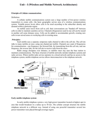
  • 1. Unit – I (Wireless and Mobile Network Architecture) Principle of Cellular communication: Definition: A cellular mobile communications system uses a large number of low-power wireless transmitters to create cells—the basic geographic service area of a wireless communications system. Variable power levels allow cells to be sized according to the subscriber density and demand within a particular region. As mobile users travel from cell to cell, their conversations are "handed off" between cells in order to maintain seamless service. Channels (frequencies) used in one cell can be reused in another cell some distance away. Cells can be added to accommodate growth, creating new cells in non served areas or overlaying cells in existing areas. Principles: Each mobile uses a separate, temporary radio channel to talk to the cell site. The cell site talks to many mobiles at once, using one channel per mobile. Channels use a pair of frequencies for communication—one frequency, the forward link, for transmitting from the cell site, and one frequency, the reverse link, for the cell site to receive calls from the users. Radio energy dissipates over distance, so mobiles must stay near the base station to maintain communications. The basic structure of mobile networks include telephone systems and radio services. Where mobile radio service operates in a closed network and has no access to the telephone system, mobile telephone service allows interconnection to the telephone network. Early mobile telephone system: In early mobile telephone system s very high power transmitter located at highest spot in area that would broadcast in a radius up to 50 km .The cellular concept structure the mobile telephone network in a different way. Instead of using one powerful transmitter several low power transmitter were placed through coverage region.
  • 2. For example dividing metro Politian region into one hundred different areas with low power transmitter using twelve conversations each. With this system capacity increased from 12 conversation from one powerful transmitter to twelve hundred conversation using hundred low power transmitters. Cellular system Architecture: The amount of frequency spectrum available for current mobile cellular coverage was limited and because of this efficient use of spectrum was needed . With this aim in mind in cellular telephony the rural and urban region are divided into several areas according to some specific guidelines. Cells: The cell is basic geographic unit of cellular system. The term cell come from honeycomb shape of areas into coverage regions are divided. Cells are represented as hexagons shape. Each cell shape is depends on landscape area. Because of the natural constraints and man made structure imposed, the true shape of the cell is not a perfect hexagon. CELL CLUSTER: Cell cluster is group of cell. No frequency channels are used within the cluster.
  • 3. Frequency Reuse: Because only a small number of radio channel frequencies were available formobile systems, engineers had to find a way to reuse radio channels in order to carry more than one conversation at a time. The solution the industry adopted was called frequency planning or frequency reuse. Frequency reuse was implemented by restructuring the mobile telephone system architecture into the cellular concept. The concept of frequency reuse is based on assigning to each cell a group of radio channels used within a small geographic area. Cells are assigned a group of channels that is completely different from neighboring cells. The coverage area of cells are called the footprint. This footprint is limited by a boundary so that the same group of channels can be used in different cells that are far enough away from each other so that their frequencies do not interfere Cell Splitting: Unfortunately, economic considerations made the concept of creating fullsystems with many small areas impractical. To overcome this difficulty, system operators developed the idea of cell splitting. As a service area becomes full of users, this approach is used to split a single area into smaller ones. In this way, urban centers can be split into as many areas as necessary in order to provide acceptable service levels in heavy-traffic regions, while larger, less expensive cells can be used to cover remote rural regions
  • 4. Overview of 1G, 2G, 3G & 4G Technology 1G Wireless Technology: Developed in 1980s and completed in early 1990’s. 1G was old analog system and supported the 1 st generation of analog cell phones speed up to 2.4kbps. Allows users to make voice calls in 1 country. Poor Hand Off, Dropped Connections, Low Capacity and No security. Not Suitable for data application. Due to Limitations, European countries were quick to move GSM technology. 2G Wireless Technologies: 2G networks introduced Digital capabilities to wireless in early 1990s. High voice quality & basic data services like voice mail. Limited browsing. Circuit Switched Technology Increased Capacity and Strong security. Many 2G system uses TDMA and few uses CDMA . Digital systems Technology to increase capacity Speech compression; digital signal processing “Intelligent Network” concepts which Improve fraud prevention and adds new services There are a wide diversity of 2G systems. Four major 2G systems are currently in use. DAMPS (Digital AMPS now known as TDMA) CDMA (IS 95) introduced by Qualcomm in 1995 Global System for Mobile Communications (GSM) Most popular of the 2G networks. Personal Digital Cellular (PDC) , largely used in Japan. D-merits of 2G: Inefficient & Expensive provide very limited data rates due to circuit switched technology. Higher Capacity, Higher Data Transfer Rate & Global Roaming are the driving forces for behind next generation(2.5 & 3G). 2.5 G Wireless Technology: Migration From Circuit Switching in to Packet Switching. 10 times greater data rate than 2G Networks.Only Software Up-gradation Required form 2G Up to 2.5 G.Two leading 2.5 G Network Protocols are GPRS & CDMA 2000 1x. GPRS: Frequencies Range 900,1800 & 1900 MHz. Theoretical Data Rate 115 to 144 K bps. But realistic data transfer data rate 56 K bps. DMA 2000 1x (2.5 G) Data Through put 144 K bps. Frequencies ranges from 800 and 1900 MHz. 3 G Wireless Technology: Japan is the first country having introduced 3G nationally, and in Japan the transition to 3G is being largely completed during 2005/2006. Services include: Global roaming. Superior voice quality and video conference. Data always, add–on services (e-mail, personal organizer, etc.) Information for web surfing, music, news, corporate intranet, transportation service etc. Purchasing – on-line shopping / banking, ticketing, gambling, games, etc. 3G Networks are IP based . 3G Devices Support for multimedia content such as video streaming. Large, high–resolution screens high PDA . Integrated voice & data as in high-end smart high-phones. Transmission speeds from 125kbps to 2Mbps. In 2005, 3G was ready to live up to its performance in computer networking (WCDMA, WLAN and Bluetooth) and mobile devices area (cell phone and GPS) Packet switching. CDMA is used in many 3G system. Difference between CDMA and TDMA is shown in following figure. Same frequency band is used in CDMA where different frequency bank is used for every cell in TDMA.
  • 5. 4 G Wireless Technologies: 4G is a conceptual framework and a discussion point to address future needs of a high speed wireless network It offer both cellular and broadband multimedia services everywhere. Expected to emerged around 2012 – 2015. 4G is the short term for fourth-generation wireless. It is fourth- expected that end-to-end IP and high-quality streaming video end-to- high- will be among 4G's distinguishing features. A 4G system will be able to provide a comprehensive IP solution where voice, data and streamed multimedia can be given to the users on “Anytime Anywhere” basis and higher data rates than the previous generations. It will be a fully IP based integrated system capable of providing between 100 M bps to roaming mobile user and up to 1 G bps for stationary mobile user with premium quality and high security. OBJECTIVE: 4G is being developed to accommodate the Quality of Service (QOS) and rate requirements set by forth coming applications like 1. MMS (Multimedia Messaging Service 2. Wireless Broadband Service 3. Video Chat 4. Mobile TV 5. Digital Video Broadcasting 6. High Network Capacity 7. Data Rate of 100 M bps for mobile and 1 G bps while stationary . 8. Smooth hand off across heterogeneous network.. 9. Global Roaming across multiple networks with Low cost APPLIICATIONS The applications of 4G are called “KILLER Applications” as it is going to bring revolution in the internet world. High Speed Data Rate due to which a movie can be downloaded in 2 to 3 minutes. More Security, Video Conferencing, Higher Bandwidth, Global Roaming. 4G will bring almost perfect real world wireless or called “WWWW: World Wide Wireless Web.
  • 6. GSM System Overview GSM: Global System for Mobile (GSM) is a second generation cellular standard developed to cater voice services and data delivery using digital modulation. Developed by Group Special Mobile (founded 1982) which was an initiative of CEPT? (Conference of European Post and Telecommunication) aims to replace the incompatible analog system. More than 1300 million subscribers in world and 45 million subscribers in India. GSM Services: 1) Tele- Services 2) Bearer or Data Services 3) Supplementary services Telecommunication services that enable voice communication via mobile phones. Bearer services include various data services for information transfer between GSM and other networks like PSTN, ISDN etc at rates from 300 to 9600 bps Short Message Service (SMS) up to 160 character alphanumeric data transmission to/from the mobile terminal. Unified Messaging Services(UMS) includes, fax, Voice mailbox and Electronic mail Supplementary Services includes Call related services: Call Waiting- Notification of an incoming call while on the handset, Call Hold- Put a caller on hold to take another call Call Barring- All calls, outgoing calls, or incoming calls Call Forwarding- Calls can be sent to various numbers defined by the user Multiparty Call Conferencing - Link multiple calls together GSM Architecture: GSM Architecture a mobile station communicates with a base station system(BSS) through the radio interface. The BSS is connected to the network and switching subsystem (NSS) by communicating with a mobile switching center ( MSC) using A-interface. Mobile Station (MS): ď‚· Mobile Equipment (ME) ď‚· Subscriber Identity Module (SIM) Base Station Subsystem (BSS): ď‚· Base Transceiver Station (BTS) ď‚· Base Station Controller (BSC) Network Switching Subsystem(NSS): ď‚· Mobile Switching Center (MSC) ď‚· Home Location Register (HLR) ď‚· Visitor Location Register (VLR) ď‚· Authentication Center (AUC) ď‚· Equipment Identity Register (EIR
  • 7. (GSM Architecture) Mobile Station (MS): The Mobile Station is made up of two entities: 1. Mobile Equipment (ME) 2. Subscriber Identity Module (SIM) Mobile Station (MS) Mobile Equipment is Portable, vehicle mounted, hand held device uniquely identified by an IMEI International Mobile Equipment Identity. Performs Voice and data transmission, Monitoring power and signal quality of surrounding cells for optimum handover .Power level : 0.8W – 20 W & 160 character long SMS.
  • 8. Subscriber Identity Module (SIM): Smart card contains the International Mobile Subscriber Identity (IMSI) . Allows user to send and receive calls and receive other subscribed services. The SIM is protected by a personal identification number (PIN) between four to eight digit in length. The PIN is initially loaded by the network operator at the time of subscription. This PIN can be deactivated or changed by the user. To use the MS , the user is asked to enter the PIN. If number is not entered correctly in three attempts , the SIM get blocked. To unblock the SIM the user is asked to enter eight digit PIN unblocking key (PUK). Base Station Subsystem (BSS): Base Station Subsystem is composed of two parts that communicate across the standardized Abis interface allowing operation between components. 1. Base Transceiver Station (BTS) 2. Base Station Controller (BSC) Base Transceiver Station (BTS): The BTS contain transmitters, receiver and signaling equipment specific to the radio interface. An important part of the BTS is the Transcoder/Adapter Rate Unit (TRAU) that carries out GSM specific speech encoding and decoding as well as rate adaptation in data transmission. Base Station Controller (BSC): The BSC is responsible for the switching functions in the BSS and is in turn connected to to an MSC in the NSS. The BSC supports radio channel allocation/release of resources and hand-off management within BSS. Handles call set up. Network Switching Subsystem (NSS): The NSS supports the switching functions, subscribers profiles and mobility management. Mobile Switching Center (MSC): The basic switching function in NSS is performed by MSC. The MSC also communicates to other network elements external to GSM. ď‚· Heart of the network ď‚· Manages communication between GSM and other networks ď‚· Call setup function and basic switching ď‚· Call routing ď‚· Billing information and collection ď‚· Mobility management ď‚· Registration ď‚· Location Updating ď‚· Inter BSS and inter MSC call hand-off MSC does gateway function while its customer roams to other network by using HLR/VLR. Home Location Registers (HLR): The current location of mobile user is usually maintained by the HLR. Permanent database about mobile subscribers contains IMSI, MSISDN, prepaid/postpaid, roaming restrictions, supplementary services.
  • 9. Visitor Location Registers (VLR): When mobile user moves from the home system to a visited system, its location is registered at the VLR of visited system. ď‚· Temporary database which updates whenever new MS enters its area, by HLR database - Controls those mobiles roaming in its area ď‚· Reduces number of queries to HLR Authentication Center (AUC): - Protects against intruders in air interface - Maintains authentication keys and algorithms - Generally associated with HLR Equipment Identity Register (EIR): Database that is used to track handsets using the IMEI (International Mobile Equipment Identity) Frequency used from Mobile to BTS (up-link): 1710-1785 MHz and from BTS to Mobile (down-link) 1805-1880 MHz.
  • 10. Hand off Management PCS system architecture The mobile service area is covered by a set of base stations (BS's), which are responsible for relaying the calls to and from the mobile stations (MS) located in their coverage areas (or cells). The BSs are connected to mobile switching centers (MSC) by land links. There are two aspects of mobility in a PCS network: ď‚· Hand-off ď‚· Roaming Hand off: When a mobile user is engaged in conversation, the MS is connected to a BS via a radio link. If the mobile user moves to the coverage area of another BS, the radio link to the old BS is eventually disconnected, and a radio link to the new BS should be established to continue the conversation. This process is variously referred to as automatic link transfer, handover, or hand- off. Roaming: When a mobile user moves from one PCS system (e.g., the system in New York City) to another (e.g., the system in Los Angeles), the system should be informed of the current location of the user. Otherwise, it would be impossible to deliver the services to the mobile user. To support mobility management, protocols such as EIA/TIA Interim Standard 41 (IS-41 or ANSI-
  • 11. 41) or Global System for Mobile Communications (GSM) Mobile Application Part (MAP) have been defined for PCS networks. Three strategies have been proposed to detect the need for hand off: ď‚· Mobile-controlled hand off (MCHO) ď‚· Network-controlled hand off (NCHO) ď‚· Mobile-assisted hand off (MAHO) Mobile-Controlled Hand off (MCHO): The MS continuously monitors the signals of the surrounding BS's and initiates the hand- off process when some hand-off criteria are met. MCHO is used in DECT and PACS. Network-Controlled Hand-off (NCHO): The surrounding BS's measure the signal from the MS, and the network initiates the hand-off process when some hand-off criteria are met. NCHO is used in CT-2 Plus and AMPS. Mobile-assisted hand-off (MAHO): The network asks the MS to measure the signal from the surrounding BS's. The network makes the hand-off decision based on reports from the MS. MAHO is used in GSM and IS-95 CDMA. Two types of hand off are there in PCS network. The BS's involved in the hand off may be connected to the same MSC (inter-cell hand off or inter-BS hand off). The BS's involved in the hand off may be connected to two different MSC (inter-system hand off or inter- MSC hand off ).
  • 12. Inter-BS Hand off: The new and the old BS's are connected to the same MSC. Assume that the need for hand off is detected by the MS, the following steps are taken: ď‚· The MS momentarily suspends conversation and initiates the hand-off procedure by signaling on an idle (currently free) channel in the new BS. Then it resumes the conversation on the old BS. ď‚· Upon receipt of the signal, the MSC transfers the encryption information to the selected idle channel of the new BS and sets up the new conversation path to the MS through that channel. The switch bridges the new path with the old path and informs the MS to transfer from the old channel to the new channel. ď‚· After the MS has been transferred to the new BS, it signals the network, and resumes conversation using the new channel. ď‚· Upon receipt of the hand off completion signal, the network removes the bridge from the path and releases resources associated with the old channel. This hand off procedure is used with the mobile-controlled hand off strategy. For the network-controlled hand off strategy, all hand off signaling messages are exchanged between the MS and the old BS though the failing link. The whole process must be completed as quickly as possible, to ensure that the new link is established before the old link fails. If the new BS does not have an idle channel, the hand-off call may be dropped (or forced to terminate).The forced termination probability is an important criterion in the performance evaluation of a PCS network.
  • 13. Most PCS networks handle a hand-off in the same manner as a new call attempt. That is, if no channel is available, the hand-off is blocked and the call is held on the current channel in the old cell until the call is completed or when the failing link is no longer available. This is referred to as the non-prioritized scheme. channel assignment schemes: To reduce forced termination and to promote call completion, three channel assignment schemes have been proposed: ď‚· Reserved channel scheme. ď‚· Queuing priority scheme. ď‚· Sub-rating scheme. Reserved channel scheme: Similar to the non-prioritized scheme, except that some channels in each BS are reserved for hand-off calls. Queuing priority scheme: If no channel is available in the new BS during hand-off, the new BS buffers the hand-off request in a waiting queue. The MS continues to use the channel with the old BS until either a channel in the new BS becomes available (and the hand-off call is connected) or the MS moves out of the hand-off area (and the call is forced to terminate). Sub-rating scheme: Sub-rating means an occupied full-rate channel is temporarily divided into two channels at half the original rate. one to serve the existing call and the other to serve the hand-off request. When occupied channels are released, the sub-rated channels are immediately switched back to full-rate channels. These hand off schemes can significantly reduce the probability of forced termination as well as the probability of call in completion (new call blocking plus hand off call forced termination).
  • 14. Inter-system Hand off In inter-system hand-off, the new and old BS's are connected to two different MSC. We trace the inter-system hand-off procedure of IS-41, where network-controlled hand-off (NCHO) is assumed. In this figure, a communicating mobile user moves out of the BS served by MSC A and enters the area covered by MSC B. Inter-system hand-off requires the following steps: ď‚· MSC A requests MSC B to perform hand-off measurements on the call in progress. MSC B then selects a candidate BS2, BS2, and interrogates it for signal quality parameters on the call in progress. MSC B returns the signal quality parameter values, along with other relevant information, to MSC A. ď‚· MSC A checks if the MS has made too many hand-offs recently (this is to avoid, for example, numerous hand-offs between BS1 and BS2 a where the MS is moving within the overlapped area) or if inter-system trunks are not available. If so, MSC A exits the procedure. Otherwise, MSC A asks MSC B to set up a voice channel. Assuming that a voice channel is available in BS2, MSC B instructs MSC A to start the radio link transfer. ď‚· MSC A sends the MS a hand-off order. The MS synchronizes to BS2. After the MS is Connected to BS2, MSC B informs MSC A that the hand-off is successful. MSC A then connects the call path (trunk) to MSC B and completes the hand-off procedure. In this inter-system hand-off process, MSC A is referred to as the anchor MSC, and is always in the call path before and after the hand-off, as illustrated in the four cases in Figure
  • 15. If the MS moves back to MSC A again, the connection between MSC A and MSC B is removed (hand-off backward). If the MS moves to the third MSC C, then MSC B will be in the call path (hand-off to third). Note that when the MS moves to the third MSC, the second MSC may be removed from the call path. That is, the link between MSC B and MSC A is disconnected, and MSC C connects to MSC A directly. This process is called path minimization.
  • 16. Roaming Management Two basic operations in roaming management are registration (or location update), the process whereby an MS informs the system of its current location, and location tracking, the process during which the system locates the MS. Location tracking is required when the network attempts to deliver a call to the mobile user. Roaming Management The roaming management strategies proposed in the IS-41 and GSM MAP standards are two- level strategies in that they use a two-tier system of home and visited databases. Home Location Register (HLR) When a user subscribes to the services of a PCS network, a record is created in the system's database, called the home location register (HLR). This is referred to as the home system of the mobile user. The HLR is a network database that stores and manages all mobile subscriptions of a specific operator. Specifically, the HLR is the location register to which an MS identity is assigned for record purposes, such as directory number, profile information, current location, and validation period. Visitor Location Register (VLR): When the mobile user visits a PCS network other than the home system, a temporary record for the mobile user is created in the visitor location register (VLR) of the visited system. The VLR temporarily stores subscription information for the visiting subscribers so that the corresponding MSC can provide service. In other words, the VLR is the "other" location register used to retrieve information for handling calls to or from a visiting mobile user. Registration Procedure : 1. Suppose that the home system of a mobile user is in Morristown. When the mobile user moves from one visited system (e.g., New York City) to another (e.g., Los Angeles), it must register in the VLR of the new visited system. 2. The new VLR informs the mobile user's HLR of the person's current location-the address of the new VLR. The HLR sends an acknowledgment, which includes the MS's profile, to the new VLR.
  • 17. 3. The new VLR informs the MS of the successful registration. 4. After step 2, the HLR also sends a de registration message to cancel the obsolete location record of the MS in the old VLR. The old VLR acknowledges the de registration. Call delivery procedure: ď‚· To originate a call, the MS first contacts the MSC in the visited PCS network. The call request is forwarded to the VLR for approval. If the call is accepted, the MSC sets up the call to the called party following the standard PSTN call setup procedure. ď‚· If a wire line phone attempts to call a mobile subscriber, the call is forwarded to a switch, called the originating switch in the PSTN, which queries the HLR to find the current VLR of the MS. The HLR queries the VLR in which the MS resides to get a rout able address. ď‚· If the originating switch is not capable of querying the HLR (i.e., it is not equipped to support mobility), the call is routed through the PSTN to the subscriber's gateway MSC, which queries the HLR to determine the current VLR serving the MS. ď‚· The VLR returns the rout-able address to the originating switch through the HLR. ď‚· Based on the rout-able address, a trunk (voice circuit) is set up from the originating switch to the MS through the visited MSC.
  • 18. Network Signaling Types of Signaling : ď‚· Channel Associated Signaling (CAS) ď‚· Common Channel Signaling (CCS) Channel Associated Signaling (CAS) : Used for In-Band Signaling where Signaling is transmitted in the same frequency band as used by voice. Voice path is established when the call setup is complete, using the same path that the call setup signals used. Common channel signaling ( CCS ): It is a signaling method that provides control and management of function in the telephone network. CCS consist of supervisory functions, addressing and call information. Signaling System Number (SS7) is a form of Common Channel Signaling. CCS uses out of band signaling network to carry the signaling messages. Signaling System No. 7: Signaling between a PCS network and the PSTN is achieved by the SS7 network. Figure shows the network element that are involved in the interconnection between a PCS network and the PSTN. In the figure , the dashed lines represents the signaling links and the solid line represents a trunk. The SS7 consist of three distinct components. Service switching point (SSP) : It is a switch in PSTN interconnected by SS7 signaling links. The SSP performs call processing which contains originating and termination of call at specified node. A local SSP in PSTN is refer-ed as end office or central office. An SSP in PCS network is called as Mobile Switching Center.
  • 19. Signal Transfer Point ( STP ): It is also a switch that relays SS7 message between network switches and databases. Based on the address mentioned in SS7 message, the STP route the message to the correct outgoing signaling link. Service Control Point (SCP): It contains the database for providing enhanced services. An SCP accepts queries from an SSP and returns the requested information to the SSP. In mobile network an SCP may contain an HLR or VLR. In this network, the trunk (Voice circuit) that connects SSP's of PSTN and PCS network to carry the user data or voice transmission. The signaling link connects SCP's to STPs and STPs to SSPs. The SCP and SSP are connected indirectly through STP. There are six types of SS7 signaling links. Two types, the A-link and D-link are shown in figure. Each signal switching point and service switch point will have minimum one link to each STP. This signaling link is referred to as access link (A-link). Signaling link that connect STPs of different network ( e.g PCS and PSTN in our example). Are called diagonal links (D-links). SS7 Protocol Stack: The SS7 protocol layers and the corresponding OSI layers are shown in following figure. The message transfer part.: It consist of three levels corresponding to the OSI physical, data link and network layer respectively. The MTP level1 defines the physical and functional characteristics of the signaling links that connects SS7 different components. The MTP level 2 provides reliable transfer of signaling message between two directly connected signaling points. The MTP level 3 provides the functions and procedures related to the message routing and network management. Signaling Connection Control Part (SCCP ): SCCP provides additional functions such as global title translation ( GTT) to the MTP. The MTP utilizes GTT to transfer non circuit related information such as PCS registration and cancellation. TCAP: Transaction capability application part provides capability to exchange information between applications using non circuit related signaling. OM &AP:
  • 20. The operations, Maintenance and Administration part (OMAP) is an application of TCAP that provides operation system function for billing, accounting, and mobile equipment identification and HLR measurements. Whereas Tariff management, network management is the part of administration. Maintenance includes the maintenance of PCS network component such as HLR, VLR, AUC and EIR. MAP: Mobile application part (MAP) is also an application of TCAP. Both IS-41 and GSM MAP standards are implemented at this layer. IS-41 based and GSM based MAP protocol are used for network management purpose.
  • 21. Mobile Devices and Mobile Operating Systems An Overview Windows CE: One of Microsoft’s products. Windows CE OS was designed for Handheld PC devices (between PDAs and laptops). It focuses on the enterprise market for mobile enterprise systems Basic functional features. Enable multitasking - allow the user to work on one application which another is executing in the background. Include many familiar applications, such as PocketWord, PocketExcel, PocketOutlook, and Pocket Internet Explorer. Built-in multimedia capabilities for both audio and video. History of Windows CE: • Back in 1995, Microsoft released the first version of Windows CE. It has very limited success. • In 1998, Microsoft released Windows CE 2.x for the PDA market. It was confident that it is PalmPilot killer. This proved not to be the case. • In 2000, Microsoft released Windows CE 3.0 when the PDA market was becoming more attractive to enterprises for line-of-business applications. • In 2001, Microsoft announced another version of the Windows CE family: Windows CE.NET 4.0. – This version fits into Microsoft’s overall .NET strategy by allowing developers to use the full suite of Microsoft tools, including Visual C++ and other updated Microsoft office products and Internet Explorer. – Windows CE .NET added built-in wireless capabilities, including broad support for WANS, LANs, and PANs. • In the fall of 2002, Windows CE .NET version 4.1 was released. This version added support for IPv6 (the latest version of Internet Protocol), as well as integrated speech recognition. Why did Windows CE3.0 succeed? • It comes with many familiar applications, such as PocketWord. • It provides a scaled-down version of Win32 application programming interface (API), allowing developers to quickly refit existing Window applications for Windows CE 3.0-based devices. • Provide enhanced support for real-time functionality made to the OS kernel. This improves the performance of Windows CE 3.0 dramatically over Windows CE 2.x. Comparisons of Windows CE versions: ----------------------------------------------------------------------------------------------------------------- Versions Year Processors Internet Wireless Multimedia Browser Capability Support ----------------------------------------------------------------------------------------------------------------- CE 2.12 1998 ARM, MIPS IE 4.0 IrDA No PowerPC, SHx x86 CE 3.0 2000 ARM, MIPS, IE 4.0 IrDA Yes CE .NET 2002 X-Scale, ARM I.E. 5.5 Bluetooth Yes 802.11x Media Sense OBEX
  • 22. An Overview of Palm OS It is designed by Palm Computer for PDAs. It has been experienced tremendous success in the PDA’s consumer market. History of Palm OS: • In early 2000 (by IDC, June 2000), Palm established itself as the market leader in PDAs, capturing nearly 75% of the worldwide mobile OS market. • In the early days of PDA application development, people chose Palm OS as a deployment platform because it is available and many employees were familiar with it. • Due to the limitation of its early versions, people found that it was unsuitable for many of application tasks. This causes some problems in positioning itself at a dominant position in the enterprise market. • Late of 2000, Palm separating the PDA hardware and Palm OS as two different divisions and started licensing Palm OS to third-party device manufactures, such as Handspring, IBM, Symbol, and Sony. • Palm OS 5.0, 6.0 and Palm i705 released new features for the enterprise applications. Basic functional features: • Prior to the release of version 5.0, Palm OS only support single-tasking • With version 5.0, Palm OS introduced some multi-tasking capabilities. • Provide two kinds of local databases in a flat-file format: – Record database – store and manage application data, such as contact list – Resource database – store and manage the application code and user interface objects. • Meanwhile, Palm OS 5.0 provides some extra features: – Move to the ARM series of processors -> increase its performance greatly. – Move CMPE- Additional security for encrypting private data – New wireless capabilities for earlier access to the Internet and email systems • Palm OS i750 include wireless support for always-on wireless networks, Bluetooth, and clip- on modems.
  • 23. An Overview of Symbian OS • Symbian OS is an operating system developed for exclusively for mobile devices. • Symbian OS is designed for 32-bit CPUs based on 190MHZ and 206MHZ StrongARM CPUs with some on ARM9. • Symbian OS gained its popularity in the mobile phone sector. • It is created by Symbain, which is a joint venture of Nokia, Ericsson, Motorola, and Matsushita. This partnership was to create a standard OS for smart phones and PDAs . • Symbian OS is the name assigned to the lastest version of the EPOC os. Versions prior to 6.0 are called EPOC, while later versions are called Symbian OS. History of Symbian OS: • In June 1999, EPOC version 5 started shipping. It contained support for devices based on a 640x240 screen resolution, with pen and keyboard capabilities. • In 2000, Symbian OS 6.0 was released. Its design goal is to bring together various forms of communication protocols, such as TCP/IP, WAP, GSM, Bluethooth, IrDa, as well as serial connections. • In 2002, Symbian OS version 7.0 was released. This version is designed for the unique requirements of advanced 2G, 2.5G, and 3G mobile phones. Basic Features: • Basic operating system features supporting 32-bit CPUs, memory, system RAM, I/O devices, such as keyboards, disks (memory-card), RS232 and connection to PC, an infrared port, and bluetooth for wireless transfer of data between Symbian OS and others, such as PDAs. • Supporting communication protocols, TCP/IP, WAP(1.2.1), GSM, Bluetooth, IrDa and serial connections. • Allow C++/Java (Java applets)–based applications to be executed. • Full-strength security using HTTPS, WTLS, and SSL. • Enhanced multimedia capabilities • Over-the-air data synchronization using SyncML • Supporting advanced messaging, including NMS< EMS, and SMS • Providing a complete suite of application engines for contacts, schedules, Web browsing and system control Process boundaries of Symbian:
  • 24. Basics of Symbian OS: The Kernel is a core of Symbian OS. Manages the machine’s hardware resources such as system RAM, and hardware devices. Provides and controls the way all other software components can access these resources. • Uses hardware-supported privilege to gain access to the resources. Application is a program with a user interface. Each application runs in a separate process with its own virtual address space. Symbian OS implements preemptive multitasking so that it can run multiple applications and servers simultaneously. The Process is a fundamental unit of protection in Symbian OS. Each process has its own address space. The virtual address used by programs executing in that process are translated into physical addresses in the machine’s ROM and RAM. The translation is managed by memory management unit (MMU), so that the read-only memory is shared. The Thread is the fundamental unit of execution in Symbian OS. A process may has one or more threads. Each thread executes independently of the others, but share the same address space. Threads are preemptively scheduled by the Symbian OS kernel. The highestt-priority thread that is eligible to run at a given time is run by the kernel. A thread may have the following status: Ă  run, scheduled, suspended (waiting for events), and resume.