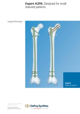
SlideShare a Scribd company logo
1 of 76
Download to read offline
Expert
Nailing System
Expert A2FN. Designed for small
statured patients.
Surgical Technique
This publication is not intended for
distribution in the USA.
Instruments and implants
approved by the AO Foundation.
Image intensifier control
This description alone does not provide sufficient background for direct use
of DePuy Synthes products. Instruction by a surgeon experienced in handling
these products is highly recommended.
Processing, Reprocessing, Care and Maintenance
For general guidelines, function control and dismantling of ­
multi-part
instruments, as well as processing guidelines for ­
implants, please contact your
local sales representative or refer to:
http://emea.depuysynthes.com/hcp/reprocessing-care-maintenance
For general information about reprocessing, care and maintenance of
Synthes reusable devices, instrument trays and cases, as well as processing of
Synthes non-sterile implants, please consult the Important Information leaflet
(SE_023827) or refer to:
http://emea.depuysynthes.com/hcp/reprocessing-care-maintenance
Expert A2FN  Surgical Technique  DePuy Synthes    1
Table of Contents
Introduction	 Expert A2FN 2
AO Principles  4
Indications and Contraindications 5
Surgical Technique	 Clinical Cases 6
Preoperative Planning 8
Open Femur  9
Insert Nail 20
Proximal Locking – Standard 27
Proximal Locking – Recon 35
Distal Locking 41
Insert End Cap 48
Implant Removal 49
Product Information	Nails 58
Locking Implants 61
Standard Instruments  64
Vario Case 69
Bibliography	 70
MRI Information	 71
Expert A2FN. Designed for small
statured patients.
Advanced anatomical design
One concept, one system
Modulated intramedullary system with streamlined
instrumentation
– Easy insertion and extraction
– 
Flattened lateral side reduces
impingement of the lateral cortex
and decreases medialization
Multiple locking options
Standard locking
– 
Femoral shaft fractures
(except subtrochanteric fractures)
Expert Nailing System
Recon locking
– Subtrochanteric fractures
– 
Combined femoral shaft and neck
fractures (ipsilateral)
Cannulated end caps
– Easy insertion and extraction
– Stardrive recess
Multiple locking options
– 
High stability through
multiplanar screws
– Antirotational stability
– Distal dynamization option
1
4
2
3
4_Priciples_03.pdf 1 05.07.12 12:08
4 DePuy Synthes Expert Lateral Femoral Nail Surgical Technique
AO PRINCIPLES
In 1958, the AO formulated four basic principles, which
have become the guidelines for internal fixation1,2
.
1
Müller ME, M Allgöwer, R Schneider, H Willenegger. Manual of Internal
Fixation. 3rd ed. Berlin Heidelberg New York: Springer. 1991.
2
Rüedi TP, RE Buckley, CG Moran. AO Principles of Fracture Management.
2nd ed. Stuttgart, New York: Thieme. 2007.
Anatomic reduction
Fracture reduction and fixation to
restore anatomical relationships.
Early, active mobilization
Early and safe mobilization and
rehabilitation of the injured part
and the patient as a whole.
Stable fixation
Fracture fixation providing abso-
lute or relative stability, as
required by the patient, the injury,
and the personality of the
fracture.
Preservation of blood supply
Preservation of the blood supply
to soft tissues and bone by
gentle reduction techniques and
careful handling.
4    DePuy Synthes  Expert A2FN  Surgical Technique
AO Principles
1
 
Müller ME, Allgöwer M, Schneider R, Willenegger H. Manual of Internal Fixation.
3rd
ed. Berlin, Heidelberg, New York: Springer. 1991.
2
 
Rüedi TP, Buckley RE, Moran CG. AO Principles of Fracture Management. 2nd
ed.
Stuttgart, New York: Thieme. 2007.
Stable fixation
Fracture fixation providing absolute
or relative stability, as required by the
­
patient, the injury, and the personality
of the fracture.
Anatomic reduction
Fracture reduction and fixation
to restore anatomical relationships.
Early, active mobilization
Early and safe mobilization and
rehabilitation of the injured part and
the patient as a whole.
Preservation of blood supply
Preservation of the blood supply
to soft tissues and bone by gentle
reduction techniques and careful
handling.
In 1958, the AO formulated four basic principles, which have
become the guidelines for internal fixation1,2
.
Expert A2FN  Surgical Technique  DePuy Synthes    5
Recon Locking Indications:
The Expert A2FN with recon locking is indicated for fractures
in the femoral shaft in case of combination with femoral
neck fractures:
32-A/B/C combined with 31-B (double ipsilateral fractures)
Additionally the Expert A2FN is indicated for fractures in the
subtrochanteric section:
32-A [1–3].1, 32-B [1–3].1, and 32-C [1–3].1
Contraindications
– Isolated femoral neck fractures
– Supracondylar fractures (localisation 32)
– Intertrochanteric fractures
– Pertrochanteric fractures
Standard Locking Indications:
The Expert A2FN with standard locking is indicated for
fractures in the femoral shaft:
32-A/B/C (except subtrochanteric fractures 32-A [1–3].1,
32-B [1–3].1, and 32-C [1–3].1)
Indications and Contraindications
6    DePuy Synthes  Expert A2FN  Surgical Technique
Clinical Cases
Case 1 – Standard locking
55 year old female
Fracture (AO 32-A)
postoperative
preoperative
Expert A2FN  Surgical Technique  DePuy Synthes    7
Case 2 – Recon locking
66 year old male
Ipsilateral femoral neck and shaft
fractures
preoperative
postoperative
8    DePuy Synthes  Expert A2FN  Surgical Technique
Preoperative Planning
Use the preoperative planner template for the ­
Expert A2FN
(034.000.535) to estimate nail ­
diameter and length.
To estimate the nail diameter, place the template on the
­
lateral x-ray of the uninjured femur and measure the
diameter of the medullary canal at the narrowest part that
will contain the nail.
To estimate the nail length, place the template on the
AP x-ray of the uninjured femur and select the appropriate
nail length based on patient anatomy.
When selecting the nail size, consider canal diameter, frac-
ture pattern, patient anatomy and post-operative protocol.
Expert A2FN  Surgical Technique  DePuy Synthes    9
Open Femur
1
Position patient
Position the patient supine on a fracture or radiolucent oper-
ating table. Position the C-arm to allow visualization of the
proximal femur, the fracture and the distal femur in both AP
and lateral planes.
Alternatively, the patient can be positioned supine with the
injured leg adducted or in the lateral decubitus position.
2
Reduce fracture
Perform closed reduction manually by axial traction under
image intensifier control. The use of the large distractor may
be appropriate in certain circumstances (refer to the surgical
technique 036.000.038).
11    DePuy Synthes  Expert A2FN  Surgical Technique
Open Femur
3
Confirm nail length and diameter
Instruments
03.010.020	 Radiographic Ruler for Expert Femoral
Nails
03.010.023	 Radiographic Ruler for Nail Diameters
	 for Expert Femoral Nails, length 365 mm
The required nail length must be determined after reduction
of the femoral fracture.
Position the C-arm for an AP view of the proximal femur.
With long forceps, hold the ruler alongside the lateral thigh,
parallel to and at the same level as the femur. Adjust the
ruler until the proximal end is at the desired nail insertion
position.
Mark the skin at the proximal end of the ruler.
Move the C-arm to the distal femur. Align the proximal end
of the radiographic ruler to the skin mark, and take an AP
image of the distal femur. Verify fracture reduction going
from proximal to the fracture to distal.
Read nail length directly from the ruler image, selecting the
measurement at or just proximal to the epiphyseal scar, or at
the chosen insertion position.
Notes:
–
– It is recommended that all fractures are treated with the
longest nail possible, taking into account patient anatomy
or a previous implant.
–
– Compression (with the conventional backstroke tech-
nique*) or dynamisation must be taken into account when
determining the nail length. A shorter nail should be cho-
sen when back-hammering or dynamisation is planned for
the procedure (the dynamic slot allows for 7 mm of move-
ment).
* 
Backstroke technique: with the hammer guide attached to the connector
and insertion handle (see Chapter 2 Insert Nail), light reverse hammer
blows may be used to compress the fracture; monitor reduction radiographically
Expert A2FN  Surgical Technique  DePuy Synthes    11
Alternatives
Determine the nail length by the procedure above on the
uninjured leg before draping (unsterile) or compare the
length of two identical SynReam reaming rods B 2.5 mm or
use the Depth Gauge for Medullary Nails in combination
with the Elongation Tube for Reaming Rods and the Syn-
Ream reaming rod B 2.5 mm, length 950 mm see RIA Surgi-
cal Technique.
Place the radiographic canal width estimator perpendicular
to the femur axis so that the round diameter gauge is lo-
cated over the isthmus. Select the nail diameter with which
the medullary canal-to-cortex transition is still visible on
both sides of the diameter gauge.
Notes:
–
– The ruler provides only an estimate of the canal diameter
as it is not at the same level as the femur.
–
– If the reamed technique is used, the diameter of the
largest medullary reamer applied must be 0.5 mm to
1.5 mm larger than the nail diameter.
11    DePuy Synthes  Expert A2FN  Surgical Technique
Open Femur
4
Approach
Palpate the posterior edge of the greater trochanter. Make
an 3 cm incision in line with the central axis of the intramed-
ullary canal in lateral view and 2 to 5 cm proximal to
the tip of the greater trochanter, depending on the anatomy
of the patient.
5
Determine entry point
The entry point is a determinant factor for the entire opera-
tion, especially for the optimal final position of the Expert
A2FN in the medullary canal.
In AP view, the entry point is at the tip of the greater tro-
chanter, approximately 5° lateral to the axis of the medullary
canal.
In lateral view the entry point is in line with the axis of the
intramedullary canal.
Note: To ensure a correct entry point the preoperative plan-
ner template for the Expert A2FN can be used
Expert A2FN  Surgical Technique  DePuy Synthes    11
6
Insert guide wire
Instruments
357.399	 Guide Wire B 3.2 mm, length 400 mm
393.105	 Universal Chuck, small, with T-Handle
03.010.357	 Protection Sleeve 17.0, for No. 03.010.366
and No. 03.010.367
03.010.358	 Multihole Drill Sleeve 17.0/3.2,
for No. 03.010.357
Secure the guide wire in the universal chuck.
Push the multihole drill sleeve into the protection sleeve and
insert the assembly over the guide wire through the incision
down to the bone if possible.
In the lateral view, verify whether the position of the guide
wire is straight and in the center of the medullary cavity.
Precaution: The correct entry point and angle are essential
for a successful result. To ensure the correct position of the
guide wire on the AP view, hold a sterile Expert A2FN nail
onto the femur and check radiograpically.
Option: percutaneous technique
Insert the assembly (protection sleeve and multihole drill
sleeve) through the incision and to the bone. Lightly mark
the insertion point at a 5° angle to the shaft axis in the
AP view. Insert the guide wire through the drill sleeve for
approx. 15 to 20 cm into the medullary canal. Check
the position in the AP and lateral views under the image
intensifier.
Remove the universal chuck.
Precaution: Dispose of the guide wire. Do not reuse.
11    DePuy Synthes  Expert A2FN  Surgical Technique
Open Femur
7
Option: realign guide wire
Instruments
357.399	 Guide Wire B 3.2 mm, length 400 mm
393.105	 Universal Chuck, small, with T-Handle
03.010.357	 Protection Sleeve 17.0, for No. 03.010.366
and No. 03.010.367
03.010.358	 Multihole Drill Sleeve 17.0/3.2,
	 for No. 03.010.357
Precaution: The position of the guide wire will be decisive
for the success of the next steps. If the position of the in-
serted guide wire is not optimal, it needs to be realigned or
repositioned. Slide the multihole drill sleeve over the guide
wire. Use the center of the multihole drill sleeve. Turn the
sleeve so that the new guide wire can be inserted at the cor-
rect entry point. Possible distances from the center are
4 mm, 5 mm and 6 mm.
Press the handle to secure the position of the multihole drill
sleeve. Secure a new guide wire in the universal chuck.
Press the multihole drill sleeve firmly to the bone and insert
the wire through the chosen hole of the multihole drill
sleeve.
Verify the correct position of the new guide wire in both
views. Remove the multihole drill sleeve and the first guide
wire.
Note: This multihole drill sleeve facilitates the realignment
of a guide wire as it uses the first wire as reference for the
positioning of the new one.
4 mm too lateral new guide-wire at the
correct position
Expert A2FN  Surgical Technique  DePuy Synthes    11
8
Open medullary canal with flexible drill bit
Instruments
357.399	 Guide Wire B 3.2 mm, length 400 mm
03.010.357	 Protection Sleeve 17.0, for No. 03.010.366
and No. 03.010.367
03.010.367	 Opening Drill Bit B 14.0 mm, cannulated,
	 flexible, length 206 mm, Stainless Steel
Remove the multihole drill sleeve (Protection sleeve stays in
situ).
Secure the flexible cannulated drill bit with the quick cou-
pling for DHS/DCS and guide it over the guide wire through
the protection sleeve to the bone. Drill the medullary canal
as far as the stop on the protection sleeve. Move the drill bit
continuously backwards and forwards to clear the debris
from the medullary cavity and to avoid jamming.
Use image intensifier control while drilling the medullary
canal.
Remove the drill bit and the guide wire. The Protection
sleeve remains in situ for the reaming of the medullary canal.
Precaution: After opening the proximal femur, dispose of
the guide wire. Do not reuse.
11    DePuy Synthes  Expert A2FN  Surgical Technique
Alternative: Open medullary canal with awl
Instruments
357.399	 Guide Wire B 3.2 mm, length 400 mm
03.010.365	Awl B 16.5/3.2 mm, cannulated
Remove the protection sleeve and the multihole drill sleeve.
Place the cannulated awl over the guide wire and open the
medullary canal. Use a twisting motion to advance the awl
to a depth of approximately 5 cm.
Note: The outer diameter of the awl is 3.5 mm bigger than
the proximal nail diameter to allow slight corrections of the
entry point.
Remove the awl and the guide wire.
Precaution:
–
– Refrain from hammering on the awl or applying excessive
force.
–
– After opening the proximal femur, dispose of the guide
wire. Do not reuse.
Open Femur
Expert A2FN  Surgical Technique  DePuy Synthes    11
9
Reduce fracture
Instrument
03.010.369	 Reduction Instrument for Medullary Nails
Perform closed reduction manually by axial traction under
image intensifier control. The use of the Reduction Instru-
ment for Medullary Nails may be appropriate in certain
circumstances.
Check fracture reduction under image intensifier.
11    DePuy Synthes  Expert A2FN  Surgical Technique
Open Femur
10
Option: ream medullary canal
Instrument
03.010.093	 Alternative: Rod Pusher for
Reaming Rod with Hexagonal
Screwdriver B 8.0 mm
Note: For the detailed reaming procedure, please consult
SynReam Surgical Technique.
If necessary, use a reaming system intended for femur ream-
ing procedures to enlarge the medullary femoral canal.
Check fracture reduction under image intensifier.
Insert reaming rod
Insert a 2.5 mm reaming rod into the medullary canal
until the desired insertion depth. The tip must be correctly
positioned in the medullary canal since it determines the fi-
nal distal position of the Expert A2FN. The use of the Reduc-
tion Instrument for Medullary Nails may be helpful in certain
circumstances.
Reaming
Starting with the smallest diameter reaming head, ream to a
diameter of 0.5 to 1.5 mm greater than the nail diameter.
Ream in 0.5 mm increments and advance the reamer with
steady, moderate pressure. Do not force the reamer. Partially
retract the reamer repeatedly to clear debris from the
medullary canal.
Use the holding forceps to retain the reaming rod while
reaming and to prevent it from rotating.
Expert A2FN  Surgical Technique  DePuy Synthes    11
Option
The length of the nail can be measured with two identical
reaming rods using the “overlapping method”.
Use the rod pusher to help retain the reaming rod during
reamer extraction.
Note: All Expert A2FN are cannulated and can be inserted
over the SynReam reaming rod. Reaming rod exchange is not
required.
22    DePuy Synthes  Expert A2FN  Surgical Technique
Insert Nail
1
Assemble insertion instruments
Instruments
03.010.351	 Insertion Handle for Expert A2FN
03.010.356	 Connection Screw, cannulated,
for Expert A2FN, for No. 03.010.351
03.010.092	 Screwdriver, hexagonal with spherical
head B 8.0 mm
Orientate the insertion handle laterally towards the nail and
match the notch of the handle to the nail (as is shown in the
figure on the right).
Place the connecting screw into the insertion handle and
thread it into the proximal nail end using the screwdriver.
Note: The anatomical design of the Expert A2FN requires
left and right nails. The nails are therefore labeled “ANTE-
RIOR” on both nails at proximal anterior end.
Precaution: Check that the connecting screw is correctly
tightened. Do not over-tighten.
Expert A2FN  Surgical Technique  DePuy Synthes    22
Optional instruments
Instruments
03.010.351	 Insertion Handle for Expert A2FN
03.010.356	 Connection Screw, cannulated,
for Expert A2FN, for No. 03.010.351
03.010.093 	 Rod Pusher for Reaming Rod
with Hexagonal Screwdriver B 8.0 mm
Optionally, slide the connecting screw onto the rod pusher.
Slide the assembly through the insertion handle and match
the notch of the handle to the nail. Tighten using the rod
pusher. Do not over-tighten.
22    DePuy Synthes  Expert A2FN  Surgical Technique
2
Insert nail
Instruments
03.010.351	 Insertion Handle for Expert A2FN
03.010.356	 Connection Screw, cannulated,
	 for Expert A2FN, for No. 03.010.351
Following correct coupling of insertion handle to the nail.
Orient the insertion handle anteriorly to insert the nail into
the medullary canal.
Use slight twisting motions to advance the nail.
Monitor nail passage across the fracture, and control in two
planes to avoid malalignment.
Insert the nail until it is at or below the femoral opening.
Check the final nail position in AP and lateral views.
The nail rotates approximately 90° during insertion. The in-
sertion handle rotates from anterior to lateral during inser-
tion of the last one-third of the nail length.
The Expert A2FN can be passed over the SynReam Reaming
Rod without use of the exchange tube.
If the nail does not rotate to the lateral position during
insertion, remove the nail and reinsert.
Precaution: Do not mount the aiming arm until the nail has
been completely inserted.
Insert Nail
Expert A2FN  Surgical Technique  DePuy Synthes    22
Optional instruments
Instruments
321.160	 Combination Wrench B 11.0 mm
03.010.047	 Connector, length 141 mm, for Insertion
Handle
03.010.364	 Combined Hammer 500 gr.,
for No. 03.010.170
03.010.170	 Hammer Guide
321.170	 Pin Wrench B 4.5 mm, length 120 mm
357.398	 Shaft, hexagonal Ø 8.0 mm, cannulated,
short, length 125 mm
If necessary, use light hammer blows to insert the nail. Slide
the connector into the medial grooves on the insertion han-
dle (use the lateral position only when the patient anatomy
requires this) and secure it in place using the combination
wrench.
Strike only on the connector.
Remove the connector after finishing the insertion.
Note: In case of insertion of the nail over the reaming rod
retighten the connection screw with the cannulated shaft
with 8 mm Hex.
22    DePuy Synthes  Expert A2FN  Surgical Technique
Optionally, the hammer guide can be threaded into the con-
nector and the hammer can be used as a slide hammer.
For this the hammer can be attached to the hammer guide
as shown in the pictures.
Remove the hammer guide and the connector.
Notes:
–
– If nail insertion is difficult, choose a smaller diameter nail
or ream the intramedullary canal to a larger diameter.
–
– Do not hammer directly onto the insertion handle. Espe-
cially after hammering, confirm that the nail is securely
connected to the insertion handle. Retighten if necessary.
Insert Nail
20 mm
15 mm
10 mm
5 mm
Expert A2FN  Surgical Technique  DePuy Synthes    22
3
Check proximal nail position
Instruments
03.010.350	 Aiming Arm for Expert A2FN
357.399	 Guide Wire B 3.2 mm, length 400 mm
Attach the aiming arm to the insertion handle and insert a
guide wire in the hole as shown in the illustration. The tip of
the guide wire indicates the exact proximal position of the
nail. Check final nail position under image intensification in
AP and lateral views.
Note: The distance between the markings on the insertion
handle is 5 mm and corresponds to the extensions of the end
caps. This feature can be used for overinsertion of the nail.
22    DePuy Synthes  Expert A2FN  Surgical Technique
Insert Nail
Compression
It is recommended to close fracture gaps in order to de-
crease the incidence of non-union or malunion.
The Expert A2FN offers two compression options.
Proximal:
–
– Active compression via compression screw
–
– Back stroke technique
–
– Dynamisation
Distal:
–
– Dynamisation
Note for proximal compression: If proximal compression
is planned, over-insert the nail to compensate for backstrik-
ing the nail, active compression with compression screw or
proximal dynamisation: the final position (after compression)
of the nail should be flush with the trochanteric cortex.
Note for distal dynamisation: If distal dynamisation is
planned, the tip of the nail will slide max. 9 mm distally. In
order to protect the articulating surface of the distal femur
this movement has to be taken into account when choosing
the length and insertion of the implant.
1
2
3
a b
c
Expert A2FN  Surgical Technique  DePuy Synthes    22
1
Locking options
There are three standard locking positions:
1.	The 120° antegrade locking option allows static locking.
	
2.	The dynamic locking option (DYN) corresponds to the
proximal position of the standard locking slot.
3.	The static locking option (STAT) corresponds to the distal
position of the standard locking slot.
Proximal standard locking options:
a.	For sufficient proximal static locking, it is suggested to
use the 120° antegrade locking option together with the
transverse static screw.
b.		
For immediate primary dynamisation, insert only one
proximal locking screw through the dynamic slot.
c.	 For secondary dynamisation use both the dynamic
and the 120° antegrade locking positions and remove the
120 degree locking when required.
Proximal Locking – Standard
22    DePuy Synthes  Expert A2FN  Surgical Technique
2
Insert trocar combination
Instruments
03.010.063	 Protection Sleeve 12.0/8.0, length 188 mm
03.010.065	 Drill Sleeve 8.0/4.2, for No. 03.010.063
03.010.070	Trocar B 4.2 mm, for No. 03.010.065
Confirm that the insertion handle is securely connected to
the nail. Attach the aiming arm to the insertion handle.
Insert the three-part trocar combination (protection sleeve,
drill sleeve and trocar) through the desired ML hole in the
aiming arm (STAT for static locking, DYN for dynamic lock-
ing). Make a stab incision and insert the trocar to the bone.
Remove the trocar.
Precaution: Do not exert forces on the aiming arm, protec-
tion sleeve, drill sleeves or drill bits. Such force may prevent
accurate targeting through the proximal locking holes and
damage the drill bits.
Proximal Locking – Standard
Expert A2FN  Surgical Technique  DePuy Synthes    22
3
Drill and determine locking screw length
Instruments
03.010.063	 Protection Sleeve 12.0/8.0, length 188 mm
03.010.065	 Drill Sleeve 8.0/4.2, for No. 03.010.063
03.010.061	 Drill Bit B 4.2 mm, calibrated,
	 length 340 mm, 3-flute,
	 for Quick Coupling, for No. 03.010.065
Drill through both cortices. Stop as soon as the tip of the drill
bit penetrates the far cortex.
Confirm drill bit position after drilling both cortices.
Ensure that the drill sleeve is pressed firmly to the lateral cor-
tex and read the measurement corresponding to the appro-
priate length of the locking screw at the back of the drill
sleeve. Remove the drill bit and the drill sleeve.
Note: A correct end position of the drill sleeve is important
in order to choose the correct length of the locking screw.
33    DePuy Synthes  Expert A2FN  Surgical Technique
Alternative instrument
Instruments
03.010.063	 Protection Sleeve 12.0/8.0, length 188 mm
03.010.072	 Depth Gauge for Locking Screws,
	 measuring range up to 110 mm,
	 for No. 03.010.063
After both cortices are drilled, remove the drill bit and the
drill sleeve.
Disassemble the depth gauge into 2 parts: the outer sleeve
and the measuring device with hook. Insert the measuring
device into the protection sleeve. Make sure that the hook
engages the far cortex and that the protection sleeve is
firmly pressed against the lateral cortex.
Read the measurement from the back of the protection
sleeve, which corresponds to the appropriate length of the
locking screw.
Note: A correct end position of the protection sleeve is
important in order to choose the correct length of the lock-
ing screw.
Proximal Locking – Standard
Expert A2FN  Surgical Technique  DePuy Synthes    33
4
Insert locking screws
Instruments
03.010.063	 Protection Sleeve 12.0/8.0, length 188 mm
03.010.107	 Screwdriver Stardrive, T25,
	 length 330 mm
Insert the appropriate locking screw through the protection
sleeve using the screwdriver Stardrive T25. Verify the position
of the locking screw under image intensifier.
The tip of the locking screw should not protrude more than
1 to 2 mm beyond the medial far cortex.
Note: A groove on the screwdriver provides a rough indica-
tion that the locking screw is fully inserted through the
sleeve.
If using 120° antegrade locking option, insert the trocar
combination through the hole labeled 120° on the insertion
handle.
33    DePuy Synthes  Expert A2FN  Surgical Technique
5
Active compression locking (optional)
For situations where the fracture gap needs compression
after nail insertion, compression of the fracture gap
can be accomplished without removing the insertion instru-
ments.
The Expert A2FN allows for a maximum compression of
7 mm. If more compression of the fracture gap is needed,
the conventional backstroke technique is recommended.
Note: Insert one proximal locking screw in the dynamic lock-
ing hole (DYN), refer to page 27 to 31 for details on inserting
this locking screw.
Proximal Locking – Standard
Expert A2FN  Surgical Technique  DePuy Synthes    33
6
Insert compression screw
Instruments
03.010.372	 Compression Screw, for Expert A2FN,
	 for 03.010.356
03.010.092	 Screwdriver, hexagonal with spherical
	head B 8.0 mm
Note: Distal locking must be performed prior to application
of compression. (see page 32)
Confirm that the nail is securely connected to the insertion
handle. Insert the compression screw through the connect-
ing screw and into the nail using the screwdriver.
The compression screw will contact the dynamic locking
screw. Advance the compression screw until the fracture gap
is reduced.
Monitor reduction under image intensification.
Each revolution of the compression screw corresponds to a
compression of 1 mm (maximum 7 mm).
Precaution: Do not over tighten the compression screw;
it may deform the locking screw.
33    DePuy Synthes  Expert A2FN  Surgical Technique
7
Monitor fracture
Control the fracture gap before, during and after the
compression procedure by monitoring on image intensifier.
8
Insert static locking screw (120 degree locking)
Remove the compression screw.
Insert second proximal locking screw in the 120 degree
locking hole, refer to steps 2 to 4 pages 28–31.
Proximal Locking – Standard
Expert A2FN  Surgical Technique  DePuy Synthes    33
1
Check nail position
Instruments
03.010.351	 Insertion Handle for Expert A2FN
03.010.350	 Aiming Arm for Expert A2FN
357.399	 Guide Wire B 3.2 mm, length 400 mm
03.010.353	 Protection Sleeve 11.5/8.5,
for Expert A2FN, yellow
03.010.354	 Drill Sleeve 8.5/3.2, for No. 03.010.353,
yellow
03.010.355	Trocar B 3.2 mm, for No. 03.010.354,
yellow
03.010.363	 Screwdriver Stardrive, T25,
length 480 mm, for Hip Screws
03.010.368	Reamer B 4.5/6.5 mm, length 450 mm,
for Hip Screws Expert A2FN
Confirm that the insertion handle is securely connected to
the nail and attach the aiming arm to the insertion handle.
In the AP view adjust the nail insertion depth to ensure that
the two recon screws can be optimally placed into the femo-
ral neck.
The position of the nail can be verified by placing two guide
wires onto the aiming arm and checking radiographically.
Proximal Locking – Recon
33    DePuy Synthes  Expert A2FN  Surgical Technique
To ensure the correct anteversion of the implant, insert an
additional guide wire into the groove on the insertion han-
dle. This will indicate the rotation of the implant. Alterna-
tively an additional guide wire can be placed into the femoral
head on the ventral side of the femoral neck.
Precaution: Adjusting for the correct anteversion before
making a skin incision is crucial to allow uncomplicated guide
wire and screw insertion.
Proximal Locking – Recon
Expert A2FN  Surgical Technique  DePuy Synthes    33
2
Insert guide wires for hip screws
Instruments
357.399	 Guide Wire B 3.2 mm,
length 400 mm
03.010.353	 Protection Sleeve 11.5/8.5,
for Expert A2FN, yellow
03.010.354	 Drill Sleeve 8.5/3.2,
for No. 03.010.353, yellow
03.010.355	Trocar B 3.2 mm,
for No. 03.010.354, yellow
Insert both yellow three-part trocar combinations (protection
sleeve, drill sleeve and trocar) through the yellow marked
holes in the aiming arm, make a stab incision and insert the
trocars to the bone.
Remove the caudal trocar.
Insert a guide wire subchondrally into the femoral head.
Check guide wire placement radiographically in both AP and
lateral views.
Remove the cranial trocar.
Insert the second guide wire subchondrally into the femoral
head. Check the guide wire placement radiographically in
both AP and lateral views.
Note: Verify in the AP view the guide wires are straight, and
in the lateral view that they are in the center of the femoral
neck.
Precaution: Do not exert force on the aiming arm, protec-
tion sleeves, drill sleeves and drill bits. This force may prevent
accurate targeting through the proximal locking holes and
damage the drill bits.
33    DePuy Synthes  Expert A2FN  Surgical Technique
3
Determine length and drill for caudal hip screw
Instruments
03.010.085	 Direct Measuring Device for Guide Wires
B 3.2 mm, length 400 mm
03.010.368	Reamer B 4.5/6.5 mm, length 450 mm,
for Hip Screws Expert A2FN
03.010.079	 Fixation Sleeve, for No. 03.010.078
It is recommended to start with the insertion of the caudal
hip screw.
Remove the drill sleeve and insert the direct measuring
device over the guide wire into the protection sleeve to the
bone. It is necessary to ensure contact between the direct
measuring device and the bone. Read the length of
the required hip screw directly from the measuring device.
Remove the measuring device and the caudal guide wire.
Note: The determined length indicates the effective screw
length.
Proximal Locking – Recon
Expert A2FN  Surgical Technique  DePuy Synthes    33
Set the previously measured length for the screw on the
reamer by fixing the fixation sleeve in the corresponding po-
sition. Read off the correct length on the side of the fixation
sleeve pointing towards the tip of the reamer.
Guide the reamer through the protection sleeve to the bone
and drill to the stop. The fixed fixation sleeve prevents fur-
ther drilling. Verify the position of the reamer under image
intensification in AP view.
Note: Secure the fixation sleeve by engaging the locking
mechanism in the locking grooves of the drill.
44    DePuy Synthes  Expert A2FN  Surgical Technique
4
Insert caudal hip screw
Instrument
03.010.363	 Screwdriver Stardrive, T25,
	 length 480 mm, for Hip Screws
Insert the appropriate hip screw through the protection
sleeve into the femoral head using the Stardrive T25
screwdriver. Verify the position of the locking screw under
image intensification in both planes.
A groove on the screwdriver indicates when the locking
screw is approximately fully inserted.
Repeat steps 3 and 4 for the second (cranial) hip screw.
Proximal Locking – Recon
1
2.2
2.1
3
Expert A2FN  Surgical Technique  DePuy Synthes    44
Notes for distal locking options:
1.	Static hole
2.	Dynamic hole (2.1. dynamic position, 2.2 static position
or dynamized)
3.	Static hole
For sufficient distal static locking, it is suggested that
a minimum of two locking screws are used.
Distal Locking
44    DePuy Synthes  Expert A2FN  Surgical Technique
1
Align image
Check reduction, correct alignment of the fragments and leg
length before locking the nail.
Align the C-arm with the hole in the nail until a perfect circle
is visible in the center of the screen.
2
Determine incision point
Place a guide wire on the skin over the center of the hole to
mark the incision point and make a stab incision.
Distal Locking
Expert A2FN  Surgical Technique  DePuy Synthes    44
Drill
Instrument
03.010.101	 Drill Bit B 4.2 mm, calibrated,
length 145 mm, 3-flute, with Coupling
for RDL
Using the radiolucent drive (511.300), under image intensifi-
cation, insert the tip of the drill bit through the incision
down to the bone.
Incline the drive in order that the tip of the drill bit is cen-
tered over the locking hole. The drill bit should almost com-
pletely fill the circle of the locking hole. Hold the drill bit in
this position and drill through both cortices until the tip of
the drill bit penetrates the medial far cortex.
Note: For greater drill bit control, discontinue drill power
after perforating the near cortex. Manually guide the drill bit
through the nail before drilling the far cortex.
44    DePuy Synthes  Expert A2FN  Surgical Technique
Alternative instrument
Instrument
03.010.104 	 Drill Bit B 4.2 mm, calibrated,
length 145 mm, 3-flute,
for Quick Coupling
Standard freehand locking technique can be performed
without the radiolucent drive.
4
Determine length of the locking screw
Instrument
03.010.072	 Depth Gauge for Locking Screws,
measuring range up to 110 mm,
for No. 03.010.063
Measure the locking screw length using the depth gauge.
Ensure that the outer sleeve is in contact with the bone and
the hook engages the far cortex.
Read the screw length directly from the measuring device at
the back of the outer sleeve.
Distal Locking
Expert A2FN  Surgical Technique  DePuy Synthes    44
Alternative instrument
Instrument
03.010.106	 Direct Measuring Device for Drill Bits of
length 145 mm, for Nos. 03.010.100
to 03.010.105
Stop drilling immediately after distal cortex is penetrated and
disassemble the drill bit from the radiolucent drive. Ensure
the correct position of the drill bit beyond the far cortex.
Place the direct measuring device over the drill bit. Read the
value on the measuring device at the end of the drill bit.
Precaution: Drill bit location with respect to the far cortex is
critical for measuring the appropriate locking screw length.
a
b
c
d
44    DePuy Synthes  Expert A2FN  Surgical Technique
5
Insert locking screw
Instruments
03.010.107	 Screwdriver Stardrive, T25, length 330 mm
03.010.112	 Holding Sleeve, with Locking Device
Insert the locking screw using the screwdriver Stardrive T25
and the holding sleeve, if required.
Verify the screw length under image intensifier. The screw tip
should protrude about 2 mm outside of the medial cortex.
Exchange the locking screw with the appropriate length if
necessary.
Use the holding sleeve:
a.	Insert the holding sleeve onto the shaft of the screwdriver
and place the tip of the screwdriver in the recess of the
locking screw.
b.	Push the holding sleeve in the direction of the locking
screw. The sleeve now holds the locking screw.
c.	 Lock the holding sleeve by tightening it counter-clockwise.
d.	Release the holding sleeve after insertion of the locking
screw by loosening it clockwise and pushing backwards.
Repeat steps 2 to 6 for the second and third locking screws.
Note: In the event of a diastasis, the backstroke technique
can be used after insertion of the second distal locking
screw.
Distal Locking
Expert A2FN  Surgical Technique  DePuy Synthes    44
6
Dynamic locking (distal)
For immediate primary dynamisation, insert only one
middle locking screw through the dynamic slot.
For secondary dynamisation use the dynamic and one
static locking positions (depending on fracture type).
The static screw need to be removed to allow dynamisation.
Reconfirm reduction of the distal fragment.
Note: If the distance from the tip of the nail to the cortex
is less than 9 mm, distal dynamisation should not be per-
formed.
44    DePuy Synthes  Expert A2FN  Surgical Technique
Insert end cap
Instruments
03.010.110	 Screwdriver Stardrive, T40, cannulated,
length 300 mm
356.717	 Guide Wire B 2.8 mm, length 460 mm,
with Hook
357.399	 Guide Wire B 3.2 mm, length 400 mm
The end caps for the Expert A2FN are available in extension
lengths from 0 to 20 mm as shown in the table.
Insert End Cap
Nail diameter	 End Cap extension:	 0 mm	 5 mm	 10 mm	 15 mm	 20 mm
B 9–14 mm	 (grey)	 04.009.000	 04.009.001	 04.009.002	 04.009.003	 04.009.004
Note: End caps fulfill two functions: they prevent bone
ingrowth into the nail; and they extend the nail height if it
is overinserted.
Remove the insertion handle, the aiming arm and the
connecting screw.
The end caps are cannulated to enable the insertion over a
guide wire.
Insert the hook of the guide wire with hook through the
selected end cap. Now guide the cannulated screwdriver
Stardrive T40 over the guide wire to the end cap. The end
cap is secured as soon as this connection is made. Engage
the end cap with the cannulated screwdriver Stardrive T40
by exerting axial pressure. To minimize the chance of cross
threading turn the end cap counter-clockwise until the
thread of the end cap align with that of the nail.
Then turn the end cap clockwise to thread it into the nail.
Alternative: Instead of the guide wire with hook a guide
wire B 3.2 mm can be used. Follow the steps above to
secure the end cap
Remove the screwdriver and the guide wire.
Expert A2FN  Surgical Technique  DePuy Synthes    44
Implant Removal
Implant removal is an optional procedure.
1
Remove end cap
Instruments
03.010.110	 Screwdriver Stardrive, T40, cannulated,
length 300 mm
357.399	 Guide Wire B 3.2 mm, length 400 mm
Clear the Stardrive socket of the end cap and the locking
implants from any tissue ingrowth. Remove the end cap with
the cannulated screwdriver Stardrive T40. A guide wire can
be inserted to align the screwdriver into the cannulated end
cap.
55    DePuy Synthes  Expert A2FN  Surgical Technique
2
Remove locking screws
Instruments
03.010.362	 Screwdriver Stardrive, T25,
length 275 mm
03.010.112	 Holding Sleeve, with Locking Device
Remove all locking screws except one of the proximal locking
screws using the screwdriver Stardrive T25 and the holding
sleeve.
Implant Removal
Expert A2FN  Surgical Technique  DePuy Synthes    55
3
Remove hip screws
Instruments
03.010.371	 Holding Sleeve, long, length 245 mm,
for No. 03.010.363
03.010.363	 Screwdriver Stardrive, T25,
length 480 mm, for Hip Screws
03.010.350	 Aiming Arm for Expert A2FN
03.010.351	 Insertion Handle for Expert A2FN
Remove all hip screws using the screwdriver Stardrive T25
480 mm and the holding sleeve.
Notes:
–
– The holding sleeve can be guided via aiming arm and
insertion handle (analog to the insertion of hip screws
Page 35).
–
– The springs must be removed from the aiming arm
before using the holding sleeve.
55    DePuy Synthes  Expert A2FN  Surgical Technique
4
Remove nail
Instruments
03.010.373	 Extraction Screw, for Expert A2FN
03.010.170	 Hammer Guide
03.010.107	 Screwdriver Stardrive, T25, length 330 mm
03.010.364	 Combined Hammer 500 g,
	 for No. 03.010.170
Before removing the final locking screw, attach the ex-
traction screw to the nail and tighten to prevent rotation or
displacement of the nail.
Connect the extraction screw to the nail.
Notes:
–
– The extraction screw must be in line with the proximal
end of the nail to allow insertion. Ensure that the position
of the leg and the incision point allows for insertion of the
removal screw in line with the proximal end of the nail.
–
– In case of difficulties when inserting the extraction screw,
check the connection thread of the nail for bony in-
growth and remove.
–
– Alternatively, the extraction hook can be used to remove
the nail (see pages 53–56).
Implant Removal
Expert A2FN  Surgical Technique  DePuy Synthes    55
Attach the hammer guide to the extraction screw.
Remove the remaining locking screw with the screwdriver
Stardrive T25.
Attach the hammer to the hammer guide as shown in the
picture below.
Extract the nail by applying gentle backstroke blows with the
hammer.
Note: The nail will rotate about 90°, similar to the move-
ment during the insertion.
54 DePuy Synthes Expert A2FN Surgical Technique
Alternative Technique – Extraction Hook
For removal of broken nail
Instruments
355.399 Extraction Hook B 3.7 mm,
for Cannulated Nails
393.100 Universal Chuck with T-Handle
or
393.105 Universal Chuck, small, with T-Handle
Begin with Steps 1 and 2 of Implant Removal, then remove
the extraction screw from the nail.
Implant Removal
Expert A2FN  Surgical Technique  DePuy Synthes    55
Option 1
3
Extract nail
Extract both nail fragments.
Note: Keep the patient’s limb restrained to increase the
­
efficiency of the extraction force.
2
Insert extraction hook through nail
Pass the extraction hook through the cannula of the nail,
­
including the distant fragment.
Precaution: Under image intensification, verify that the
hook has passed through and engaged the distant end of
the nail.
1
Assemble extraction hook and universal chuck
Insert the extraction hook into the universal chuck with
T-handle. The hook should be parallel with the T-handle. This
facilitates visualization of the hook position in the bone.
55    DePuy Synthes  Expert A2FN  Surgical Technique
Option 2
3
Align extraction hook
Insert the extraction hook and explanted near nail fragment
into the medullary canal. The near nail fragment aligns
the extraction hook with the cannulation of the distant nail
fragment.
2
Ream canal
Ream the medullary canal 1 mm larger than the nail dia­
meter
to clear a path for the distant nail fragment.
1
Remove near nail fragment
Attach the appropriate extraction bolt or extraction screw to
the nail. Remove the near nail fragment using the extraction
bolt or extraction screw.
Note: The extraction hook can be used as an alternative to
extraction instrumentation.
Implant Removal
Expert A2FN Surgical Technique DePuy Synthes 57
4
Engage distant fragment
Pass the extraction hook through the cannula of the distant
nail fragment.
Precaution: Under image intensification, verify that the
hook has passed through and engaged the distant end of
the nail
5
Extract nail
Extract both nail fragments.
Note: Keep the patient’s limb restrained to increase the
efficiency of the extraction force.
55    DePuy Synthes  Expert A2FN  Surgical Technique
Expert A2FN
Anatomical design with left and right nails.
Material: 	 Ti-6Al-7Nb (TAN)
Diameters: 	 9 – 14 mm (1 mm increments)
Colors: 	 9 – 14 mm (light green) use locking screws
	 B 5.0 mm (light green)
Lengths: 	 280 – 460 mm (20 mm increments)
Cannulation: 	 All nails are cannulated.
The nails are available sterile packed only.
Nails
Expert A2FN, cannulated, Titanium Alloy (TAN),
light green, sterile
Length	 B 9 mm, right*	 B 9 mm, left*
mm	 light green	 light green
280	 04.009.236S	04.009.237S
300	 04.009.240S	04.009.241S
320	 04.009.244S	04.009.245S
340	 04.009.248S	04.009.249S
360	 04.009.252S	04.009.253S
380	 04.009.256S	04.009.257S
400	 04.009.260S	04.009.261S
420	 04.009.264S	04.009.265S
440	 04.009.268S	04.009.269S
460	 04.009.272S	04.009.273S
* Sterile packed
Expert A2FN  Surgical Technique  DePuy Synthes    55
Length	 B 10 mm, right*	 B 10 mm, left*
mm	 light green	 light green
280	 04.009.336S	04.009.337S
300	 04.009.340S	04.009.341S
320	 04.009.344S	04.009.345S
340	 04.009.348S	04.009.349S
360	 04.009.352S	04.009.353S
380	 04.009.356S	04.009.357S
400	 04.009.360S	04.009.361S
420	 04.009.364S	04.009.365S
440	 04.009.368S	04.009.369S
460	 04.009.372S	04.009.373S
Length	 B 11 mm, right*	 B 11 mm, left*
mm	 light green	 light green
300	 04.009.440S	04.009.441S
320	 04.009.444S	04.009.445S
340	 04.009.448S	04.009.449S
360	 04.009.452S	04.009.453S
380	 04.009.456S	04.009.457S
400	 04.009.460S	04.009.461S
420	 04.009.464S	04.009.465S
440	 04.009.468S	04.009.469S
460	 04.009.472S	04.009.473S
* Sterile packed
66    DePuy Synthes  Expert A2FN  Surgical Technique
Expert A2FN
Length	 B 12 mm, right*	 B 12 mm, left*
mm	 light green	 light green
300	 04.009.540S	04.009.541S
320	 04.009.544S	04.009.545S
340	 04.009.548S	04.009.549S
360	 04.009.552S	04.009.553S
380	 04.009.556S	04.009.557S
400	 04.009.560S	04.009.561S
420	 04.009.564S	04.009.565S
440	 04.009.568S	04.009.569S
460	 04.009.572S	04.009.573S
Length	 B 13 mm, right*	 B 13 mm, left*
mm	 light green	 Light green
300	 04.009.640S	04.009.641S
320	 04.009.644S	04.009.645S
340	 04.009.648S	04.009.649S
360	 04.009.652S	04.009.653S
380	 04.009.656S	04.009.657S
400	 04.009.660S	04.009.661S
420	 04.009.664S	04.009.665S
440	 04.009.668S	04.009.669S
460	 04.009.672S	04.009.673S
Length	 B 14 mm, right*	 B 14 mm, left*
mm	 light green	 Light green
300	 04.009.740S	04.009.741S
320	 04.009.744S	04.009.745S
340	 04.009.748S	04.009.749S
360	 04.009.752S	04.009.753S
380	 04.009.756S	04.009.757S
400	 04.009.760S	04.009.761S
420	 04.009.764S	04.009.765S
440	 04.009.768S	04.009.769S
460	 04.009.772S	04.009.773S
* Sterile packed
The locking screws are also available nonsterile. In the Vario Case for the Expert
Femoral Nails Locking Implants (68.003.010), space is provided for two locking
screws B 5.0 mm and two hip screws B 6.5 mm per length (requires optional
module 685.132).
Nails
Expert A2FN  Surgical Technique  DePuy Synthes    66
Locking Screw B 5.0 mm
Used for standard proximal locking and for distal locking
(nails B 9 – 14 mm)
Material: 	 Ti-6Al-7Nb (TAN)
Drill: 	 B 4.2 mm
Color: 	 Light green
Lengths:	 26 – 80 mm (2 mm increments)
		85 – 100 mm (5 mm increments)
Design:	
4.3 mm core diameter
Stardrive T25 recess (self-holding)
Fully threaded
Self-tapping, blunt tip
Double lead
Length	 B 5.0 mm*
mm	 light green
26	04.005.516S
28	04.005.518S
30	04.005.520S
32	04.005.522S
34	04.005.524S
36	04.005.526S
38	04.005.528S
40	04.005.530S
42	04.005.532S
44	04.005.534S
46	04.005.536S
48	04.005.538S
50	04.005.540S
52	04.005.542S
54	04.005.544S
56	04.005.546S
Length	 B 5.0 mm*
mm	 light green	
58	04.005.548S
60	04.005.550S
62	04.005.552S
64	04.005.554S
66	04.005.556S
68	04.005.558S
70	04.005.560S
72	04.005.562S
74	04.005.564S
76	04.005.566S
78	04.005.568S
80	04.005.570S
85	04.005.575S
90	04.005.580S
95	04.005.585S
100	04.005.590S
* Sterile packed
The locking screws are also available nonsterile. In the Vario Case for the Expert
Femoral Nails Locking Implants (68.003.010), space is provided for two locking
screws B 5.0 mm and two hip screws B 6.5 mm per length (requires optional
module 685.132).
Locking Implants
66    DePuy Synthes  Expert A2FN  Surgical Technique
Hip Screw B 6.5 mm
Used for recon locking (all nails)
Material: 	 Ti-6Al-7Nb (TAN)
Drill: 	 B 6.5/4.5 mm
Color: 	 Gold
Lengths:	 60 – 130 mm (5 mm increments)
Design:	 6.5 mm shaft diameter/
	 4.5 mm core diameter
		Stardrive T25 recess (self-holding)
		Thread length 30 mm
		Self-tapping, blunt tip
Length	 B 6.5 mm*
mm	gold	
60	04.003.022S
65	04.003.023S
70	04.003.024S
75	04.003.025S
80	04.003.026S
85	04.003.027S
90	04.003.028S
95	04.003.029S
Length	 B 6.5 mm*
mm	gold	
100	04.003.030S
105	04.003.031S
110	04.003.032S
115	04.003.033S
120	04.003.034S
125	04.003.035S
130	04.003.036S
Locking Implants
* Sterile packed
The locking screws are also available nonsterile. In the Vario Case for the Expert
Femoral Nails Locking Implants (68.003.010), space is provided for two locking
screws B 5.0 mm and two hip screws B 6.5 mm per length (requires optional
module 685.132).
Expert A2FN  Surgical Technique  DePuy Synthes    66
End Caps
Used to protect nail threads from tissue ingrowth
Material: 	 Ti-6Al-7Nb (TAN)
Color: 	 Grey
Diameters:	 13 mm for nails B 9 – 14 mm
Lengths:	 0 mm – sits flush with end of nail
		5, 10, 15 and 20 mm extensions – extend 	
	 nail height if nail is overinserted
Cannulation: 	 All end caps are cannulated
Design:	 Stardrive T40 recess (self-holding)
Extensions mm 	 B 13 mm*	
0	 04.009.000S	
5	 04.009.001S	
10	04.009.002S	
15	04.009.003S	
20	04.009.004S	
* Sterile packed
66    DePuy Synthes  Expert A2FN  Surgical Technique
Standard Instruments
321.160	 Combination Wrench B 11.0 mm
321.170	 Pin Wrench B 4.5 mm, length 120 mm
356.717	 Guide Wire B 2.8 mm,
length 460 mm, with Hook
357.398	 Shaft, hexagonal, B 8.0 mm, cannulated,
short, length 125 mm
357.399	 Guide Wire B 3.2 mm, length 400 mm
393.105	 Universal Chuck, small, with T-Handle
03.010.020	 Radiographic Ruler for Expert Femoral
Nails
03.010.023	 Radiographic Ruler for Medullary Nails,
length 365 mm
03.010.047	 Connector, length 141 mm, for Insertion
Handle
03.010.061	 Drill Bit B 4.2 mm, calibrated,
length 340 mm, 3-flute, for Quick
Coupling, for No. 03.010.065
03.010.063	 Protection Sleeve 12.0/8.0, length 188 mm
03.010.065	 Drill Sleeve 8.0/4.2, for No. 03.010.063
Expert A2FN  Surgical Technique  DePuy Synthes    66
03.010.070	Trocar B 4.2 mm, for No. 03.010.065
03.010.072	 Depth Gauge for Locking Screws,
measuring range up to 110 mm,
for No. 03.010.063
03.010.079	 Fixation Sleeve, for No. 03.010.078
03.010.085	 Direct Measuring Device for Guide Wires
B 3.2 mm, length 400 mm
03.010.092	 Screwdriver, hexagonal with spherical
head B 8.0 mm
03.010.101	 Drill Bit B 4.2 mm, calibrated,
length 145 mm, 3-flute,
with Coupling for RDL
03.010.106	 Direct Measuring Device for Drill Bits of
length 145 mm, for Nos. 03.010.100 to
03.010.105
03.010.107	 Screwdriver Stardrive, T25,
length 330 mm
03.010.110	 Screwdriver Stardrive, T40, cannulated,
length 300 mm
03.010.112	 Holding Sleeve, with Locking Device
03.010.170	 Hammer Guide
66    DePuy Synthes  Expert A2FN  Surgical Technique
03.010.350	 Aiming Arm for Expert A2FN
Standard Instruments
03.010.351	 Insertion Handle for Expert A2FN
03.010.353	 Protection Sleeve 11.5/8.5, for Expert
A2FN, yellow
03.010.354	 Drill Sleeve 8.5/3.2, for No. 03.010.353,
yellow
03.010.355	Trocar B 3.2 mm, for No. 03.010.354,
yellow
03.010.356	 Connection Screw, cannulated,
for Expert A2FN, for No. 03.010.366
and No. 03.010.351
03.010.357	 Protection Sleeve 17.0, for No. 03.010.366
and No. 03.010.367
03.010.358	 Multihole Drill Sleeve 17.0/3.2,
for No. 03.010.357
Expert A2FN  Surgical Technique  DePuy Synthes    66
03.010.362	 Screwdriver Stardrive, T25,
	 length 275 mm
03.010.363	 Screwdriver Stardrive, T25,
length 480 mm, for Hip Screws
03.010.364	 Combined Hammer 500 g,
for No. 03.010.170
03.010.365	Awl B 16.5/3.2 mm, cannulated
03.010.367	 Opening Drill Bit B 14.0 mm, cannulated, 	
flexible, length 206 mm, Stainless Steel
03.010.368	Reamer B 4.5/6.5 mm, length 450 mm, 	
for Hip Screws Expert A2FN
03.010.369	 Reduction Instrument for Medullary Nails
03.010.371	 Holding Sleeve, long, length 245 mm,
for No. 03.010.363
03.010.372	 Compression Screw, for Expert A2FN,
for 03.010.356
66    DePuy Synthes  Expert A2FN  Surgical Technique
03.010.373	 Extraction Screw, for Expert A2FN
Standard Instruments
Optional Instruments
319.970	 Screw Forceps self-hold, length 85 mm
03.010.093 	 Rod Pusher for Reaming Rod with
Hexagonal Screwdriver B 8.0 mm
03.010.104 	 Drill Bit B 4.2 mm, calibrated,
length 145 mm, 3-flute, for Quick
Coupling
Note: Do not use standard instruments together with
­
alternative instruments without contacting your Synthes
­
representative first.
355.399	 Extraction Hook B 3.7 mm,
for Cannulated Nails
393.100	 Universal Chuck with T-Handle
Expert A2FN  Surgical Technique  DePuy Synthes    66
Vario Case
68.010.001	
Vario Case for Expert A2FN, without Lid,
without Contents
77    DePuy Synthes  Expert A2FN  Surgical Technique
Bibliography
Fernández Dell’Oca AA (2002) The principle of helical
implants – Unusual ideas worth considering. Injury, Vol. 33,
Suppl. 1, S-A-1-27
Dora C, Leunig M, Beck M, Rothenfluh D and Ganz R (2001)
Entry Point Soft Tissue Damage in Antegrade Femoral
Nailing: A Cadaver Study. Journal of Orthopaedic Trauma,
Vol. 15, No. 7: 488–493
McConnell T, Tornetta P, Benson E, Manuel J (2003) Gluteus
Medius Tendon Injury During Reaming for Gamma Nail
Insertion. Clinical Orthopaedics and related research,
Number 407: 199–202
Benirschke SK, Melder I, Henley MB, Routt ML, Smith DG,
Chapman JR, Swiontkowski M F (1993) Closed Interlocking
Nailing of Femoral Shaft Fractures: Assessment of Technical
complications and Functional Outcomes by Comparison
of a Prospective Database with Retrospective Review. Journal
of Orthopaedic Trauma, Vol. 7, No. 2: 118–122
Bain GI, Zacest AC, Paterson DC, Middleton J, Pohl AP
(1997) Abduction Strength Following Intramedullary Nailing
of the Femur. Journal of Orthopaedic Trauma, Vol. 11,
No. 2: 93–97
Expert A2FN  Surgical Technique  DePuy Synthes    77
MRI Information
Torque, Displacement and Image Artifacts according
to ASTM F 2213-06, ASTM F 2052-06e1 and
ASTM F2119-07
Non-clinical testing of worst case scenario in a 3 T MRI
­
system did not reveal any relevant torque or displacement
of the construct for an experimentally measured local spatial
gradient of the magnetic field of 3.69 T/m. The largest image
artifact extended approximately 169 mm from the construct
when scanned using the Gradient Echo (GE). Testing was
conducted on a 3 T MRI system.
Radio-Frequency-(RF-)induced heating according to
ASTM F2182-11a
Non-clinical electromagnetic and thermal testing of worst
case scenario lead to peak temperature rise of 9.5 °C
with an average temperature rise of 6.6 °C (1.5 T) and a
peak temperature rise of 5.9 °C (3 T) under MRI Conditions
using RF Coils (whole body averaged specific absorption rate
[SAR] of 2 W/kg for 6 minutes [1.5 T] and for 15 minutes
[3 T]).
Precautions: The above mentioned test relies on non-clini-
cal testing. The actual temperature rise in the patient will
­
depend on a variety of factors beyond the SAR and time of
RF application. Thus, it is recommended to pay particular
­
attention to the following points:
–
– It is recommended to thoroughly monitor patients under-
going MR scanning for perceived temperature and/or pain
sensations.
–
– Patients with impaired thermoregulation or temperature
sensation should be excluded from MR scanning proce-
dures.
–
– Generally, it is recommended to use a MR system with
low field strength in the presence of conductive implants.
The employed specific absorption rate (SAR) should be
­
reduced as far as possible.
–
– Using the ventilation system may further contribute to
­
reduce temperature increase in the body.
0123
Synthes GmbH
Eimattstrasse 3
4436 Oberdorf
Switzerland
Tel: +41 61 965 61 11
Fax: +41 61 965 66 00
www.depuysynthes.com
Not all products are currently available in all markets.
This publication is not intended for distribution in the USA.
All surgical techniques are available as PDF files at
www.depuysynthes.com/ifu
©
DePuy
Synthes
Trauma,
a
division
of
Synthes
GmbH.
2016. 
All
rights
reserved. 
036.000.752 DSEM/TRM/1015/0537(1) 09/16

More Related Content

What's hot

Septic arthritis sequelae
Septic arthritis sequelaeSeptic arthritis sequelae
Septic arthritis sequelae
orthoprince
 
High tibial osteotomy
High tibial osteotomyHigh tibial osteotomy
High tibial osteotomy
orthoprince
 
Autologous chondrocyte implantation
Autologous chondrocyte implantationAutologous chondrocyte implantation
Autologous chondrocyte implantation
Sitanshu Barik
 

What's hot (20)

Graft choices for Anterior Cruciate Ligament - ACL Reconstruction - Dr Chinta...
Graft choices for Anterior Cruciate Ligament - ACL Reconstruction - Dr Chinta...Graft choices for Anterior Cruciate Ligament - ACL Reconstruction - Dr Chinta...
Graft choices for Anterior Cruciate Ligament - ACL Reconstruction - Dr Chinta...
 
Septic arthritis sequelae
Septic arthritis sequelaeSeptic arthritis sequelae
Septic arthritis sequelae
 
Superior Shoulder Suspensory Complex injuries (SSSC)
Superior Shoulder Suspensory Complex injuries (SSSC)Superior Shoulder Suspensory Complex injuries (SSSC)
Superior Shoulder Suspensory Complex injuries (SSSC)
 
L01 hip dislocation, pipkin
L01 hip dislocation, pipkinL01 hip dislocation, pipkin
L01 hip dislocation, pipkin
 
Cementing Technique in Arthroplasty - tips, tricks and Traps
Cementing Technique in Arthroplasty - tips, tricks and TrapsCementing Technique in Arthroplasty - tips, tricks and Traps
Cementing Technique in Arthroplasty - tips, tricks and Traps
 
Neglected fracture neck of femur in young adults
Neglected fracture neck of femur in young adultsNeglected fracture neck of femur in young adults
Neglected fracture neck of femur in young adults
 
High Tibial Osteotomy and UniKnee for PostGrad Orth FRCS Course
High Tibial Osteotomy and UniKnee for PostGrad Orth FRCS CourseHigh Tibial Osteotomy and UniKnee for PostGrad Orth FRCS Course
High Tibial Osteotomy and UniKnee for PostGrad Orth FRCS Course
 
Principles of deformity correction
Principles of deformity correctionPrinciples of deformity correction
Principles of deformity correction
 
Acl graft fixation options
Acl graft fixation optionsAcl graft fixation options
Acl graft fixation options
 
Lecture 16 parekh jones
Lecture 16 parekh jonesLecture 16 parekh jones
Lecture 16 parekh jones
 
Acetabular defects
Acetabular defectsAcetabular defects
Acetabular defects
 
Knee rthrodesis
Knee rthrodesisKnee rthrodesis
Knee rthrodesis
 
Triple arthrodesis seminar by Dr Chirag Patel
Triple arthrodesis seminar by Dr Chirag PatelTriple arthrodesis seminar by Dr Chirag Patel
Triple arthrodesis seminar by Dr Chirag Patel
 
High tibial osteotomy
High tibial osteotomyHigh tibial osteotomy
High tibial osteotomy
 
Unicondylar knee replacement
Unicondylar knee replacementUnicondylar knee replacement
Unicondylar knee replacement
 
Pfn biomechanics
Pfn biomechanicsPfn biomechanics
Pfn biomechanics
 
Tumor mega prosthesis
Tumor mega prosthesisTumor mega prosthesis
Tumor mega prosthesis
 
Botulinum toxin in orthopedics
Botulinum toxin in orthopedicsBotulinum toxin in orthopedics
Botulinum toxin in orthopedics
 
CORA (center of rotation of angulation)
CORA (center of rotation of angulation)CORA (center of rotation of angulation)
CORA (center of rotation of angulation)
 
Autologous chondrocyte implantation
Autologous chondrocyte implantationAutologous chondrocyte implantation
Autologous chondrocyte implantation
 

Similar to A2FN Synthes dsem trm-1015-0537-1-lr

(Knee plc surg tech) la prade rf
(Knee plc surg tech) la prade rf(Knee plc surg tech) la prade rf
(Knee plc surg tech) la prade rf
Ricardo Vieta
 
Otoplasty: New Modification of the Mustardé technique
Otoplasty: New Modification of the Mustardé techniqueOtoplasty: New Modification of the Mustardé technique
Otoplasty: New Modification of the Mustardé technique
Dr. Mohamed El-Rouby دكتور محمد الروبي
 
HalcyonOrthopedics_UCR_BMEStart-1
HalcyonOrthopedics_UCR_BMEStart-1HalcyonOrthopedics_UCR_BMEStart-1
HalcyonOrthopedics_UCR_BMEStart-1
Afshin Mostaghim
 

Similar to A2FN Synthes dsem trm-1015-0537-1-lr (20)

103330.pdf
103330.pdf103330.pdf
103330.pdf
 
What’s New in Orthopaedic Trauma?
What’s New in Orthopaedic Trauma?What’s New in Orthopaedic Trauma?
What’s New in Orthopaedic Trauma?
 
Whats new in orthopedic trauma
Whats new in orthopedic traumaWhats new in orthopedic trauma
Whats new in orthopedic trauma
 
Results of treatment of humerus fractures using seidel im nail by elsheikh sa...
Results of treatment of humerus fractures using seidel im nail by elsheikh sa...Results of treatment of humerus fractures using seidel im nail by elsheikh sa...
Results of treatment of humerus fractures using seidel im nail by elsheikh sa...
 
Outcome of intertrochanteric fractures treated by intramedullary nail with tw...
Outcome of intertrochanteric fractures treated by intramedullary nail with tw...Outcome of intertrochanteric fractures treated by intramedullary nail with tw...
Outcome of intertrochanteric fractures treated by intramedullary nail with tw...
 
MAT - Proximal Femur Plate
MAT - Proximal Femur PlateMAT - Proximal Femur Plate
MAT - Proximal Femur Plate
 
Principles of microsurgery
Principles of microsurgeryPrinciples of microsurgery
Principles of microsurgery
 
(Knee plc surg tech) la prade rf
(Knee plc surg tech) la prade rf(Knee plc surg tech) la prade rf
(Knee plc surg tech) la prade rf
 
Avinash clavicle
Avinash clavicleAvinash clavicle
Avinash clavicle
 
Microsurgery
MicrosurgeryMicrosurgery
Microsurgery
 
Otoplasty: New Modification of the Mustardé technique
Otoplasty: New Modification of the Mustardé techniqueOtoplasty: New Modification of the Mustardé technique
Otoplasty: New Modification of the Mustardé technique
 
Fibula Nail for Unstable Ankle Fractures
Fibula Nail for Unstable Ankle FracturesFibula Nail for Unstable Ankle Fractures
Fibula Nail for Unstable Ankle Fractures
 
Principles of Microsurgery
Principles of MicrosurgeryPrinciples of Microsurgery
Principles of Microsurgery
 
Intro case
Intro caseIntro case
Intro case
 
Meniscus repair : basics & surgery
Meniscus repair : basics & surgeryMeniscus repair : basics & surgery
Meniscus repair : basics & surgery
 
Untitled presentation.pptx
Untitled presentation.pptxUntitled presentation.pptx
Untitled presentation.pptx
 
Untitled presentation
Untitled presentation Untitled presentation
Untitled presentation
 
ALL ON 4.pptx
ALL ON 4.pptxALL ON 4.pptx
ALL ON 4.pptx
 
Arthroscopic Meniscus Surgery: Resect or Repair 2014
Arthroscopic Meniscus Surgery: Resect or Repair 2014Arthroscopic Meniscus Surgery: Resect or Repair 2014
Arthroscopic Meniscus Surgery: Resect or Repair 2014
 
HalcyonOrthopedics_UCR_BMEStart-1
HalcyonOrthopedics_UCR_BMEStart-1HalcyonOrthopedics_UCR_BMEStart-1
HalcyonOrthopedics_UCR_BMEStart-1
 

Recently uploaded

TIME FOR ACTION: MAY 2024 Securing A Strong Nursing Workforce for North Carolina
TIME FOR ACTION: MAY 2024 Securing A Strong Nursing Workforce for North CarolinaTIME FOR ACTION: MAY 2024 Securing A Strong Nursing Workforce for North Carolina
TIME FOR ACTION: MAY 2024 Securing A Strong Nursing Workforce for North Carolina
Mebane Rash
 
Obat aborsi Jakarta Timur Wa 081225888346 Jual Obat aborsi Cytotec asli Di Ja...
Obat aborsi Jakarta Timur Wa 081225888346 Jual Obat aborsi Cytotec asli Di Ja...Obat aborsi Jakarta Timur Wa 081225888346 Jual Obat aborsi Cytotec asli Di Ja...
Obat aborsi Jakarta Timur Wa 081225888346 Jual Obat aborsi Cytotec asli Di Ja...
icha27638
 
Call Girls in Rajkot, (Riya) call me [ 7014168258 ] escort service 24X7
Call Girls in Rajkot, (Riya) call me [ 7014168258 ] escort service 24X7Call Girls in Rajkot, (Riya) call me [ 7014168258 ] escort service 24X7
Call Girls in Rajkot, (Riya) call me [ 7014168258 ] escort service 24X7
Call Girls
 
Goa Call Girl 931~602~0077 Call ✂️ Girl Service Vip Top Model Safe
Goa Call Girl  931~602~0077 Call ✂️ Girl Service Vip Top Model SafeGoa Call Girl  931~602~0077 Call ✂️ Girl Service Vip Top Model Safe
Goa Call Girl 931~602~0077 Call ✂️ Girl Service Vip Top Model Safe
Real Sex Provide In Goa
 
Obat Penggugur Kandungan Cytotec Dan Gastrul Harga Indomaret
Obat Penggugur Kandungan Cytotec Dan Gastrul Harga IndomaretObat Penggugur Kandungan Cytotec Dan Gastrul Harga Indomaret
Obat Penggugur Kandungan Cytotec Dan Gastrul Harga Indomaret
Cara Menggugurkan Kandungan 087776558899
 
Pathways to Equality: The Role of Men and Women in Gender Equity
Pathways to Equality:          The Role of Men and Women in Gender EquityPathways to Equality:          The Role of Men and Women in Gender Equity
Pathways to Equality: The Role of Men and Women in Gender Equity
Atharv Kurhade
 
Top 10 Famous Indian Pornstar - Top 10 Female Porn Star Name List 2024
Top 10 Famous Indian Pornstar - Top 10 Female Porn Star Name List 2024Top 10 Famous Indian Pornstar - Top 10 Female Porn Star Name List 2024
Top 10 Famous Indian Pornstar - Top 10 Female Porn Star Name List 2024
Inaayaeventcompany
 
Spauldings classification ppt by Dr C P PRINCE
Spauldings classification ppt by Dr C P PRINCESpauldings classification ppt by Dr C P PRINCE
Spauldings classification ppt by Dr C P PRINCE
DR.PRINCE C P
 
No Advance 931~602~0077 Goa ✂️ Call Girl , Indian Call Girl Goa For Full nig...
No Advance  931~602~0077 Goa ✂️ Call Girl , Indian Call Girl Goa For Full nig...No Advance  931~602~0077 Goa ✂️ Call Girl , Indian Call Girl Goa For Full nig...
No Advance 931~602~0077 Goa ✂️ Call Girl , Indian Call Girl Goa For Full nig...
Real Sex Provide In Goa
 
❤️Ratnagiri Call Girls 💯Call Us 🔝 7014168258 🔝 💃 Top Class Call Girl Service ...
❤️Ratnagiri Call Girls 💯Call Us 🔝 7014168258 🔝 💃 Top Class Call Girl Service ...❤️Ratnagiri Call Girls 💯Call Us 🔝 7014168258 🔝 💃 Top Class Call Girl Service ...
❤️Ratnagiri Call Girls 💯Call Us 🔝 7014168258 🔝 💃 Top Class Call Girl Service ...
Call Girls
 
Abortion pills Buy Farwaniya (+918133066128) Cytotec 200mg tablets Al AHMEDI
Abortion pills Buy Farwaniya (+918133066128) Cytotec 200mg tablets Al AHMEDIAbortion pills Buy Farwaniya (+918133066128) Cytotec 200mg tablets Al AHMEDI
Abortion pills Buy Farwaniya (+918133066128) Cytotec 200mg tablets Al AHMEDI
Abortion pills in Kuwait Cytotec pills in Kuwait
 
Goa Call Girls Service +9316020077 Call GirlsGoa By Russian Call Girlsin Goa
Goa Call Girls Service  +9316020077 Call GirlsGoa By Russian Call Girlsin GoaGoa Call Girls Service  +9316020077 Call GirlsGoa By Russian Call Girlsin Goa
Goa Call Girls Service +9316020077 Call GirlsGoa By Russian Call Girlsin Goa
Real Sex Provide In Goa
 

Recently uploaded (20)

TIME FOR ACTION: MAY 2024 Securing A Strong Nursing Workforce for North Carolina
TIME FOR ACTION: MAY 2024 Securing A Strong Nursing Workforce for North CarolinaTIME FOR ACTION: MAY 2024 Securing A Strong Nursing Workforce for North Carolina
TIME FOR ACTION: MAY 2024 Securing A Strong Nursing Workforce for North Carolina
 
Obat aborsi Jakarta Timur Wa 081225888346 Jual Obat aborsi Cytotec asli Di Ja...
Obat aborsi Jakarta Timur Wa 081225888346 Jual Obat aborsi Cytotec asli Di Ja...Obat aborsi Jakarta Timur Wa 081225888346 Jual Obat aborsi Cytotec asli Di Ja...
Obat aborsi Jakarta Timur Wa 081225888346 Jual Obat aborsi Cytotec asli Di Ja...
 
Call Girls in Rajkot, (Riya) call me [ 7014168258 ] escort service 24X7
Call Girls in Rajkot, (Riya) call me [ 7014168258 ] escort service 24X7Call Girls in Rajkot, (Riya) call me [ 7014168258 ] escort service 24X7
Call Girls in Rajkot, (Riya) call me [ 7014168258 ] escort service 24X7
 
Goa Call Girl 931~602~0077 Call ✂️ Girl Service Vip Top Model Safe
Goa Call Girl  931~602~0077 Call ✂️ Girl Service Vip Top Model SafeGoa Call Girl  931~602~0077 Call ✂️ Girl Service Vip Top Model Safe
Goa Call Girl 931~602~0077 Call ✂️ Girl Service Vip Top Model Safe
 
Obat Penggugur Kandungan Cytotec Dan Gastrul Harga Indomaret
Obat Penggugur Kandungan Cytotec Dan Gastrul Harga IndomaretObat Penggugur Kandungan Cytotec Dan Gastrul Harga Indomaret
Obat Penggugur Kandungan Cytotec Dan Gastrul Harga Indomaret
 
Pathways to Equality: The Role of Men and Women in Gender Equity
Pathways to Equality:          The Role of Men and Women in Gender EquityPathways to Equality:          The Role of Men and Women in Gender Equity
Pathways to Equality: The Role of Men and Women in Gender Equity
 
Post marketing surveillance in Japan, legislation and.pptx
Post marketing surveillance in Japan, legislation and.pptxPost marketing surveillance in Japan, legislation and.pptx
Post marketing surveillance in Japan, legislation and.pptx
 
👉 Srinagar Call Girls Service Just Call 🍑👄6378878445 🍑👄 Top Class Call Girl S...
👉 Srinagar Call Girls Service Just Call 🍑👄6378878445 🍑👄 Top Class Call Girl S...👉 Srinagar Call Girls Service Just Call 🍑👄6378878445 🍑👄 Top Class Call Girl S...
👉 Srinagar Call Girls Service Just Call 🍑👄6378878445 🍑👄 Top Class Call Girl S...
 
TEST BANK For Robbins & Kumar Basic Pathology, 11th Edition by Vinay Kumar, A...
TEST BANK For Robbins & Kumar Basic Pathology, 11th Edition by Vinay Kumar, A...TEST BANK For Robbins & Kumar Basic Pathology, 11th Edition by Vinay Kumar, A...
TEST BANK For Robbins & Kumar Basic Pathology, 11th Edition by Vinay Kumar, A...
 
Top 10 Famous Indian Pornstar - Top 10 Female Porn Star Name List 2024
Top 10 Famous Indian Pornstar - Top 10 Female Porn Star Name List 2024Top 10 Famous Indian Pornstar - Top 10 Female Porn Star Name List 2024
Top 10 Famous Indian Pornstar - Top 10 Female Porn Star Name List 2024
 
ISO 15189 2022 standards for laboratory quality and competence
ISO 15189 2022 standards for laboratory quality and competenceISO 15189 2022 standards for laboratory quality and competence
ISO 15189 2022 standards for laboratory quality and competence
 
Spauldings classification ppt by Dr C P PRINCE
Spauldings classification ppt by Dr C P PRINCESpauldings classification ppt by Dr C P PRINCE
Spauldings classification ppt by Dr C P PRINCE
 
No Advance 931~602~0077 Goa ✂️ Call Girl , Indian Call Girl Goa For Full nig...
No Advance  931~602~0077 Goa ✂️ Call Girl , Indian Call Girl Goa For Full nig...No Advance  931~602~0077 Goa ✂️ Call Girl , Indian Call Girl Goa For Full nig...
No Advance 931~602~0077 Goa ✂️ Call Girl , Indian Call Girl Goa For Full nig...
 
Test Bank -Medical-Surgical Nursing Concepts for Interprofessional Collaborat...
Test Bank -Medical-Surgical Nursing Concepts for Interprofessional Collaborat...Test Bank -Medical-Surgical Nursing Concepts for Interprofessional Collaborat...
Test Bank -Medical-Surgical Nursing Concepts for Interprofessional Collaborat...
 
❤️Ratnagiri Call Girls 💯Call Us 🔝 7014168258 🔝 💃 Top Class Call Girl Service ...
❤️Ratnagiri Call Girls 💯Call Us 🔝 7014168258 🔝 💃 Top Class Call Girl Service ...❤️Ratnagiri Call Girls 💯Call Us 🔝 7014168258 🔝 💃 Top Class Call Girl Service ...
❤️Ratnagiri Call Girls 💯Call Us 🔝 7014168258 🔝 💃 Top Class Call Girl Service ...
 
TEST BANK For Little and Falace's Dental Management of the Medically Compromi...
TEST BANK For Little and Falace's Dental Management of the Medically Compromi...TEST BANK For Little and Falace's Dental Management of the Medically Compromi...
TEST BANK For Little and Falace's Dental Management of the Medically Compromi...
 
Abortion pills Buy Farwaniya (+918133066128) Cytotec 200mg tablets Al AHMEDI
Abortion pills Buy Farwaniya (+918133066128) Cytotec 200mg tablets Al AHMEDIAbortion pills Buy Farwaniya (+918133066128) Cytotec 200mg tablets Al AHMEDI
Abortion pills Buy Farwaniya (+918133066128) Cytotec 200mg tablets Al AHMEDI
 
zencortex suppliment-health and benefit (1).pdf
zencortex suppliment-health and benefit (1).pdfzencortex suppliment-health and benefit (1).pdf
zencortex suppliment-health and benefit (1).pdf
 
Goa Call Girls Service +9316020077 Call GirlsGoa By Russian Call Girlsin Goa
Goa Call Girls Service  +9316020077 Call GirlsGoa By Russian Call Girlsin GoaGoa Call Girls Service  +9316020077 Call GirlsGoa By Russian Call Girlsin Goa
Goa Call Girls Service +9316020077 Call GirlsGoa By Russian Call Girlsin Goa
 
RESPIRATORY ALKALOSIS & RESPIRATORY ACIDOSIS.pdf
RESPIRATORY ALKALOSIS & RESPIRATORY ACIDOSIS.pdfRESPIRATORY ALKALOSIS & RESPIRATORY ACIDOSIS.pdf
RESPIRATORY ALKALOSIS & RESPIRATORY ACIDOSIS.pdf
 

A2FN Synthes dsem trm-1015-0537-1-lr

  • 1. Expert Nailing System Expert A2FN. Designed for small statured patients. Surgical Technique This publication is not intended for distribution in the USA. Instruments and implants approved by the AO Foundation.
  • 2. Image intensifier control This description alone does not provide sufficient background for direct use of DePuy Synthes products. Instruction by a surgeon experienced in handling these products is highly recommended. Processing, Reprocessing, Care and Maintenance For general guidelines, function control and dismantling of ­ multi-part instruments, as well as processing guidelines for ­ implants, please contact your local sales representative or refer to: http://emea.depuysynthes.com/hcp/reprocessing-care-maintenance For general information about reprocessing, care and maintenance of Synthes reusable devices, instrument trays and cases, as well as processing of Synthes non-sterile implants, please consult the Important Information leaflet (SE_023827) or refer to: http://emea.depuysynthes.com/hcp/reprocessing-care-maintenance
  • 3. Expert A2FN  Surgical Technique  DePuy Synthes    1 Table of Contents Introduction Expert A2FN 2 AO Principles 4 Indications and Contraindications 5 Surgical Technique Clinical Cases 6 Preoperative Planning 8 Open Femur 9 Insert Nail 20 Proximal Locking – Standard 27 Proximal Locking – Recon 35 Distal Locking 41 Insert End Cap 48 Implant Removal 49 Product Information Nails 58 Locking Implants 61 Standard Instruments 64 Vario Case 69 Bibliography 70 MRI Information 71
  • 4. Expert A2FN. Designed for small statured patients. Advanced anatomical design One concept, one system Modulated intramedullary system with streamlined instrumentation – Easy insertion and extraction – Flattened lateral side reduces impingement of the lateral cortex and decreases medialization Multiple locking options Standard locking – Femoral shaft fractures (except subtrochanteric fractures) Expert Nailing System Recon locking – Subtrochanteric fractures – Combined femoral shaft and neck fractures (ipsilateral)
  • 5. Cannulated end caps – Easy insertion and extraction – Stardrive recess Multiple locking options – High stability through multiplanar screws – Antirotational stability – Distal dynamization option
  • 6. 1 4 2 3 4_Priciples_03.pdf 1 05.07.12 12:08 4 DePuy Synthes Expert Lateral Femoral Nail Surgical Technique AO PRINCIPLES In 1958, the AO formulated four basic principles, which have become the guidelines for internal fixation1,2 . 1 Müller ME, M Allgöwer, R Schneider, H Willenegger. Manual of Internal Fixation. 3rd ed. Berlin Heidelberg New York: Springer. 1991. 2 Rüedi TP, RE Buckley, CG Moran. AO Principles of Fracture Management. 2nd ed. Stuttgart, New York: Thieme. 2007. Anatomic reduction Fracture reduction and fixation to restore anatomical relationships. Early, active mobilization Early and safe mobilization and rehabilitation of the injured part and the patient as a whole. Stable fixation Fracture fixation providing abso- lute or relative stability, as required by the patient, the injury, and the personality of the fracture. Preservation of blood supply Preservation of the blood supply to soft tissues and bone by gentle reduction techniques and careful handling. 4    DePuy Synthes  Expert A2FN  Surgical Technique AO Principles 1   Müller ME, Allgöwer M, Schneider R, Willenegger H. Manual of Internal Fixation. 3rd ed. Berlin, Heidelberg, New York: Springer. 1991. 2   Rüedi TP, Buckley RE, Moran CG. AO Principles of Fracture Management. 2nd ed. Stuttgart, New York: Thieme. 2007. Stable fixation Fracture fixation providing absolute or relative stability, as required by the ­ patient, the injury, and the personality of the fracture. Anatomic reduction Fracture reduction and fixation to restore anatomical relationships. Early, active mobilization Early and safe mobilization and rehabilitation of the injured part and the patient as a whole. Preservation of blood supply Preservation of the blood supply to soft tissues and bone by gentle reduction techniques and careful handling. In 1958, the AO formulated four basic principles, which have become the guidelines for internal fixation1,2 .
  • 7. Expert A2FN  Surgical Technique  DePuy Synthes    5 Recon Locking Indications: The Expert A2FN with recon locking is indicated for fractures in the femoral shaft in case of combination with femoral neck fractures: 32-A/B/C combined with 31-B (double ipsilateral fractures) Additionally the Expert A2FN is indicated for fractures in the subtrochanteric section: 32-A [1–3].1, 32-B [1–3].1, and 32-C [1–3].1 Contraindications – Isolated femoral neck fractures – Supracondylar fractures (localisation 32) – Intertrochanteric fractures – Pertrochanteric fractures Standard Locking Indications: The Expert A2FN with standard locking is indicated for fractures in the femoral shaft: 32-A/B/C (except subtrochanteric fractures 32-A [1–3].1, 32-B [1–3].1, and 32-C [1–3].1) Indications and Contraindications
  • 8. 6    DePuy Synthes  Expert A2FN  Surgical Technique Clinical Cases Case 1 – Standard locking 55 year old female Fracture (AO 32-A) postoperative preoperative
  • 9. Expert A2FN  Surgical Technique  DePuy Synthes    7 Case 2 – Recon locking 66 year old male Ipsilateral femoral neck and shaft fractures preoperative postoperative
  • 10. 8    DePuy Synthes  Expert A2FN  Surgical Technique Preoperative Planning Use the preoperative planner template for the ­ Expert A2FN (034.000.535) to estimate nail ­ diameter and length. To estimate the nail diameter, place the template on the ­ lateral x-ray of the uninjured femur and measure the diameter of the medullary canal at the narrowest part that will contain the nail. To estimate the nail length, place the template on the AP x-ray of the uninjured femur and select the appropriate nail length based on patient anatomy. When selecting the nail size, consider canal diameter, frac- ture pattern, patient anatomy and post-operative protocol.
  • 11. Expert A2FN  Surgical Technique  DePuy Synthes    9 Open Femur 1 Position patient Position the patient supine on a fracture or radiolucent oper- ating table. Position the C-arm to allow visualization of the proximal femur, the fracture and the distal femur in both AP and lateral planes. Alternatively, the patient can be positioned supine with the injured leg adducted or in the lateral decubitus position. 2 Reduce fracture Perform closed reduction manually by axial traction under image intensifier control. The use of the large distractor may be appropriate in certain circumstances (refer to the surgical technique 036.000.038).
  • 12. 11    DePuy Synthes  Expert A2FN  Surgical Technique Open Femur 3 Confirm nail length and diameter Instruments 03.010.020 Radiographic Ruler for Expert Femoral Nails 03.010.023 Radiographic Ruler for Nail Diameters for Expert Femoral Nails, length 365 mm The required nail length must be determined after reduction of the femoral fracture. Position the C-arm for an AP view of the proximal femur. With long forceps, hold the ruler alongside the lateral thigh, parallel to and at the same level as the femur. Adjust the ruler until the proximal end is at the desired nail insertion position. Mark the skin at the proximal end of the ruler. Move the C-arm to the distal femur. Align the proximal end of the radiographic ruler to the skin mark, and take an AP image of the distal femur. Verify fracture reduction going from proximal to the fracture to distal. Read nail length directly from the ruler image, selecting the measurement at or just proximal to the epiphyseal scar, or at the chosen insertion position. Notes: – – It is recommended that all fractures are treated with the longest nail possible, taking into account patient anatomy or a previous implant. – – Compression (with the conventional backstroke tech- nique*) or dynamisation must be taken into account when determining the nail length. A shorter nail should be cho- sen when back-hammering or dynamisation is planned for the procedure (the dynamic slot allows for 7 mm of move- ment). * Backstroke technique: with the hammer guide attached to the connector and insertion handle (see Chapter 2 Insert Nail), light reverse hammer blows may be used to compress the fracture; monitor reduction radiographically
  • 13. Expert A2FN  Surgical Technique  DePuy Synthes    11 Alternatives Determine the nail length by the procedure above on the uninjured leg before draping (unsterile) or compare the length of two identical SynReam reaming rods B 2.5 mm or use the Depth Gauge for Medullary Nails in combination with the Elongation Tube for Reaming Rods and the Syn- Ream reaming rod B 2.5 mm, length 950 mm see RIA Surgi- cal Technique. Place the radiographic canal width estimator perpendicular to the femur axis so that the round diameter gauge is lo- cated over the isthmus. Select the nail diameter with which the medullary canal-to-cortex transition is still visible on both sides of the diameter gauge. Notes: – – The ruler provides only an estimate of the canal diameter as it is not at the same level as the femur. – – If the reamed technique is used, the diameter of the largest medullary reamer applied must be 0.5 mm to 1.5 mm larger than the nail diameter.
  • 14. 11    DePuy Synthes  Expert A2FN  Surgical Technique Open Femur 4 Approach Palpate the posterior edge of the greater trochanter. Make an 3 cm incision in line with the central axis of the intramed- ullary canal in lateral view and 2 to 5 cm proximal to the tip of the greater trochanter, depending on the anatomy of the patient. 5 Determine entry point The entry point is a determinant factor for the entire opera- tion, especially for the optimal final position of the Expert A2FN in the medullary canal. In AP view, the entry point is at the tip of the greater tro- chanter, approximately 5° lateral to the axis of the medullary canal. In lateral view the entry point is in line with the axis of the intramedullary canal. Note: To ensure a correct entry point the preoperative plan- ner template for the Expert A2FN can be used
  • 15. Expert A2FN  Surgical Technique  DePuy Synthes    11 6 Insert guide wire Instruments 357.399 Guide Wire B 3.2 mm, length 400 mm 393.105 Universal Chuck, small, with T-Handle 03.010.357 Protection Sleeve 17.0, for No. 03.010.366 and No. 03.010.367 03.010.358 Multihole Drill Sleeve 17.0/3.2, for No. 03.010.357 Secure the guide wire in the universal chuck. Push the multihole drill sleeve into the protection sleeve and insert the assembly over the guide wire through the incision down to the bone if possible. In the lateral view, verify whether the position of the guide wire is straight and in the center of the medullary cavity. Precaution: The correct entry point and angle are essential for a successful result. To ensure the correct position of the guide wire on the AP view, hold a sterile Expert A2FN nail onto the femur and check radiograpically. Option: percutaneous technique Insert the assembly (protection sleeve and multihole drill sleeve) through the incision and to the bone. Lightly mark the insertion point at a 5° angle to the shaft axis in the AP view. Insert the guide wire through the drill sleeve for approx. 15 to 20 cm into the medullary canal. Check the position in the AP and lateral views under the image intensifier. Remove the universal chuck. Precaution: Dispose of the guide wire. Do not reuse.
  • 16. 11    DePuy Synthes  Expert A2FN  Surgical Technique Open Femur 7 Option: realign guide wire Instruments 357.399 Guide Wire B 3.2 mm, length 400 mm 393.105 Universal Chuck, small, with T-Handle 03.010.357 Protection Sleeve 17.0, for No. 03.010.366 and No. 03.010.367 03.010.358 Multihole Drill Sleeve 17.0/3.2, for No. 03.010.357 Precaution: The position of the guide wire will be decisive for the success of the next steps. If the position of the in- serted guide wire is not optimal, it needs to be realigned or repositioned. Slide the multihole drill sleeve over the guide wire. Use the center of the multihole drill sleeve. Turn the sleeve so that the new guide wire can be inserted at the cor- rect entry point. Possible distances from the center are 4 mm, 5 mm and 6 mm. Press the handle to secure the position of the multihole drill sleeve. Secure a new guide wire in the universal chuck. Press the multihole drill sleeve firmly to the bone and insert the wire through the chosen hole of the multihole drill sleeve. Verify the correct position of the new guide wire in both views. Remove the multihole drill sleeve and the first guide wire. Note: This multihole drill sleeve facilitates the realignment of a guide wire as it uses the first wire as reference for the positioning of the new one. 4 mm too lateral new guide-wire at the correct position
  • 17. Expert A2FN  Surgical Technique  DePuy Synthes    11 8 Open medullary canal with flexible drill bit Instruments 357.399 Guide Wire B 3.2 mm, length 400 mm 03.010.357 Protection Sleeve 17.0, for No. 03.010.366 and No. 03.010.367 03.010.367 Opening Drill Bit B 14.0 mm, cannulated, flexible, length 206 mm, Stainless Steel Remove the multihole drill sleeve (Protection sleeve stays in situ). Secure the flexible cannulated drill bit with the quick cou- pling for DHS/DCS and guide it over the guide wire through the protection sleeve to the bone. Drill the medullary canal as far as the stop on the protection sleeve. Move the drill bit continuously backwards and forwards to clear the debris from the medullary cavity and to avoid jamming. Use image intensifier control while drilling the medullary canal. Remove the drill bit and the guide wire. The Protection sleeve remains in situ for the reaming of the medullary canal. Precaution: After opening the proximal femur, dispose of the guide wire. Do not reuse.
  • 18. 11    DePuy Synthes  Expert A2FN  Surgical Technique Alternative: Open medullary canal with awl Instruments 357.399 Guide Wire B 3.2 mm, length 400 mm 03.010.365 Awl B 16.5/3.2 mm, cannulated Remove the protection sleeve and the multihole drill sleeve. Place the cannulated awl over the guide wire and open the medullary canal. Use a twisting motion to advance the awl to a depth of approximately 5 cm. Note: The outer diameter of the awl is 3.5 mm bigger than the proximal nail diameter to allow slight corrections of the entry point. Remove the awl and the guide wire. Precaution: – – Refrain from hammering on the awl or applying excessive force. – – After opening the proximal femur, dispose of the guide wire. Do not reuse. Open Femur
  • 19. Expert A2FN  Surgical Technique  DePuy Synthes    11 9 Reduce fracture Instrument 03.010.369 Reduction Instrument for Medullary Nails Perform closed reduction manually by axial traction under image intensifier control. The use of the Reduction Instru- ment for Medullary Nails may be appropriate in certain circumstances. Check fracture reduction under image intensifier.
  • 20. 11    DePuy Synthes  Expert A2FN  Surgical Technique Open Femur 10 Option: ream medullary canal Instrument 03.010.093 Alternative: Rod Pusher for Reaming Rod with Hexagonal Screwdriver B 8.0 mm Note: For the detailed reaming procedure, please consult SynReam Surgical Technique. If necessary, use a reaming system intended for femur ream- ing procedures to enlarge the medullary femoral canal. Check fracture reduction under image intensifier. Insert reaming rod Insert a 2.5 mm reaming rod into the medullary canal until the desired insertion depth. The tip must be correctly positioned in the medullary canal since it determines the fi- nal distal position of the Expert A2FN. The use of the Reduc- tion Instrument for Medullary Nails may be helpful in certain circumstances. Reaming Starting with the smallest diameter reaming head, ream to a diameter of 0.5 to 1.5 mm greater than the nail diameter. Ream in 0.5 mm increments and advance the reamer with steady, moderate pressure. Do not force the reamer. Partially retract the reamer repeatedly to clear debris from the medullary canal. Use the holding forceps to retain the reaming rod while reaming and to prevent it from rotating.
  • 21. Expert A2FN  Surgical Technique  DePuy Synthes    11 Option The length of the nail can be measured with two identical reaming rods using the “overlapping method”. Use the rod pusher to help retain the reaming rod during reamer extraction. Note: All Expert A2FN are cannulated and can be inserted over the SynReam reaming rod. Reaming rod exchange is not required.
  • 22. 22    DePuy Synthes  Expert A2FN  Surgical Technique Insert Nail 1 Assemble insertion instruments Instruments 03.010.351 Insertion Handle for Expert A2FN 03.010.356 Connection Screw, cannulated, for Expert A2FN, for No. 03.010.351 03.010.092 Screwdriver, hexagonal with spherical head B 8.0 mm Orientate the insertion handle laterally towards the nail and match the notch of the handle to the nail (as is shown in the figure on the right). Place the connecting screw into the insertion handle and thread it into the proximal nail end using the screwdriver. Note: The anatomical design of the Expert A2FN requires left and right nails. The nails are therefore labeled “ANTE- RIOR” on both nails at proximal anterior end. Precaution: Check that the connecting screw is correctly tightened. Do not over-tighten.
  • 23. Expert A2FN  Surgical Technique  DePuy Synthes    22 Optional instruments Instruments 03.010.351 Insertion Handle for Expert A2FN 03.010.356 Connection Screw, cannulated, for Expert A2FN, for No. 03.010.351 03.010.093 Rod Pusher for Reaming Rod with Hexagonal Screwdriver B 8.0 mm Optionally, slide the connecting screw onto the rod pusher. Slide the assembly through the insertion handle and match the notch of the handle to the nail. Tighten using the rod pusher. Do not over-tighten.
  • 24. 22    DePuy Synthes  Expert A2FN  Surgical Technique 2 Insert nail Instruments 03.010.351 Insertion Handle for Expert A2FN 03.010.356 Connection Screw, cannulated, for Expert A2FN, for No. 03.010.351 Following correct coupling of insertion handle to the nail. Orient the insertion handle anteriorly to insert the nail into the medullary canal. Use slight twisting motions to advance the nail. Monitor nail passage across the fracture, and control in two planes to avoid malalignment. Insert the nail until it is at or below the femoral opening. Check the final nail position in AP and lateral views. The nail rotates approximately 90° during insertion. The in- sertion handle rotates from anterior to lateral during inser- tion of the last one-third of the nail length. The Expert A2FN can be passed over the SynReam Reaming Rod without use of the exchange tube. If the nail does not rotate to the lateral position during insertion, remove the nail and reinsert. Precaution: Do not mount the aiming arm until the nail has been completely inserted. Insert Nail
  • 25. Expert A2FN  Surgical Technique  DePuy Synthes    22 Optional instruments Instruments 321.160 Combination Wrench B 11.0 mm 03.010.047 Connector, length 141 mm, for Insertion Handle 03.010.364 Combined Hammer 500 gr., for No. 03.010.170 03.010.170 Hammer Guide 321.170 Pin Wrench B 4.5 mm, length 120 mm 357.398 Shaft, hexagonal Ø 8.0 mm, cannulated, short, length 125 mm If necessary, use light hammer blows to insert the nail. Slide the connector into the medial grooves on the insertion han- dle (use the lateral position only when the patient anatomy requires this) and secure it in place using the combination wrench. Strike only on the connector. Remove the connector after finishing the insertion. Note: In case of insertion of the nail over the reaming rod retighten the connection screw with the cannulated shaft with 8 mm Hex.
  • 26. 22    DePuy Synthes  Expert A2FN  Surgical Technique Optionally, the hammer guide can be threaded into the con- nector and the hammer can be used as a slide hammer. For this the hammer can be attached to the hammer guide as shown in the pictures. Remove the hammer guide and the connector. Notes: – – If nail insertion is difficult, choose a smaller diameter nail or ream the intramedullary canal to a larger diameter. – – Do not hammer directly onto the insertion handle. Espe- cially after hammering, confirm that the nail is securely connected to the insertion handle. Retighten if necessary. Insert Nail
  • 27. 20 mm 15 mm 10 mm 5 mm Expert A2FN  Surgical Technique  DePuy Synthes    22 3 Check proximal nail position Instruments 03.010.350 Aiming Arm for Expert A2FN 357.399 Guide Wire B 3.2 mm, length 400 mm Attach the aiming arm to the insertion handle and insert a guide wire in the hole as shown in the illustration. The tip of the guide wire indicates the exact proximal position of the nail. Check final nail position under image intensification in AP and lateral views. Note: The distance between the markings on the insertion handle is 5 mm and corresponds to the extensions of the end caps. This feature can be used for overinsertion of the nail.
  • 28. 22    DePuy Synthes  Expert A2FN  Surgical Technique Insert Nail Compression It is recommended to close fracture gaps in order to de- crease the incidence of non-union or malunion. The Expert A2FN offers two compression options. Proximal: – – Active compression via compression screw – – Back stroke technique – – Dynamisation Distal: – – Dynamisation Note for proximal compression: If proximal compression is planned, over-insert the nail to compensate for backstrik- ing the nail, active compression with compression screw or proximal dynamisation: the final position (after compression) of the nail should be flush with the trochanteric cortex. Note for distal dynamisation: If distal dynamisation is planned, the tip of the nail will slide max. 9 mm distally. In order to protect the articulating surface of the distal femur this movement has to be taken into account when choosing the length and insertion of the implant.
  • 29. 1 2 3 a b c Expert A2FN  Surgical Technique  DePuy Synthes    22 1 Locking options There are three standard locking positions: 1. The 120° antegrade locking option allows static locking. 2. The dynamic locking option (DYN) corresponds to the proximal position of the standard locking slot. 3. The static locking option (STAT) corresponds to the distal position of the standard locking slot. Proximal standard locking options: a. For sufficient proximal static locking, it is suggested to use the 120° antegrade locking option together with the transverse static screw. b. For immediate primary dynamisation, insert only one proximal locking screw through the dynamic slot. c. For secondary dynamisation use both the dynamic and the 120° antegrade locking positions and remove the 120 degree locking when required. Proximal Locking – Standard
  • 30. 22    DePuy Synthes  Expert A2FN  Surgical Technique 2 Insert trocar combination Instruments 03.010.063 Protection Sleeve 12.0/8.0, length 188 mm 03.010.065 Drill Sleeve 8.0/4.2, for No. 03.010.063 03.010.070 Trocar B 4.2 mm, for No. 03.010.065 Confirm that the insertion handle is securely connected to the nail. Attach the aiming arm to the insertion handle. Insert the three-part trocar combination (protection sleeve, drill sleeve and trocar) through the desired ML hole in the aiming arm (STAT for static locking, DYN for dynamic lock- ing). Make a stab incision and insert the trocar to the bone. Remove the trocar. Precaution: Do not exert forces on the aiming arm, protec- tion sleeve, drill sleeves or drill bits. Such force may prevent accurate targeting through the proximal locking holes and damage the drill bits. Proximal Locking – Standard
  • 31. Expert A2FN  Surgical Technique  DePuy Synthes    22 3 Drill and determine locking screw length Instruments 03.010.063 Protection Sleeve 12.0/8.0, length 188 mm 03.010.065 Drill Sleeve 8.0/4.2, for No. 03.010.063 03.010.061 Drill Bit B 4.2 mm, calibrated, length 340 mm, 3-flute, for Quick Coupling, for No. 03.010.065 Drill through both cortices. Stop as soon as the tip of the drill bit penetrates the far cortex. Confirm drill bit position after drilling both cortices. Ensure that the drill sleeve is pressed firmly to the lateral cor- tex and read the measurement corresponding to the appro- priate length of the locking screw at the back of the drill sleeve. Remove the drill bit and the drill sleeve. Note: A correct end position of the drill sleeve is important in order to choose the correct length of the locking screw.
  • 32. 33    DePuy Synthes  Expert A2FN  Surgical Technique Alternative instrument Instruments 03.010.063 Protection Sleeve 12.0/8.0, length 188 mm 03.010.072 Depth Gauge for Locking Screws, measuring range up to 110 mm, for No. 03.010.063 After both cortices are drilled, remove the drill bit and the drill sleeve. Disassemble the depth gauge into 2 parts: the outer sleeve and the measuring device with hook. Insert the measuring device into the protection sleeve. Make sure that the hook engages the far cortex and that the protection sleeve is firmly pressed against the lateral cortex. Read the measurement from the back of the protection sleeve, which corresponds to the appropriate length of the locking screw. Note: A correct end position of the protection sleeve is important in order to choose the correct length of the lock- ing screw. Proximal Locking – Standard
  • 33. Expert A2FN  Surgical Technique  DePuy Synthes    33 4 Insert locking screws Instruments 03.010.063 Protection Sleeve 12.0/8.0, length 188 mm 03.010.107 Screwdriver Stardrive, T25, length 330 mm Insert the appropriate locking screw through the protection sleeve using the screwdriver Stardrive T25. Verify the position of the locking screw under image intensifier. The tip of the locking screw should not protrude more than 1 to 2 mm beyond the medial far cortex. Note: A groove on the screwdriver provides a rough indica- tion that the locking screw is fully inserted through the sleeve. If using 120° antegrade locking option, insert the trocar combination through the hole labeled 120° on the insertion handle.
  • 34. 33    DePuy Synthes  Expert A2FN  Surgical Technique 5 Active compression locking (optional) For situations where the fracture gap needs compression after nail insertion, compression of the fracture gap can be accomplished without removing the insertion instru- ments. The Expert A2FN allows for a maximum compression of 7 mm. If more compression of the fracture gap is needed, the conventional backstroke technique is recommended. Note: Insert one proximal locking screw in the dynamic lock- ing hole (DYN), refer to page 27 to 31 for details on inserting this locking screw. Proximal Locking – Standard
  • 35. Expert A2FN  Surgical Technique  DePuy Synthes    33 6 Insert compression screw Instruments 03.010.372 Compression Screw, for Expert A2FN, for 03.010.356 03.010.092 Screwdriver, hexagonal with spherical head B 8.0 mm Note: Distal locking must be performed prior to application of compression. (see page 32) Confirm that the nail is securely connected to the insertion handle. Insert the compression screw through the connect- ing screw and into the nail using the screwdriver. The compression screw will contact the dynamic locking screw. Advance the compression screw until the fracture gap is reduced. Monitor reduction under image intensification. Each revolution of the compression screw corresponds to a compression of 1 mm (maximum 7 mm). Precaution: Do not over tighten the compression screw; it may deform the locking screw.
  • 36. 33    DePuy Synthes  Expert A2FN  Surgical Technique 7 Monitor fracture Control the fracture gap before, during and after the compression procedure by monitoring on image intensifier. 8 Insert static locking screw (120 degree locking) Remove the compression screw. Insert second proximal locking screw in the 120 degree locking hole, refer to steps 2 to 4 pages 28–31. Proximal Locking – Standard
  • 37. Expert A2FN  Surgical Technique  DePuy Synthes    33 1 Check nail position Instruments 03.010.351 Insertion Handle for Expert A2FN 03.010.350 Aiming Arm for Expert A2FN 357.399 Guide Wire B 3.2 mm, length 400 mm 03.010.353 Protection Sleeve 11.5/8.5, for Expert A2FN, yellow 03.010.354 Drill Sleeve 8.5/3.2, for No. 03.010.353, yellow 03.010.355 Trocar B 3.2 mm, for No. 03.010.354, yellow 03.010.363 Screwdriver Stardrive, T25, length 480 mm, for Hip Screws 03.010.368 Reamer B 4.5/6.5 mm, length 450 mm, for Hip Screws Expert A2FN Confirm that the insertion handle is securely connected to the nail and attach the aiming arm to the insertion handle. In the AP view adjust the nail insertion depth to ensure that the two recon screws can be optimally placed into the femo- ral neck. The position of the nail can be verified by placing two guide wires onto the aiming arm and checking radiographically. Proximal Locking – Recon
  • 38. 33    DePuy Synthes  Expert A2FN  Surgical Technique To ensure the correct anteversion of the implant, insert an additional guide wire into the groove on the insertion han- dle. This will indicate the rotation of the implant. Alterna- tively an additional guide wire can be placed into the femoral head on the ventral side of the femoral neck. Precaution: Adjusting for the correct anteversion before making a skin incision is crucial to allow uncomplicated guide wire and screw insertion. Proximal Locking – Recon
  • 39. Expert A2FN  Surgical Technique  DePuy Synthes    33 2 Insert guide wires for hip screws Instruments 357.399 Guide Wire B 3.2 mm, length 400 mm 03.010.353 Protection Sleeve 11.5/8.5, for Expert A2FN, yellow 03.010.354 Drill Sleeve 8.5/3.2, for No. 03.010.353, yellow 03.010.355 Trocar B 3.2 mm, for No. 03.010.354, yellow Insert both yellow three-part trocar combinations (protection sleeve, drill sleeve and trocar) through the yellow marked holes in the aiming arm, make a stab incision and insert the trocars to the bone. Remove the caudal trocar. Insert a guide wire subchondrally into the femoral head. Check guide wire placement radiographically in both AP and lateral views. Remove the cranial trocar. Insert the second guide wire subchondrally into the femoral head. Check the guide wire placement radiographically in both AP and lateral views. Note: Verify in the AP view the guide wires are straight, and in the lateral view that they are in the center of the femoral neck. Precaution: Do not exert force on the aiming arm, protec- tion sleeves, drill sleeves and drill bits. This force may prevent accurate targeting through the proximal locking holes and damage the drill bits.
  • 40. 33    DePuy Synthes  Expert A2FN  Surgical Technique 3 Determine length and drill for caudal hip screw Instruments 03.010.085 Direct Measuring Device for Guide Wires B 3.2 mm, length 400 mm 03.010.368 Reamer B 4.5/6.5 mm, length 450 mm, for Hip Screws Expert A2FN 03.010.079 Fixation Sleeve, for No. 03.010.078 It is recommended to start with the insertion of the caudal hip screw. Remove the drill sleeve and insert the direct measuring device over the guide wire into the protection sleeve to the bone. It is necessary to ensure contact between the direct measuring device and the bone. Read the length of the required hip screw directly from the measuring device. Remove the measuring device and the caudal guide wire. Note: The determined length indicates the effective screw length. Proximal Locking – Recon
  • 41. Expert A2FN  Surgical Technique  DePuy Synthes    33 Set the previously measured length for the screw on the reamer by fixing the fixation sleeve in the corresponding po- sition. Read off the correct length on the side of the fixation sleeve pointing towards the tip of the reamer. Guide the reamer through the protection sleeve to the bone and drill to the stop. The fixed fixation sleeve prevents fur- ther drilling. Verify the position of the reamer under image intensification in AP view. Note: Secure the fixation sleeve by engaging the locking mechanism in the locking grooves of the drill.
  • 42. 44    DePuy Synthes  Expert A2FN  Surgical Technique 4 Insert caudal hip screw Instrument 03.010.363 Screwdriver Stardrive, T25, length 480 mm, for Hip Screws Insert the appropriate hip screw through the protection sleeve into the femoral head using the Stardrive T25 screwdriver. Verify the position of the locking screw under image intensification in both planes. A groove on the screwdriver indicates when the locking screw is approximately fully inserted. Repeat steps 3 and 4 for the second (cranial) hip screw. Proximal Locking – Recon
  • 43. 1 2.2 2.1 3 Expert A2FN  Surgical Technique  DePuy Synthes    44 Notes for distal locking options: 1. Static hole 2. Dynamic hole (2.1. dynamic position, 2.2 static position or dynamized) 3. Static hole For sufficient distal static locking, it is suggested that a minimum of two locking screws are used. Distal Locking
  • 44. 44    DePuy Synthes  Expert A2FN  Surgical Technique 1 Align image Check reduction, correct alignment of the fragments and leg length before locking the nail. Align the C-arm with the hole in the nail until a perfect circle is visible in the center of the screen. 2 Determine incision point Place a guide wire on the skin over the center of the hole to mark the incision point and make a stab incision. Distal Locking
  • 45. Expert A2FN  Surgical Technique  DePuy Synthes    44 Drill Instrument 03.010.101 Drill Bit B 4.2 mm, calibrated, length 145 mm, 3-flute, with Coupling for RDL Using the radiolucent drive (511.300), under image intensifi- cation, insert the tip of the drill bit through the incision down to the bone. Incline the drive in order that the tip of the drill bit is cen- tered over the locking hole. The drill bit should almost com- pletely fill the circle of the locking hole. Hold the drill bit in this position and drill through both cortices until the tip of the drill bit penetrates the medial far cortex. Note: For greater drill bit control, discontinue drill power after perforating the near cortex. Manually guide the drill bit through the nail before drilling the far cortex.
  • 46. 44    DePuy Synthes  Expert A2FN  Surgical Technique Alternative instrument Instrument 03.010.104 Drill Bit B 4.2 mm, calibrated, length 145 mm, 3-flute, for Quick Coupling Standard freehand locking technique can be performed without the radiolucent drive. 4 Determine length of the locking screw Instrument 03.010.072 Depth Gauge for Locking Screws, measuring range up to 110 mm, for No. 03.010.063 Measure the locking screw length using the depth gauge. Ensure that the outer sleeve is in contact with the bone and the hook engages the far cortex. Read the screw length directly from the measuring device at the back of the outer sleeve. Distal Locking
  • 47. Expert A2FN  Surgical Technique  DePuy Synthes    44 Alternative instrument Instrument 03.010.106 Direct Measuring Device for Drill Bits of length 145 mm, for Nos. 03.010.100 to 03.010.105 Stop drilling immediately after distal cortex is penetrated and disassemble the drill bit from the radiolucent drive. Ensure the correct position of the drill bit beyond the far cortex. Place the direct measuring device over the drill bit. Read the value on the measuring device at the end of the drill bit. Precaution: Drill bit location with respect to the far cortex is critical for measuring the appropriate locking screw length.
  • 48. a b c d 44    DePuy Synthes  Expert A2FN  Surgical Technique 5 Insert locking screw Instruments 03.010.107 Screwdriver Stardrive, T25, length 330 mm 03.010.112 Holding Sleeve, with Locking Device Insert the locking screw using the screwdriver Stardrive T25 and the holding sleeve, if required. Verify the screw length under image intensifier. The screw tip should protrude about 2 mm outside of the medial cortex. Exchange the locking screw with the appropriate length if necessary. Use the holding sleeve: a. Insert the holding sleeve onto the shaft of the screwdriver and place the tip of the screwdriver in the recess of the locking screw. b. Push the holding sleeve in the direction of the locking screw. The sleeve now holds the locking screw. c. Lock the holding sleeve by tightening it counter-clockwise. d. Release the holding sleeve after insertion of the locking screw by loosening it clockwise and pushing backwards. Repeat steps 2 to 6 for the second and third locking screws. Note: In the event of a diastasis, the backstroke technique can be used after insertion of the second distal locking screw. Distal Locking
  • 49. Expert A2FN  Surgical Technique  DePuy Synthes    44 6 Dynamic locking (distal) For immediate primary dynamisation, insert only one middle locking screw through the dynamic slot. For secondary dynamisation use the dynamic and one static locking positions (depending on fracture type). The static screw need to be removed to allow dynamisation. Reconfirm reduction of the distal fragment. Note: If the distance from the tip of the nail to the cortex is less than 9 mm, distal dynamisation should not be per- formed.
  • 50. 44    DePuy Synthes  Expert A2FN  Surgical Technique Insert end cap Instruments 03.010.110 Screwdriver Stardrive, T40, cannulated, length 300 mm 356.717 Guide Wire B 2.8 mm, length 460 mm, with Hook 357.399 Guide Wire B 3.2 mm, length 400 mm The end caps for the Expert A2FN are available in extension lengths from 0 to 20 mm as shown in the table. Insert End Cap Nail diameter End Cap extension: 0 mm 5 mm 10 mm 15 mm 20 mm B 9–14 mm (grey) 04.009.000 04.009.001 04.009.002 04.009.003 04.009.004 Note: End caps fulfill two functions: they prevent bone ingrowth into the nail; and they extend the nail height if it is overinserted. Remove the insertion handle, the aiming arm and the connecting screw. The end caps are cannulated to enable the insertion over a guide wire. Insert the hook of the guide wire with hook through the selected end cap. Now guide the cannulated screwdriver Stardrive T40 over the guide wire to the end cap. The end cap is secured as soon as this connection is made. Engage the end cap with the cannulated screwdriver Stardrive T40 by exerting axial pressure. To minimize the chance of cross threading turn the end cap counter-clockwise until the thread of the end cap align with that of the nail. Then turn the end cap clockwise to thread it into the nail. Alternative: Instead of the guide wire with hook a guide wire B 3.2 mm can be used. Follow the steps above to secure the end cap Remove the screwdriver and the guide wire.
  • 51. Expert A2FN  Surgical Technique  DePuy Synthes    44 Implant Removal Implant removal is an optional procedure. 1 Remove end cap Instruments 03.010.110 Screwdriver Stardrive, T40, cannulated, length 300 mm 357.399 Guide Wire B 3.2 mm, length 400 mm Clear the Stardrive socket of the end cap and the locking implants from any tissue ingrowth. Remove the end cap with the cannulated screwdriver Stardrive T40. A guide wire can be inserted to align the screwdriver into the cannulated end cap.
  • 52. 55    DePuy Synthes  Expert A2FN  Surgical Technique 2 Remove locking screws Instruments 03.010.362 Screwdriver Stardrive, T25, length 275 mm 03.010.112 Holding Sleeve, with Locking Device Remove all locking screws except one of the proximal locking screws using the screwdriver Stardrive T25 and the holding sleeve. Implant Removal
  • 53. Expert A2FN  Surgical Technique  DePuy Synthes    55 3 Remove hip screws Instruments 03.010.371 Holding Sleeve, long, length 245 mm, for No. 03.010.363 03.010.363 Screwdriver Stardrive, T25, length 480 mm, for Hip Screws 03.010.350 Aiming Arm for Expert A2FN 03.010.351 Insertion Handle for Expert A2FN Remove all hip screws using the screwdriver Stardrive T25 480 mm and the holding sleeve. Notes: – – The holding sleeve can be guided via aiming arm and insertion handle (analog to the insertion of hip screws Page 35). – – The springs must be removed from the aiming arm before using the holding sleeve.
  • 54. 55    DePuy Synthes  Expert A2FN  Surgical Technique 4 Remove nail Instruments 03.010.373 Extraction Screw, for Expert A2FN 03.010.170 Hammer Guide 03.010.107 Screwdriver Stardrive, T25, length 330 mm 03.010.364 Combined Hammer 500 g, for No. 03.010.170 Before removing the final locking screw, attach the ex- traction screw to the nail and tighten to prevent rotation or displacement of the nail. Connect the extraction screw to the nail. Notes: – – The extraction screw must be in line with the proximal end of the nail to allow insertion. Ensure that the position of the leg and the incision point allows for insertion of the removal screw in line with the proximal end of the nail. – – In case of difficulties when inserting the extraction screw, check the connection thread of the nail for bony in- growth and remove. – – Alternatively, the extraction hook can be used to remove the nail (see pages 53–56). Implant Removal
  • 55. Expert A2FN  Surgical Technique  DePuy Synthes    55 Attach the hammer guide to the extraction screw. Remove the remaining locking screw with the screwdriver Stardrive T25. Attach the hammer to the hammer guide as shown in the picture below. Extract the nail by applying gentle backstroke blows with the hammer. Note: The nail will rotate about 90°, similar to the move- ment during the insertion.
  • 56. 54 DePuy Synthes Expert A2FN Surgical Technique Alternative Technique – Extraction Hook For removal of broken nail Instruments 355.399 Extraction Hook B 3.7 mm, for Cannulated Nails 393.100 Universal Chuck with T-Handle or 393.105 Universal Chuck, small, with T-Handle Begin with Steps 1 and 2 of Implant Removal, then remove the extraction screw from the nail. Implant Removal
  • 57. Expert A2FN  Surgical Technique  DePuy Synthes    55 Option 1 3 Extract nail Extract both nail fragments. Note: Keep the patient’s limb restrained to increase the ­ efficiency of the extraction force. 2 Insert extraction hook through nail Pass the extraction hook through the cannula of the nail, ­ including the distant fragment. Precaution: Under image intensification, verify that the hook has passed through and engaged the distant end of the nail. 1 Assemble extraction hook and universal chuck Insert the extraction hook into the universal chuck with T-handle. The hook should be parallel with the T-handle. This facilitates visualization of the hook position in the bone.
  • 58. 55    DePuy Synthes  Expert A2FN  Surgical Technique Option 2 3 Align extraction hook Insert the extraction hook and explanted near nail fragment into the medullary canal. The near nail fragment aligns the extraction hook with the cannulation of the distant nail fragment. 2 Ream canal Ream the medullary canal 1 mm larger than the nail dia­ meter to clear a path for the distant nail fragment. 1 Remove near nail fragment Attach the appropriate extraction bolt or extraction screw to the nail. Remove the near nail fragment using the extraction bolt or extraction screw. Note: The extraction hook can be used as an alternative to extraction instrumentation. Implant Removal
  • 59. Expert A2FN Surgical Technique DePuy Synthes 57 4 Engage distant fragment Pass the extraction hook through the cannula of the distant nail fragment. Precaution: Under image intensification, verify that the hook has passed through and engaged the distant end of the nail 5 Extract nail Extract both nail fragments. Note: Keep the patient’s limb restrained to increase the efficiency of the extraction force.
  • 60. 55    DePuy Synthes  Expert A2FN  Surgical Technique Expert A2FN Anatomical design with left and right nails. Material: Ti-6Al-7Nb (TAN) Diameters: 9 – 14 mm (1 mm increments) Colors: 9 – 14 mm (light green) use locking screws B 5.0 mm (light green) Lengths: 280 – 460 mm (20 mm increments) Cannulation: All nails are cannulated. The nails are available sterile packed only. Nails Expert A2FN, cannulated, Titanium Alloy (TAN), light green, sterile Length B 9 mm, right* B 9 mm, left* mm light green light green 280 04.009.236S 04.009.237S 300 04.009.240S 04.009.241S 320 04.009.244S 04.009.245S 340 04.009.248S 04.009.249S 360 04.009.252S 04.009.253S 380 04.009.256S 04.009.257S 400 04.009.260S 04.009.261S 420 04.009.264S 04.009.265S 440 04.009.268S 04.009.269S 460 04.009.272S 04.009.273S * Sterile packed
  • 61. Expert A2FN  Surgical Technique  DePuy Synthes    55 Length B 10 mm, right* B 10 mm, left* mm light green light green 280 04.009.336S 04.009.337S 300 04.009.340S 04.009.341S 320 04.009.344S 04.009.345S 340 04.009.348S 04.009.349S 360 04.009.352S 04.009.353S 380 04.009.356S 04.009.357S 400 04.009.360S 04.009.361S 420 04.009.364S 04.009.365S 440 04.009.368S 04.009.369S 460 04.009.372S 04.009.373S Length B 11 mm, right* B 11 mm, left* mm light green light green 300 04.009.440S 04.009.441S 320 04.009.444S 04.009.445S 340 04.009.448S 04.009.449S 360 04.009.452S 04.009.453S 380 04.009.456S 04.009.457S 400 04.009.460S 04.009.461S 420 04.009.464S 04.009.465S 440 04.009.468S 04.009.469S 460 04.009.472S 04.009.473S * Sterile packed
  • 62. 66    DePuy Synthes  Expert A2FN  Surgical Technique Expert A2FN Length B 12 mm, right* B 12 mm, left* mm light green light green 300 04.009.540S 04.009.541S 320 04.009.544S 04.009.545S 340 04.009.548S 04.009.549S 360 04.009.552S 04.009.553S 380 04.009.556S 04.009.557S 400 04.009.560S 04.009.561S 420 04.009.564S 04.009.565S 440 04.009.568S 04.009.569S 460 04.009.572S 04.009.573S Length B 13 mm, right* B 13 mm, left* mm light green Light green 300 04.009.640S 04.009.641S 320 04.009.644S 04.009.645S 340 04.009.648S 04.009.649S 360 04.009.652S 04.009.653S 380 04.009.656S 04.009.657S 400 04.009.660S 04.009.661S 420 04.009.664S 04.009.665S 440 04.009.668S 04.009.669S 460 04.009.672S 04.009.673S Length B 14 mm, right* B 14 mm, left* mm light green Light green 300 04.009.740S 04.009.741S 320 04.009.744S 04.009.745S 340 04.009.748S 04.009.749S 360 04.009.752S 04.009.753S 380 04.009.756S 04.009.757S 400 04.009.760S 04.009.761S 420 04.009.764S 04.009.765S 440 04.009.768S 04.009.769S 460 04.009.772S 04.009.773S * Sterile packed The locking screws are also available nonsterile. In the Vario Case for the Expert Femoral Nails Locking Implants (68.003.010), space is provided for two locking screws B 5.0 mm and two hip screws B 6.5 mm per length (requires optional module 685.132). Nails
  • 63. Expert A2FN  Surgical Technique  DePuy Synthes    66 Locking Screw B 5.0 mm Used for standard proximal locking and for distal locking (nails B 9 – 14 mm) Material: Ti-6Al-7Nb (TAN) Drill: B 4.2 mm Color: Light green Lengths: 26 – 80 mm (2 mm increments) 85 – 100 mm (5 mm increments) Design: 4.3 mm core diameter Stardrive T25 recess (self-holding) Fully threaded Self-tapping, blunt tip Double lead Length B 5.0 mm* mm light green 26 04.005.516S 28 04.005.518S 30 04.005.520S 32 04.005.522S 34 04.005.524S 36 04.005.526S 38 04.005.528S 40 04.005.530S 42 04.005.532S 44 04.005.534S 46 04.005.536S 48 04.005.538S 50 04.005.540S 52 04.005.542S 54 04.005.544S 56 04.005.546S Length B 5.0 mm* mm light green 58 04.005.548S 60 04.005.550S 62 04.005.552S 64 04.005.554S 66 04.005.556S 68 04.005.558S 70 04.005.560S 72 04.005.562S 74 04.005.564S 76 04.005.566S 78 04.005.568S 80 04.005.570S 85 04.005.575S 90 04.005.580S 95 04.005.585S 100 04.005.590S * Sterile packed The locking screws are also available nonsterile. In the Vario Case for the Expert Femoral Nails Locking Implants (68.003.010), space is provided for two locking screws B 5.0 mm and two hip screws B 6.5 mm per length (requires optional module 685.132). Locking Implants
  • 64. 66    DePuy Synthes  Expert A2FN  Surgical Technique Hip Screw B 6.5 mm Used for recon locking (all nails) Material: Ti-6Al-7Nb (TAN) Drill: B 6.5/4.5 mm Color: Gold Lengths: 60 – 130 mm (5 mm increments) Design: 6.5 mm shaft diameter/ 4.5 mm core diameter Stardrive T25 recess (self-holding) Thread length 30 mm Self-tapping, blunt tip Length B 6.5 mm* mm gold 60 04.003.022S 65 04.003.023S 70 04.003.024S 75 04.003.025S 80 04.003.026S 85 04.003.027S 90 04.003.028S 95 04.003.029S Length B 6.5 mm* mm gold 100 04.003.030S 105 04.003.031S 110 04.003.032S 115 04.003.033S 120 04.003.034S 125 04.003.035S 130 04.003.036S Locking Implants * Sterile packed The locking screws are also available nonsterile. In the Vario Case for the Expert Femoral Nails Locking Implants (68.003.010), space is provided for two locking screws B 5.0 mm and two hip screws B 6.5 mm per length (requires optional module 685.132).
  • 65. Expert A2FN  Surgical Technique  DePuy Synthes    66 End Caps Used to protect nail threads from tissue ingrowth Material: Ti-6Al-7Nb (TAN) Color: Grey Diameters: 13 mm for nails B 9 – 14 mm Lengths: 0 mm – sits flush with end of nail 5, 10, 15 and 20 mm extensions – extend nail height if nail is overinserted Cannulation: All end caps are cannulated Design: Stardrive T40 recess (self-holding) Extensions mm B 13 mm* 0 04.009.000S 5 04.009.001S 10 04.009.002S 15 04.009.003S 20 04.009.004S * Sterile packed
  • 66. 66    DePuy Synthes  Expert A2FN  Surgical Technique Standard Instruments 321.160 Combination Wrench B 11.0 mm 321.170 Pin Wrench B 4.5 mm, length 120 mm 356.717 Guide Wire B 2.8 mm, length 460 mm, with Hook 357.398 Shaft, hexagonal, B 8.0 mm, cannulated, short, length 125 mm 357.399 Guide Wire B 3.2 mm, length 400 mm 393.105 Universal Chuck, small, with T-Handle 03.010.020 Radiographic Ruler for Expert Femoral Nails 03.010.023 Radiographic Ruler for Medullary Nails, length 365 mm 03.010.047 Connector, length 141 mm, for Insertion Handle 03.010.061 Drill Bit B 4.2 mm, calibrated, length 340 mm, 3-flute, for Quick Coupling, for No. 03.010.065 03.010.063 Protection Sleeve 12.0/8.0, length 188 mm 03.010.065 Drill Sleeve 8.0/4.2, for No. 03.010.063
  • 67. Expert A2FN  Surgical Technique  DePuy Synthes    66 03.010.070 Trocar B 4.2 mm, for No. 03.010.065 03.010.072 Depth Gauge for Locking Screws, measuring range up to 110 mm, for No. 03.010.063 03.010.079 Fixation Sleeve, for No. 03.010.078 03.010.085 Direct Measuring Device for Guide Wires B 3.2 mm, length 400 mm 03.010.092 Screwdriver, hexagonal with spherical head B 8.0 mm 03.010.101 Drill Bit B 4.2 mm, calibrated, length 145 mm, 3-flute, with Coupling for RDL 03.010.106 Direct Measuring Device for Drill Bits of length 145 mm, for Nos. 03.010.100 to 03.010.105 03.010.107 Screwdriver Stardrive, T25, length 330 mm 03.010.110 Screwdriver Stardrive, T40, cannulated, length 300 mm 03.010.112 Holding Sleeve, with Locking Device 03.010.170 Hammer Guide
  • 68. 66    DePuy Synthes  Expert A2FN  Surgical Technique 03.010.350 Aiming Arm for Expert A2FN Standard Instruments 03.010.351 Insertion Handle for Expert A2FN 03.010.353 Protection Sleeve 11.5/8.5, for Expert A2FN, yellow 03.010.354 Drill Sleeve 8.5/3.2, for No. 03.010.353, yellow 03.010.355 Trocar B 3.2 mm, for No. 03.010.354, yellow 03.010.356 Connection Screw, cannulated, for Expert A2FN, for No. 03.010.366 and No. 03.010.351 03.010.357 Protection Sleeve 17.0, for No. 03.010.366 and No. 03.010.367 03.010.358 Multihole Drill Sleeve 17.0/3.2, for No. 03.010.357
  • 69. Expert A2FN  Surgical Technique  DePuy Synthes    66 03.010.362 Screwdriver Stardrive, T25, length 275 mm 03.010.363 Screwdriver Stardrive, T25, length 480 mm, for Hip Screws 03.010.364 Combined Hammer 500 g, for No. 03.010.170 03.010.365 Awl B 16.5/3.2 mm, cannulated 03.010.367 Opening Drill Bit B 14.0 mm, cannulated, flexible, length 206 mm, Stainless Steel 03.010.368 Reamer B 4.5/6.5 mm, length 450 mm, for Hip Screws Expert A2FN 03.010.369 Reduction Instrument for Medullary Nails 03.010.371 Holding Sleeve, long, length 245 mm, for No. 03.010.363 03.010.372 Compression Screw, for Expert A2FN, for 03.010.356
  • 70. 66    DePuy Synthes  Expert A2FN  Surgical Technique 03.010.373 Extraction Screw, for Expert A2FN Standard Instruments Optional Instruments 319.970 Screw Forceps self-hold, length 85 mm 03.010.093 Rod Pusher for Reaming Rod with Hexagonal Screwdriver B 8.0 mm 03.010.104 Drill Bit B 4.2 mm, calibrated, length 145 mm, 3-flute, for Quick Coupling Note: Do not use standard instruments together with ­ alternative instruments without contacting your Synthes ­ representative first. 355.399 Extraction Hook B 3.7 mm, for Cannulated Nails 393.100 Universal Chuck with T-Handle
  • 71. Expert A2FN  Surgical Technique  DePuy Synthes    66 Vario Case 68.010.001 Vario Case for Expert A2FN, without Lid, without Contents
  • 72. 77    DePuy Synthes  Expert A2FN  Surgical Technique Bibliography Fernández Dell’Oca AA (2002) The principle of helical implants – Unusual ideas worth considering. Injury, Vol. 33, Suppl. 1, S-A-1-27 Dora C, Leunig M, Beck M, Rothenfluh D and Ganz R (2001) Entry Point Soft Tissue Damage in Antegrade Femoral Nailing: A Cadaver Study. Journal of Orthopaedic Trauma, Vol. 15, No. 7: 488–493 McConnell T, Tornetta P, Benson E, Manuel J (2003) Gluteus Medius Tendon Injury During Reaming for Gamma Nail Insertion. Clinical Orthopaedics and related research, Number 407: 199–202 Benirschke SK, Melder I, Henley MB, Routt ML, Smith DG, Chapman JR, Swiontkowski M F (1993) Closed Interlocking Nailing of Femoral Shaft Fractures: Assessment of Technical complications and Functional Outcomes by Comparison of a Prospective Database with Retrospective Review. Journal of Orthopaedic Trauma, Vol. 7, No. 2: 118–122 Bain GI, Zacest AC, Paterson DC, Middleton J, Pohl AP (1997) Abduction Strength Following Intramedullary Nailing of the Femur. Journal of Orthopaedic Trauma, Vol. 11, No. 2: 93–97
  • 73. Expert A2FN  Surgical Technique  DePuy Synthes    77 MRI Information Torque, Displacement and Image Artifacts according to ASTM F 2213-06, ASTM F 2052-06e1 and ASTM F2119-07 Non-clinical testing of worst case scenario in a 3 T MRI ­ system did not reveal any relevant torque or displacement of the construct for an experimentally measured local spatial gradient of the magnetic field of 3.69 T/m. The largest image artifact extended approximately 169 mm from the construct when scanned using the Gradient Echo (GE). Testing was conducted on a 3 T MRI system. Radio-Frequency-(RF-)induced heating according to ASTM F2182-11a Non-clinical electromagnetic and thermal testing of worst case scenario lead to peak temperature rise of 9.5 °C with an average temperature rise of 6.6 °C (1.5 T) and a peak temperature rise of 5.9 °C (3 T) under MRI Conditions using RF Coils (whole body averaged specific absorption rate [SAR] of 2 W/kg for 6 minutes [1.5 T] and for 15 minutes [3 T]). Precautions: The above mentioned test relies on non-clini- cal testing. The actual temperature rise in the patient will ­ depend on a variety of factors beyond the SAR and time of RF application. Thus, it is recommended to pay particular ­ attention to the following points: – – It is recommended to thoroughly monitor patients under- going MR scanning for perceived temperature and/or pain sensations. – – Patients with impaired thermoregulation or temperature sensation should be excluded from MR scanning proce- dures. – – Generally, it is recommended to use a MR system with low field strength in the presence of conductive implants. The employed specific absorption rate (SAR) should be ­ reduced as far as possible. – – Using the ventilation system may further contribute to ­ reduce temperature increase in the body.
  • 74.
  • 75.
  • 76. 0123 Synthes GmbH Eimattstrasse 3 4436 Oberdorf Switzerland Tel: +41 61 965 61 11 Fax: +41 61 965 66 00 www.depuysynthes.com Not all products are currently available in all markets. This publication is not intended for distribution in the USA. All surgical techniques are available as PDF files at www.depuysynthes.com/ifu © DePuy Synthes Trauma, a division of Synthes GmbH. 2016.  All rights reserved.  036.000.752 DSEM/TRM/1015/0537(1) 09/16