

Recommended
More Related Content
What's hot
What's hot (20)
Similar to Cps fire safety
Similar to Cps fire safety (20)
Recently uploaded
Recently uploaded (20)
Cps fire safety
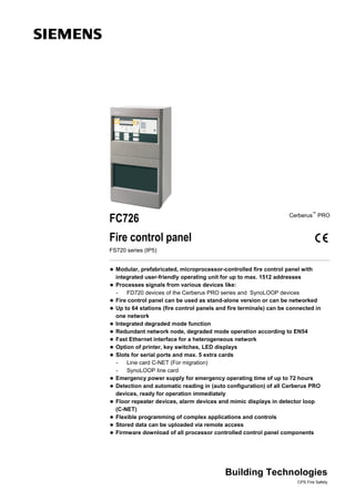
- 1. FC726 Cerberus™ PRO Fire control panel FS720 series (IP5) Modular, prefabricated, microprocessor-controlled fire control panel with integrated user-friendly operating unit for up to max. 1512 addresses Processes signals from various devices like: - FD720 devices of the Cerberus PRO series and SynoLOOP devices Fire control panel can be used as stand-alone version or can be networked Up to 64 stations (fire control panels and fire terminals) can be connected in one network Integrated degraded mode function Redundant network node, degraded mode operation according to EN54 Fast Ethernet interface for a heterogeneous network Option of printer, key switches, LED displays Slots for serial ports and max. 5 extra cards - Line card C-NET (For migration) - SynoLOOP line card Emergency power supply for emergency operating time of up to 72 hours Detection and automatic reading in (auto configuration) of all Cerberus PRO devices, ready for operation immediately Floor repeater devices, alarm devices and mimic displays in detector loop (C-NET) Flexible programming of complex applications and controls Stored data can be uploaded via remote access Firmware download of all processor controlled control panel components Building Technologies CPS Fire Safety
- 2. System overview Fire control panel FC10 or XC10 Fire detection or Extinguishing control unit collective 4 (8) loops max. 504 adresses 4 inputs 4 outputs FT2010/FT2011 Floor repeater terminal / Floor repeater display 24VDC ext. possible 1 input 2 inputs/outputs optionally Explosion- hazard area Remote access Engineering Tool, Operating Tool stub line Transmission of an alarm signal Transmission of a fault signal via FCI2007-A1 Fire controls via FCI2008-A1 Detection line collective Siemens, Synova SynoLINE300 or SynoLINE600 TM Conventional horn lines via FCI2009-A1 C-NET FDCI222 FDCL221 FDCIO222 FDM22x FDM221 DBS720 OH720 HI722 HI720 OP720 4 inputs FDCIO221 1 output FDCI221 OH720 24VDC ext. FDCIO223 FDCL221-Ex OOH740-A9-Ex FDM233-Ex FC723 Repeater FN2002 Cluster (C-WEB/SAFEDLINK) FC726 FT724 Mimic display FT2001-A1 DBS721 / DBS729 OP720 SynoLOOP FDOOT271 FDM273 FDCW241 FDA221/ FDA241 FDCI723 1 input Radio detectors Possible extensions for card cage FCL2001-A1 (C-NET) FCI2007-A1 (RT) • 4 integrated loops with max. 252 addresses per line card • Alarm, fault, local alarm FCL7201-Z3 (SynoLOOP) FCI2009-A1 (horn/monitored) • 4 loops, per loop 128 addresses • 8 monitored horn lines or monitored outputs FCI2008-A1 (programmed) • 12 freely programmable inputs/outputs per I/O card Mixed usage possible, but with a max. of 5 cards per control panel. 2 Building Technologies CPS Fire Safety
- 3. Networking topologies Up to 32 fire control panels und fire control terminals can be connected in a single clus- ter (C-WEB/SAFEDLINK) or up to 16 stations when the cluster is connected to a dan- ger management system. Using a fiber-optic Backbone (C-WEB/LAN) up to 14 of the above mentioned clusters (with up to 16 stations each) can be networked. The entire network may contain up to 64 stations. For details about system networking, please refer to product data sheet A6V10227649. 3 Building Technologies CPS Fire Safety
- 4. Characteristics – The FC726 is a modular fire control panel with integrated operating unit which processes signals from Cerberus PRO FD720 and SynoLOOP devices. – An integrated card cage with 5 slots allows – C-NET line cards FCL2001-A1 to be used (for extra lines) – SynoLOOP line cards, FCL 7201-Z3 – I/O card FCI2008-A1 (with 12 programmable inputs/outputs) – Mixed use of all line and I/O cards possible. – In the event of a defect, the extra line cards can be replaced without the control panel having to be powered down. – The fire control panel may be used as a stand-alone unit or networked. – The control panel can be programmed into a system with high levels of flexibility us- ing a user-friendly configuration tool (software). – Adaptation of customer texts on the terminal itself or using the configuration tool. – Up to 2000 events can be called up for each station according to various criteria. – Automatic summer/winter time changeover. – Integration to Siemens Danger Management System Functional elements Operating unit The following are located on the operating unit: – CPU module and electronic components for operating unit – Ethernet connection – Plug-ins for RS232, RS485 modules and networking modules (SAFEDLINK) – Space for 'Kaba' or 'Nordic' key switch – Space for event printer Periphery board The following are located on the peripheral board: – Connection terminals for C-NET loops, remote transmission (alarm, fault), horn outputs, programmable control inputs/outputs, monitored alarm and fault output, degrade supply, power supply – 2 plug-ins for loop extension (C-NET) Card cage (5 slots) There is a card cage on the rear housing panel for use of max. 5 line cards - C-NET line cards, - SynoLOOP line cards and/or I/O-cards. Power supply unit 150 W, emergency power supply The power supply supplies the hardware and charges the batteries – The batteries supply the emergency power in case of power failure Housing A pivoting mounting panel can be installed on the housing backplane to allow installa- tion of: – 1 fire brigade periphery module – 2 sounder modules (can also be mounted onto the U-rail TS35) Configuration The FXS7212 Cerberus engineering tool permits the system to be adapted to specific customers' requirements. 4 Building Technologies CPS Fire Safety
- 5. Application ranges The FC726 is ideally suited for medium-sized applications, e.g. hotels, high schools, office complexes, etc. or when networked as part of much larger applications. The FC726 can be used by the flexible cross-linking possibilities however also for ex- tensive systems. Operation Each control panel has an integrated operating panel. Additionally the control unit can be operation for another separate FT724 operator terminal. For details and further information, please refer to product data sheet A6V10207898. Overview of FC726 fire control panel Control panel Housing extensions FC726 ZA FH7204-Z3 FH7205-Z3 Housing (Large) Housing (Large extension) Housing (Large) 430 x 398 x 260 mm 430 x 796 x 260 mm Space for larger batteries 2 x FA2007-A1 (45 Ah) or 2 x FA2008-A1 (65 Ah) or 2 x FA2009-A1 (100 Ah) 4 loops with power supply (150 W) Space for larger batteries Max. battery capacity 45 Ah 4 x FA2006-A1 (26 Ah) or with card cage (5 slots) 4 x FA2007-A1 (45 Ah) or for extra line cards (C-NET) 2 x FA2008-A1 (65 Ah) or or I/O card 2 x FA2009-A1 (100 Ah) Printer External printer Operating add-ons FTO2001-A1 DL3750+ FCM7213-Y3 FCM7214-Y3 Event printer Matrix printer (external) 48 display groups 96 display groups can be fitted RS232 interface with one red/green + yellow LED with one red/green + yellow LED RS232 module must be RS232 module must be for retrofitting for retrofitting ordered separately ordered separately 5 Building Technologies CPS Fire Safety
- 6. FC726 configuration 9 11 25 59 310 17 15 16 17 23 12 1 27 242 4 7 20 24 19 6 26 18 22 8 21 13 14 Basic equipment Designation Notes 1 Rear (Large) FHA2005-A1 Items 1-6 –> basic equipment2 Periphery board (4 loops) FCI2004-A1 3 Power supply (SV 24V-150 W) V24230-Z6-A5 4 Mains terminals on TS35 DIN rail – Space for socket, relay modules etc. 5 Operating unit FCM72xx-xx System operation and CPU at the same time, incl. cover cap 6 Card cage (5 slots) FCA2008-A1 For C-NET and I/O cards 7 Space for batteries – 2 x 12 V / 17… 45 Ah Expansion 8 Relay module Z3B171 Relay for fire controls 9 Event printer FTO2001-A1 For event logging 10 Key switch (Kaba) FTO2005-C1 For operating access rights Key switch (Nordic) FTO2006-B1 11 Mounting plate FHA2007-A1 E. g. for fire brigade periphery module 12 Loop extension (FDnet/C-NET) FCI2003-A1 For loop extension of 2 to 4, number of addresses remains the same 13 Line card (C-NET) FCL2001-A1 For extra C-NET lines, 4 lines total, 252 addresses per line card 14 Line card (SynoLOOP) FCL7201-Z3 For extra SynoLOOP lines, 4 loops, max. 128 addresses per loop 15 RS485 module (isolated) FCA2002-A1 For peripheral devices with RS485 port 16 RS232 module (isolated) FCA2001-A1 For participant with RS232 port 6 Building Technologies CPS Fire Safety
- 7. 17 Network module (SAFEDLINK) FN2001-A1 For networking various stations 18 Repeater (SAFEDLINK) FN2002-A1 For the extension of the system bus C-WEB, max. 1 between 2 sta- tions (mounting direct onto plane surface, onto a U-rail TS35 or in housings FDCH221) 19 Sounder module FCA2005-A1 For split-up of 1 to 4 conventional horn lines 20 Battery (12 V, 17 Ah, VDS) FA2005-A1 For emergency power supplyBattery (12 V, 26 Ah, VDS) FA2006-A1 Battery (12 V, 45 Ah, VDS) FA2007-A1 21 Fire brigade periphery module FCI2001-D1 For Germany (FBF, FSD, ÜE, FSE, ÖA, KL) 22 19" mounting kit FHA2016-A1 For the installation in 3rd party housings 23 License key Sx FCA20xx For special functions 24 Cable kit (communication) FCA2014-A1 For flexible cable connections to the modules on the operating unit 25 Power supply kit (150 W, B) FP2005-A1 For additional power supply 26 I/O card FCI2008-A1 12 programmable inputs/outputs 27 Relay module Z3B171 Space for U-rail TS35 L=70 mm (on site) for max. 4 relay modules Technical data Mains voltage AC 98…127 V / AC 196…253 V Power supply 150 W Operating voltage DC 21…28.6 V Operating current max. 5 A Battery capacity 2 x 12 V, 45 Ah Battery monitoring / mains monitoring yes / yes Connectable detector series Cerberus PRO FD720 (C-NET) Number of C-NET addresses max. 1512 Number of lines Loops with loop extension – stub lines 4 / 8 8 / 16 C-NET (4 per line card) max. 20 Integrated inputs/outputs – Relay output – Remote transmission alarm / fault – Monitored outputs – Alarm / Fault / Horn – Free programmable inputs/outputs 1 / 1 1 / 1 / 2 12 Free programmable inputs/outputs with max. 5 extra I/O cards 60 (12 per card) Operating unit integrated Plug-in position for RS232, RS485 serial ports 2 Plug-in position for network modules 2 Plug-in position for loop extension 2 Slots for line cards (on fitted card cage) max. 5 Mounting spaces for cable kit (communication) 2 Sounder module max. 2 Ethernet connection RJ45 1 Operating temperature -8…+42 °C Storage temperature -20…+ 60 °C Humidity (no condensation permitted) ≤95 % rel. Dimensions (W x H x D) – Without cover cap – With Cover cap 430 x 796 x 260 mm 430 x 796 x 288 mm Color – Housing – Cover cap grey, ~RAL 7035 grey, ~RAL 000 50 00 Protection category (IEC 60529) IP30 Standards EN 54-2, EN 54-4 Approvals – VdS – LPCB – FM G210084 126bn/08 approved 7 Building Technologies CPS Fire Safety
- 8. Details for ordering Type Art. no. Designation Weight FC726-ZA S54400-C87-A1 Fire control panel 20.800 kg Extensions Z3B171 BPZ:4843830001 Relay module 250 V AC / 10 A (1 relay) 0.042 kg FTO2001-A1 A5Q00010126 Event printer 0.250 kg – A5Q00017619 Replacement printer rolls (10 rolls) 0.090 kg FTO2005-C1 A5Q00010113 Key switch (Kaba) 0.013 kg FTO2006-B1 A5Q00010129 Key switch (Nordic) 0.050 kg FHA2007-A1 A5Q00010151 Mounting plate 0.800 kg FCI2003-A1 A5Q00010136 Loop extension (C-NET) 0.064 kg FCL2001-A1 A5Q00009875 Line card (C-NET) 0.120 kg FCI2008-A1 S54400-A6-A1 I/O card (programmable) 0.120 kg FCL7201-Z3 S54400-A116-A1 Line card (SynoLOOP) 0.120 kg FCA2002-A1 A5Q00009923 RS485 module (isolated) 0.067 kg FCA2001-A1 A5Q00005327 RS232 module (isolated) 0.068 kg FN2001-A1 A5Q00012851 Network module (SAFEDLINK) 0.077 kg FN2002-A1 S24236-B2502-A1 Repeater (SAFEDLINK) 0.154 kg FCA2005-A1 A5Q00014866 Sounder module 0.140 kg FCA2014-A1 A5Q00023027 Cable kit (communication) 0.224 kg FCI2001-D1 A5Q00013100 Fire brigade periphery module 0.482 kg FH7204-Z3 S54400-B89-A1 Housing (Large extension) 11.800 kg FH7205-Z3 S54400-B86-A1 Housing (Large) 15.400 kg FHA2016-A1 A5Q00020179 19" mounting kit 3.000 kg FCM7213-Y3 S54400-B149-A1 Operating add-on (2xLED-ind.) 2.600 kg FCM7214-Y3 S54400-B150-A1 Operating add-on (4xLED-ind.) 2.800 kg FN2006-A1 S54400-A109-A1 Fiber network module (SM) 0.770 kg FN2007-A1 S54400-A110-A1 Fiber network module (MM) 0.770 kg Auxiliary power supply FP2003-A1 A5Q00016005 Power supply kit (70 W) 0.650 kg FP2004-A1 A5Q00020825 Power supply kit (150 W, A) for installation into empty housing 1.366 kg FP2005-A1 A5Q00018779 Power supply kit (150 W, B) for cascading 1.100 kg Networks (backbone) FN2008-A1 S54400-F94-A1 Ethernet-Switch 0.800 kg NK8237.2 S54461-C7-A1 Modbus GW 0.603 kg FHA2029-A1 S54400-B79-A1 Mounting kit for Ethernet switch (Comfort) 0.500 kg FHA2030-A1 S54400-B81-A1 Mounting kit for Ethernet switch (Large Ext.) 0.500 kg Batteries FA2005-A1 A5Q00019677 Battery (12 V, 17 Ah, VDS) 5.640 kg FA2006-A1 A5Q00019356 Battery (12 V, 26 Ah, VDS) 7.572 kg FA2007-A1 A5Q00022897 Battery (12 V, 45 Ah, VDS) 15.320 kg FA2008-A1 A5Q00019357 Battery (12 V, 65 Ah, VDS) 22.000 kg FA2009-A1 A5Q00023101 Battery (12 V, 100 Ah, VDS) 32.360 kg License keys FCA2033-A1 S54400-P154-A1 License key (S1) 0.010 kg FCA2034-A1 S54400-P155-A1 License key (S2) 0.010 kg FCA2035-A1 S54400-P156-A1 License key (S3) 0.010 kg External printer DL3750+ A5Q00023962 Matrix printer (external) 7.300 kg Spare part – A5Q00023963 Black typewriter ribbon for printer DL3750+ 0.078 kg Siemens Switzerland Ltd Infrastructure & Cities Sector Building Technologies Division International Headquarters CPS Fire Safety Gubelstrasse 22 CH-6301 Zug Tel. +41 41 724 24 24 www.siemens.com/buildingtechnologies © 2014 Copyright by Siemens Switzerland Ltd Data and design subject to change without notice. Supply subject to availability. Document no.. A6V10263277_f_en_-- Manual FS720 Edition 06.2014 Section 1