Tech-Forward - Achieving Business Readiness For Copilot in Microsoft 365
Compression Tool: A Time-Compression Enabling Technology
1. Compression Tool
Introduction
G
lobal competition, product customisation, accelerated product
obsolescence and continued demands for cost savings are forcing
companies to look for new technologies to improve their business
processes and speed up the product development cycle. Rapid prototyping (RP)
has emerged as a key enabling technology, with its ability to shorten product
design and development time.
Rapid prototyping is a technology for quickly fabricating physical models,
functional prototypes and small batches of parts directly from computer-aided design
(CAD) data. This technology has also been referred to as layer manufacturing, solid
free-form fabrication, material addition manufacturing and three-dimensional printing.
Rapid prototyping is a means of compressing the time-to-market of products and, as
such, is a competitiveness enhancing technology.
This article focuses on RP technology for building physical models and discusses
the role of this technology in ‘time compression’ engineering (TCE). A brief description
of three existing RP processes with the highest commercial impact is provided.
Examples of RP applications in five different areas are then presented. Finally, future
developments to achieve long-term growth in this field and realise the full potential of
RP technology are outlined.
ingenia
43
DUC PHAM OBE FREng
AND STEFAN DIMOV
MANUFACTURING ENGINEERING
CENTRE, CARDIFF UNIVERSITY
TECHNOLOGY AND INNOVATION
Rapid prototyping (RP) has
emerged as a key enabling
technology, with its ability to
shorten product design and
development time. This article
discusses the role of RP in ‘time
compression’ engineering and
provides a brief description of
three RP processes with the
highest commercial impact on the
market. The article also outlines
different applications and future
developments of this technology.
A time
compression
tool
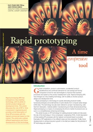
Imagesshowthefrozenstressdistributionforamodelofanaeroengineturbinerotor1
Rapid prototypingRapid prototyping
2. Rapid prototyping – an
enabling technology for
time compression
engineering
The main enabling technology behind
time compression engineering is 3-D
computer-aided design modelling. If
different design and manufacturing
activities are carried out concurrently it is
possible to compress the overall product
development time. This can also allow
engineers to be creative by providing
more time for design iterations (Figure 1).
Concurrent engineering environments
have evolved considerably during the
last few years to integrate 3-D modelling
with computer-aided manufacturing
(CAM), computer-aided engineering
(CAE), rapid prototyping and
manufacturing, and a number of other
applications. The 3-D model becomes a
central component of the whole product
or project information base, so that in all
design, analysis and manufacturing
activities the same data are utilised.
There is no duplication or possibility for
misunderstanding. Product information
captured in this way can be copied and
re-used; it is readily available for different
downstream applications.
Three-dimensional models and virtual
prototypes allow most problems with
fitting to become obvious early in the
product development process.
Assemblies can be verified for
interference. Structural and thermal
analysis can be performed on the same
models, employing CAE applications as
well as simulating downstream
manufacturing processes. Ultimately,
these very accurate and data-rich
models can be taken directly to RP and
CAM applications, speeding up process
planning and in some cases eliminating
the need for drawings.
Currently, there are a number of RP
machines available on the market but
only three technologies have a
significant commercial impact. These
RP processes are described below.2
● Stereolithography (SL): This
process relies on a photosensitive
liquid resin which forms a solid
polymer when exposed to ultraviolet
(UV) light (Figure 2). Stereolithographic
systems consist of a build platform
(substrate) which is mounted in a vat
of resin and a UV helium–cadmium
or argon ion laser. The first layer of
the part is imaged on the resin
surface by the laser using information
obtained from the 3-D solid CAD
model. Once the contour of the layer
has been scanned and the interior
hatched, the platform is lowered and
a new layer of resin is applied. The
next layer may then be scanned.
Once the part is completed, it is
removed from the vat and the excess
resin drained. The ‘green’ part is then
placed in a UV oven to be postcured.
● Selective laser sintering (SLS):
SLS uses a fine powder which is
heated with a carbon dioxide laser so
that the surface tension of the
particles is overcome and they fuse
together. Before the powder is
sintered, the entire bed is heated to
just below the melting point of the
material in order to minimise thermal
distortion and facilitate fusion to the
previous layer. The laser is modulated
such that only those grains that are in
direct contact with the beam are
affected. A layer is drawn on the
powder bed using the laser to sinter
the material. The bed is then lowered
and the powder-feed cartridge raised
so that a covering of powder can be
spread evenly over the build area by
ingenia
44
TECHNOLOGY AND INNOVATION
modellingmodelling
Conceptual design
Detail design
Prototyping
Tooling
Production Time
Conceptual
design
Detail
design
Engineering
analysis
Prototyping Tooling Production
3D CAD3D CAD
Rapid prototyping
and manufacturing
Serial
Concurrent
Engineering analysis
Virtual prototyping VR & FEAVR & FEA
Time
savings
Figure 1 Time compression engineering
Figure 2 Stereolithography
3. a counter-rotating roller. The sintered
material forms the part whilst the
unsintered powder remains in place
to support the structure and may be
cleaned away and recycled once the
build is complete (Figure 3).
There is another process, laser
sintering technology (LST), that
employs the same physical
principles. Figure 4 shows an LST
system equipped with two laser
beams working in parallel. Currently
such dual-laser systems are
available for processing
thermoplastics and sand.
● Fused deposition modelling
(FDM): FDM systems consist of two
movable heads (one for building the
part and one for the supports) which
deposit threads of molten material
onto a substrate (Figure 5). The
ingenia
45
TECHNOLOGY AND INNOVATION
Figure 3 Selective laser sintering
Figure 4 A dual-laser LST system (courtesy of EOS GmbH)
4. satisfy the specific requirements of a
growing number of new applications,
various software tools, build techniques
and materials have been developed.
Five examples in different application
areas are described in this section.2
● Functional models: Selective laser
sintering, one of the three rapid
prototyping processes detailed
above, is widely used for producing
polyamide-based models for
functional tests. The SLS production
of polyamide parts is generally cost-
effective when a small number of
parts (one to five) is required. The
housing in Figure 6 is a test part built
in glass-filled polyamide (a blend of
50% by weight polyamide powder
with a mean particle size of 50 µm
and 50% by weight spherical glass
beads with an average diameter of
35 µm) because it has to withstand
harsh test conditions, including
temperatures of about 100°C. As a
base part for mounting precision
components, it has to keep its
dimensions within close limits. To
produce this functional component
to the specified requirements, the
thickness of its walls was reduced to
2 mm and made uniform.
Furthermore, 2 mm non-functional
ribs were added across the housing
to stiffen it. The errors in 90% of all
functional dimensions of the built
component were between + 0.35
and – 0.31 mm.
ingenia
46
TECHNOLOGY AND INNOVATION
Figure 5 The fused deposition modelling process
Figure 6 Composite nylon housing:
without ribs (left), with ribs
(right)
Figure 7 Heat exchanger for a Pratt & Whitney PW6000 engine
material is heated to just above its
melting point so that it solidifies
immediately after extrusion and cold
welds to the previous layers.
Applications of rapid
prototyping technology
Rapid prototyping models are
becoming widely used in many
industrial sectors. Initially conceived for
design approval and part verification,
rapid prototyping now meets the needs
of a wide range of applications, from
building test prototypes with material
properties close to those of production
parts, to fabricating models for art and
medical or surgical uses. In order to
5. ● Patterns for investment and
vacuum casting: Rapid prototyping
is widely used for building patterns
for investment and vacuum casting.
For example, models built using any
of the three technologies listed
above can be employed as patterns
for both casting processes. The heat
exchanger assembly of a Pratt &
Whitney PW6000 engine shown in
Figure 7 was produced using SLS
patterns. The assembly includes
three cast aluminium components
that have to withstand high
temperature and pressure. These
complex castings are essentially
pressure vessels with multiple
portings, mountings and sensor
pads. The largest component
measures 600 mm in height and
325 mm in diameter (Figure 7). As a
relatively small number of
exchangers was required per year,
the SLS process was approved as a
production method for the
fabrication of the required casting
patterns. In general, RP patterns are
a cost-effective alternative when a
small number of parts, say up to 50,
of complex design is required and
the cost of a mould tool for wax
patterns is prohibitive.
● Medical or surgical models: Rapid
prototyping technologies are applied
in the medical/surgical area for
building models that provide visual
and tactile information. In particular,
RP models can be employed in the
following applications: operation
planning, surgery rehearsals, training
and prosthesis design. For instance,
two stereolithographic medical
models were built for a patient
suffering from a secondary
carcinoma of the right superior orbital
margin and the adjacent frontal bone.
The first model was used to plan the
resection of the cancerous bone and
also as an operation reference and
patient consent tool. The fabricated
plastic template was placed over the
model to check the match with the
surgeon’s resection line (Figure 8).
The second model was then
employed to construct an acrylic
custom implant (Figure 9). The
unaffected left superior orbital margin
was mirrored across to assist the
design of the implant. The operation
was reported as a complete success
and the surgeon was fully satisfied
with the quality and the cost of
utilising RP models.
● Art models: Another growing
application area for RP technologies
is art and design. Through building
RP models, artists can experiment
with complex artwork which supports
and enhances their creativity. Initially,
the high cost of RP models meant
strict limits on the size of the models.
However, recently, with the
introduction of relatively inexpensive
RP machines for quickly producing
design models, it has become cost-
effective to employ RP techniques in
many artistic applications. The
following example was part of work
conducted within the CALM (creating
art with layer manufacture) Project
supported by the Higher Education
Funding Council for England in an
initiative to promote the use of IT
within the academic art and design
community. The example is an
artwork representing a splash
spanning the inside of a plexiglass
vitrine (Figure 10). In its final
installation, the SLS model (Figure 11)
is to be incorporated into a plexi-box
exactly the width of the splash itself.
● Engineering analysis models:
Various software tools exist, mainly
based on finite elements analysis
(FEA), to speed up the development
of new products by enabling design
optimisation before physical
prototypes are available. However, the
creation of accurate FEA models for
complex engineering objects
sometimes requires significant
amounts of time and effort. By
employing RP techniques it is possible
to begin test programmes on physical
models much earlier and complement
the FEA data. RP models could be
used for visualisation of flow patterns,
thermoelastic tension analysis,
photoelastic stress analysis and
fabrication of models for wind tunnel
ingenia
47
TECHNOLOGY AND INNOVATION
Figure 8 The SLA model with the
resection template3
Figure 9 The SLA model together with
the template and the implant3
Figure 10 Cross-sections of the 3-D model of a water splash4
6. tests. The opening image shows an
example of an RP part produced for
photoelastic stress analysis. The part
was fabricated by stereolithography
because the SL resin material exhibits
birefringence when under stress and
irradiated with polarised light. The
fringe patterns seen in this image,
which indicate the stresses and
strains in the part, were ‘frozen’ by
warming the loaded SL model to a
level above the resin–glass transition
temperature and then gradually
cooling it back to room temperature.
Future developments
The field of rapid prototyping is just over
ten years old. In spite of this, significant
progress has been made in widening
the use of this technology and in the
development of new processes and
materials. To achieve long-term growth
in this field and realise its full potential, a
number of challenges remain. These
challenges could be grouped under the
following categories5
:
● Productivity/cost of RP machines:
To benefit truly from the ‘direct’
fabrication capabilities of RP
processes, especially when the serial
production of parts is planned, their
productivity should be increased and
machine costs reduced significantly. It
is expected that long-term growth in
the RP industry will come from
applications that are impossible or
very difficult, costly and time-
consuming to implement with
conventional manufacturing
techniques. Therefore, new RP
machines should address the specific
requirements of these applications.
Furthermore, it is expected that wider
use of RP machines for rapid
manufacturing will lead to reduction of
the cost of RP machines.
● Materials: One of the main
limitations of RP processes is the
limited variety of materials and their
properties, and also their relatively
high cost. Significant research efforts
are focused on the development of a
broader range of materials that
simulate very closely the properties of
the most commonly used engineering
plastics. Recently, the fabrication of
multi-materials and heterogeneous
objects has attracted the attention of
the research community.
Developments in this area will make
possible the fabrication of objects
with multiple and conflicting functional
requirements.
● Process planning: With the
increase of part complexity and the
range of available RP materials and
RP machines, there is a need for
more advanced process planning
tools, in particular tools that could
relate process variables to part
quality characteristics and address
the process-specific requirements
associated with the fabrication of
parts from heterogeneous materials.
● Rapid prototyping data formats
and design tools:
The stereolithography format, a de
facto standard for interfacing CAD
and RP systems, has a number of
drawbacks inherent in the
representation scheme employed.
Work on the development of new
formats continues in order to address
the growing need of RP applications
for more precise methods of data
representation. Also in recent years,
with the emergence of RP processes
for fabrication of heterogeneous
objects, there is increasing interest in
developing new CAD tools that
enable the design of objects with
varying material composition and/or
microstructure. ■
Bibliography
1 Anon. (1994) 3D Systems Newsletter:
The Edge, 3D Systems, 26081
Avenue Hall, Valencia, California, USA.
2 Pham, D.T. and Dimov, S.S. (2001)
Rapid Manufacturing: The
Technologies and Applications of
Rapid Prototyping and Rapid
Tooling, Springer Verlag, London.
3 D’Urso, P.S. and Redmond, M.J.
(2000) ‘Method for the resection of
cranial tumours and skull
reconstruction’, British Journal of
Neurosurgery, 4(6): 555–59.
4 Anon. (1998) CALM Project Final
Report, University of Central
Lancashire, Preston. http://www.uclan.
ac.uk/clt/calm/overview.htm
5 Pham, D.T. and Dimov, S.S. (2003)
‘Rapid prototyping and rapid tooling
– the key enablers for rapid
manufacturing’, Proceedings of the
Institution of Mechanical Engineers,
Part C, 217, pp 1–23.
Acknowledgements
The authors wish to thank the Institution
of Mechanical Engineers to re-use
material from Reference 5 in this article.
Stefan Dimov is Distinguished Senior
Research Fellow and
Operations Director of
the Manufacturing
Engineering Centre at
Cardiff University. He is
the recipient of the
2000 and 2002 Thomas
Stephen Group Prizes from the
Institution of Mechanical Engineers.
Duc-Truong Pham is Professor of
Computer-Controlled Manufacture
and Director of the
Manufacturing
Engineering Centre at
Cardiff University. The
MEC has won the
Queen’s Anniversary
Prize and the Secretary
of State for Trade and Industry’s First
Prize for its research and
programme of practical technology
transfer and partnership building.
ingenia
48
TECHNOLOGY AND INNOVATION
Figure 11 SLS model representing a
water splash5