1. THERMO JET PRINTER
A.W.Bell's 3 Thermojet object printers use a jetting process that builds up a
wax-like polymer layer by layer
The first layer is sprayed directly onto a platen by a row of presicely controlled jets that can produce points
0.08mm square. This layer is then machined by a hot roller to a thickness of 0.08mm. The platen then drops
and a new layer is jetted over the first. This process is repeated thousands of times to build a part. Print time
is determined by model height. A model 254 x 192 x 200mm can be built in under 30hrs.
Parts with undercuts, overhangs and other complex features are no problem due to the automatic support
structure demonstrated in the next animation.
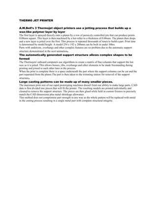
The automatically generated support structure allows complex shapes to be
formed
The Thermojets' onboard computers use algorithms to create a matrix of fine columns that support the hot
wax as it is jetted. This allows bosses, ribs, overhangs and other elements to be made freestanding during
printing and joined to each other later in the process.
When the print is complete there is a space underneath the part where the support columns can be cut and the
part separated from the platen.The part is then taken to the trimming station for removal of the support
structure.
Large casting patterns can be made up of many smaller pieces.
The maximum print size of our rapid prototyping machines doesn't limit our ability to make large parts. CAD
data is first divided into pieces that will fit the printer. The resulting models are printed individually and
cleaned to remove the support structure. The pieces are then glued while held in custom fixtures to precisely
match the CAD dimensions plus metal shrinkage allowance.
This method does not compromise part strength in any way as the whole pattern will be replaced with metal
in the casting process resulting in a single metal part with complete structural integrity.