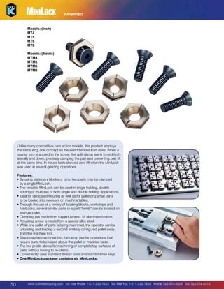
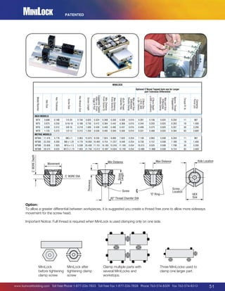
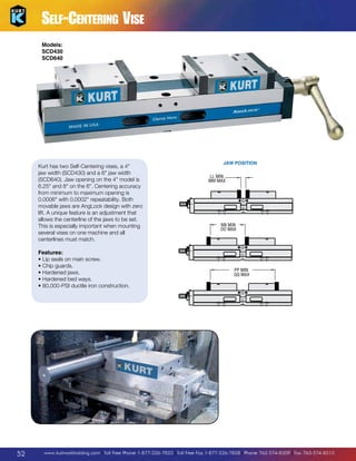
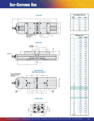
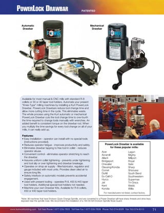
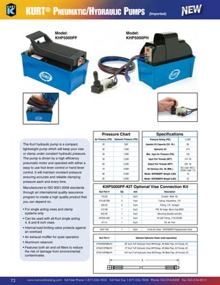
Downloaded 11 times


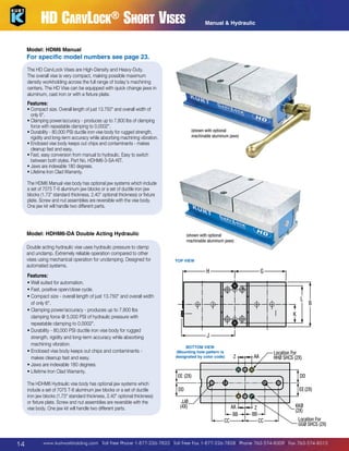


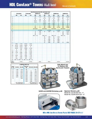


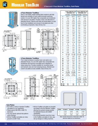
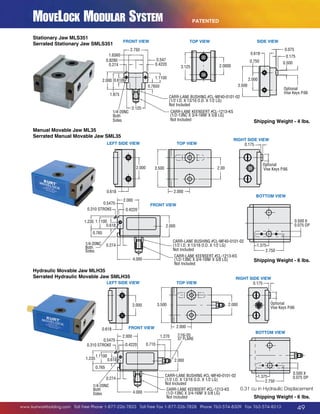
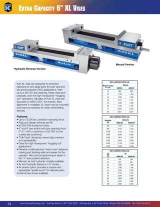
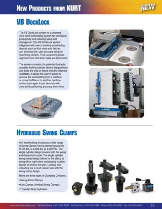
![HD CarvLock® Towers
CTHDHL64 Hydraulic Tower – English
CTHDHLM64 Hydraulic Tower – Metric
This hydraulically operated eight station tower
features all-new design for fast loading of parts.
All internalized hydraulic piston/nut saves
valuable space. Includes all original KURT
AngLock precision clamping and iron clad rigid
construction for damping vibration.
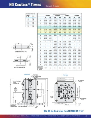
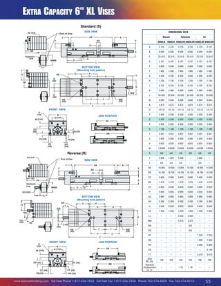
Features:
• ydraulically operated eight station
H
CTHDHLM64 Cluster Tower.
• tilizes an all internal hydraulic piston nut to
U
12.500 (SQUARE)
conserve space. Pressure is maintained until
6.250
1.97 X 45° (4X)
released by operator or triggering device.
Easy disconnect for pallet shuttle.
R
• epeatable clamping to 0.0002. Each station
DR C'BORED
delivers up to 7,100 lbs. of clamping force at FOR 5/8 SHCS
(4X)
4,500 PSI.
6.299
[160mm] face is controlled separately for
•
Each
convenient part loading and removal.
J
12.598• aw opening is 4 per station.
[320mm] ach face has a maximum total stroke of 1/4
•E
(SQUARE)
.984 [25mm]
(1/8 per station).
DR
J
• aw options available: Hard jaws, machinable C'BORED
FOR
aluminum. machinable ductile iron. See pg.27 1/2 SHCS
(4X)
B
• ase sizes available: 400mm, 500mm, 630mm.
• ifetime Iron Clad Warranty
L
(shown with optional hard jaws)
7.874 [200mm]
15.748 [400mm] (SQUARE)
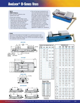
SIDE VIEW
TOP VIEW
12.500 (SQUARE)
6.250
1.75
24.61
1.97 X 45° (4X)
DR C'BORED
FOR 5/8 SHCS
(4X)
6.299
[160mm]
20.85
12.598
[320mm]
(SQUARE)
.984 [25mm]
DR C'BORED
FOR 1/2 SHCS
(4X)
9.492
7.874 [200mm]
15.748 [400mm] (SQUARE)
18mm 55mm (2X)
(5X)
75mm (2X)
M16 x 2
(5X)
1.250
HD HDL J aw K its F ixture P lates SEE PAGES 24-27
www.kurtworkholding.com | Toll Free Phone 1-877-226-7823 | Toll Free Fax 1-877-226-7828 | Phone 763-574-8309 | Fax 763-574-8313
+
21](https://image.slidesharecdn.com/kurtcatalog2014-140115101915-phpapp02/85/Kurt-Catalog-2014-21-320.jpg)


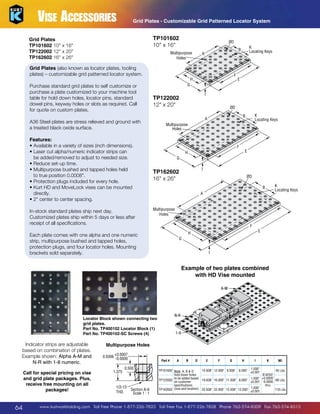
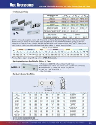


The document provides information about Kurt workholding products including: - The new SideWinder vise that mounts vertically to the back of 6" Kurt vises for secondary operations. - The new PinLock mounting system for quickly and accurately positioning fixture plates with locators and receiver bushings. - Specifications and details for the PinLock locators and receiver bushings. - An application chart showing Kurt workholding solutions for different machine types and operations.