
Recommended
More Related Content
What's hot
What's hot (18)
Similar to Use mic to increase ammonia production
Similar to Use mic to increase ammonia production (20)
Recently uploaded
Recently uploaded (20)
Use mic to increase ammonia production
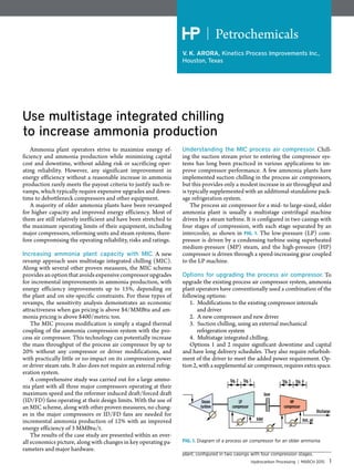
- 1. Hydrocarbon Processing | MARCH 2015 1 Petrochemicals V. K. ARORA, Kinetics Process Improvements Inc., Houston, Texas Use multistage integrated chilling to increase ammonia production Ammonia plant operators strive to maximize energy ef- ficiency and ammonia production while minimizing capital cost and downtime, without adding risk or sacrificing oper- ating reliability. However, any significant improvement in energy efficiency without a reasonable increase in ammonia production rarely meets the payout criteria to justify such re- vamps, which typically require expensive upgrades and down- time to debottleneck compressors and other equipment. A majority of older ammonia plants have been revamped for higher capacity and improved energy efficiency. Most of them are still relatively inefficient and have been stretched to the maximum operating limits of their equipment, including major compressors, reforming units and steam systems, there- fore compromising the operating reliability, risks and ratings. Increasing ammonia plant capacity with MIC. A new revamp approach uses multistage integrated chilling (MIC). Along with several other proven measures, the MIC scheme provides an option that avoids expensive compressor upgrades for incremental improvements in ammonia production, with energy efficiency improvements up to 15%, depending on the plant and on site-specific constraints. For these types of revamps, the sensitivity analysis demonstrates an economic attractiveness when gas pricing is above $4/MMBtu and am- monia pricing is above $400/metric ton. The MIC process modification is simply a staged thermal coupling of the ammonia compression system with the pro- cess air compressor. This technology can potentially increase the mass throughput of the process air compressor by up to 20% without any compressor or driver modifications, and with practically little or no impact on its compression power or driver steam rate. It also does not require an external refrig- eration system. A comprehensive study was carried out for a large ammo- nia plant with all three major compressors operating at their maximum speed and the reformer induced draft/forced draft (ID/FD) fans operating at their design limits. With the use of an MIC scheme, along with other proven measures, no chang- es in the major compressors or ID/FD fans are needed for incremental ammonia production of 12% with an improved energy efficiency of 3 MMBtu/t. The results of the case study are presented within an over- all economics picture, along with changes in key operating pa- rameters and major hardware. Understanding the MIC process air compressor. Chill- ing the suction stream prior to entering the compressor sys- tems has long been practiced in various applications to im- prove compressor performance. A few ammonia plants have implemented suction chilling in the process air compressors, but this provides only a modest increase in air throughput and is typically supplemented with an additional-standalone pack- age refrigeration system. The process air compressor for a mid- to large-sized, older ammonia plant is usually a multistage centrifugal machine driven by a steam turbine. It is configured in two casings with four stages of compression, with each stage separated by an intercooler, as shown in FIG. 1. The low-pressure (LP) com- pressor is driven by a condensing turbine using superheated medium-pressure (MP) steam, and the high-pressure (HP) compressor is driven through a speed-increasing gear coupled to the LP machine. Options for upgrading the process air compressor. To upgrade the existing process air compressor system, ammonia plant operators have conventionally used a combination of the following options: 1. Modifications to the existing compressor internals and driver 2. A new compressor and new driver 3. Suction chilling, using an external mechanical refrigeration system 4. Multistage integrated chilling. Options 1 and 2 require significant downtime and capital and have long delivery schedules. They also require refurbish- ment of the driver to meet the added power requirement. Op- tion 2, with a supplemental air compressor, requires extra space. Steam turbine Gear Inlet Inst. air Discharge Stg. 2 Stg. 1 Stg. 3 Stg. 4 LP compressor HP compressor FIG. 1. Diagram of a process air compressor for an older ammonia plant, configured in two casings with four compression stages.
- 2. 2 MARCH 2015 | HydrocarbonProcessing.com Petrochemicals In both of these options, the greater steam demand for the tur- bine drivers will require an additional surface condenser in the steam system to accommodate the extra steam condensing load, unless an electric option is viable. Both of these options have been implemented in a number of ammonia plants and are eco- nomically justified, with significant capacity additions that are typically in excess of 25%. Option 3, suction chilling, is widely practiced for gas tur- bines in the power industry, but it is not a very popular option in ammonia plants. A few ammonia plants have implemented this option, using an external refrigeration system that adds power and plot space requirements. This option is much less expensive than the first two options, but it provides only a modest increase in air capacity (approximately 5%) and is rarely economically justified.Thisisevidentfromthefactthatonlyahandfulofcom- panies have implemented suction chilling in ammonia plants. Option 4, a new approach using the MIC scheme, provides a cost-effective option to increase the air capacity by up to 20% without additional power or the use of an external refrigeration system. However, this option does require additional space. The MIC solution. ThetypicalMICschemeshowninFIG. 2 and FIG. 3 is a staged thermal coupling of the process air compressor withtheammoniacompressorsystemwithintheammoniaplant. A direct or indirect chilling scheme, or a combination of the two schemes, can be used, depending on the site constraints. The di- rect chilling scheme provides the advantage of being the most ef- ficient, with the lowest capital and plot space requirements. As a part of the ammonia plant revamp for higher capacity, the synthesis loop (synloop) is upgraded with an additional convert- er bed to suitably increase the single-pass ammonia conversion rate. Higher ammonia conversion results in a reduced gas circula- tion flowrate and lower refrigeration demand within the synloop. The freed-up ammonia streams, which are at different tem- perature levels from the existing ammonia compressor system, are suitably integrated in the staged chilling of the process air compressor, as well as in the makeup syngas compressor. The extent of thermal integration is suitably staged so as to minimize the ammonia compression power to well below its maximum design limits. Furthermore, the extent of the synloop upgrade is suitably synchronized with the upgrade of the front end of the ammonia plant to minimize the additional hardware, downtime and capital requirements. The higher mass flow of air available is then preheated to higher than the base temperature, using a combination of split flow and an external steam exchanger, as shown in FIG. 4. The use of a split flow scheme is plant- and site-specific, and it great- ly helps minimize the pressure drop and compression duty with an additional degree of air preheat to maximize the incremental ammonia production. Benefits of MIC scheme with other measures. The MIC modification, along with other measures, provides the poten- tial to achieve incremental increases in ammonia capacity and energy-efficiency improvements up to 15%, with the following key benefits: • No modifications are needed for any of the following major compressors, with only a small change in additional steam consumption: o Process air compressors o Syngas compressor o Ammonia compressor • No potential change in the pressure of the main surface condenser for steam turbines To stage 2 air compressor Condensate Intake air via filter Return headers Existing ammonia refrigeration system Liquid ammonia To MP surge drum To LP surge drum Stage 1 air compressor FIG. 2. Typical direct MIC scheme. To stage 2 air compressor Condensate Intake air via filter Return headers Existing ammonia refrigeration system Supply headers To MP surge drum Liquid NH3 To LP surge drum Stage 1 air compressorChilling water loop with pumps and buffer FIG. 3. Typical indirect MIC scheme. Air from process air compressor Primary effluent Secondary reformer Convection services Flue gas FIG. 4. Scheme showing a combination of split flow and an external steam exchanger.
- 3. Hydrocarbon Processing | MARCH 2015 3 Petrochemicals • Proportionately reduced steam demand at all levels improves energy efficiency • Reconfiguration and integration allows the temperature to be increased for the following streams, despite space constraints in the convection section: o Process air o Mixed feed o Superheated steam • Increases in the process air flow and temperature allow the outlet temperature of the secondary reforming unit to be raised, resulting in reduced methane slip and improved H2/N2 ratio for better synloop efficiency • The combination of a higher degree of preheat of mixed feed coupled with process air easily permits shifting the reforming load from the primary reformer to the secondary reformer • The steam-to-carbon (S:C) ratio in the primary reformer can also be decreased, despite a reduction in the overall methane slip, resulting in: o Reduced arch firing, which could be indirectly used to raise reformer tube outlet temperature for the same tube metal temperature o Reduced load on ID/FD fans, which could be further reduced by replacing a leak-prone rotary air preheater o Reduced mass flowrate of syngas to the cooling train, for improved hydraulics and pressure profile for higher capacity • Higher steam superheat temperature coupled with lower condensing pressure helps to reduce the steam rates for the same power demand. Key bottlenecks in old ammonia plants. A majority of the old ammonia plants are still relatively inefficient, and most of them are operated close to the design limits of the major equip- ment. Some of the key bottlenecks in the old ammonia plants are listed below: • Limits of ID/FD fans in the primary reformer: o Excessive air leakage from the old rotary-type air preheaters o Higher-than-design excess air for burners o Proportionately high firing load on arch burners due to limiting mixed feed preheat temperature, limiting air preheat temperature and higher-than-design S:C ratio • Higherinertsinmakeupgas (MUG): o Higher-than-expected methane slip in reforming due to lower temperature at the outlet of the secondary reformer, as a result of limited process air compressor capacity and limited preheat temperature of process air o Higher-than-expected CO2 slip due to: ❒ Limited solvent circulation rate ❒ Limited cooling of lean solvent due to limited cooling water (CW) or heat transfer surface ❒ Higher-than-expected loading of the lean solvent ❒ Non-optimal solvent concentration ❒ Mass transfer and hydraulic limitations of absorber and stripper internals • Major compressors: o Reached maximum volumetric limit at maximum design speed o Actual operational efficiency is lower than design o Higher-than-design suction temperature (percent of relative humidity for air compressors) o Limited intercooling o Unfavorable plant hydraulics (lower-than-design suction pressure) • Plant throughput limitations: o Higher-than-design S:C ratio o Higher-than-design level of inerts in MUG o Inefficient synloop and poor feed efficiency o Higher-than-expected system pressure drop • Excessive steam venting from the deaerator: o Excessive reboil load in CO2 strippers o Excessive temperature in the main surface condenser • Higher temperature in the main surface condenser of turbines: o Excessive backpressure due to higher-than-design load o Limiting heat transfer surface o Efficiency loss in condensing turbines due to lower steam superheat temperature and higher-than-expected steam rates. Case study. A case study of a large ammonia plant is outlined. The referenced ammonia plant had been stretched to its operat- ing limits, with the following constraints: • Process air compressor near its maximum design speed • ID/FD fans of the primary reformer at full open conditions • Syngas compressor near its maximum design speed • Ammonia compressor near its maximum design speed • No extra space in the convection section to add coils • High inerts in MUG due to high methane and CO2 slippage • Excess venting of steam from the deaerator • High energy consumption. This revamp study posed a major challenge to provide viable capacity and energy improvements without expensive compres- sor upgrades. Base speed: 103.6% Overall performance curve-base (process air compressor) ammonia capacity: 100% Overall performance curve-with MIC (process air compressor) ammonia capacity: 112% Volumetric flow, % Mass flow, % Volumetric flow, % Mass flow, % Speed with MIC: 101.4% 105%105% 100% Dischargepressure,% Dischargepressure,% 100% 100% 114% 108 100 FIG. 5. The mass flowrate of the process air compressor is increased, with reduced speed and without any increase in its power requirement.
- 4. 4 MARCH 2015 | HydrocarbonProcessing.com Petrochemicals List of major modifications. Based on a comprehensive study using the MIC scheme, no upgrades were required in any of the major compressors for a capacity increase of 12%, along with energy savings of 3 MMBtu/t. The following major changes were required as a part of the revamp: • MIC system • Replacement of rotary air preheater with plate-type preheater • Minor modifications of feed preheat coil • LP flash column system in CO2 removal • Additional single-bed converter • Few parallel exchangers for additional duty • Larger impellers for pumps. Key performance parameters for the base case and the MIC revamp are shown in TABLE 1. Process air compressor. Using the MIC scheme, including the two inter- mediate stages, the mass flowrate of the process air compressor is increased to 114% with reduced speed and without any increase in its power requirement, as indicated in FIG. 5. All of the chilling duty is internally supplied, without any need for an external refrigeration package. No modifications of the air compressor or its driver are required. Each stage of the air compressor is rated for its limitations and any cooling require- ment for the target capacity. The MIC scheme is suitably staged and optimized to minimize the compression requirements of both ammonia and air compressors, along with some additional modifications for size, space and capital requirements. The speed of the makeup syngas compressor is also reduced for the revamp case. It is accomplished by slightly raising its suction pressure and by lowering the suction temperature. With a balanced upgrade of the synloop and the front end, the speed of the ammonia compressor is marginally reduced. Reforming area. Reconfiguration and integration allow the temperature of the following streams in the reforming area to be increased, despite space constraints in the convection section: • Process air • Mixed feed • Superheated steam. Increases in the process air flow and temperature permit a rise in the outlet temperature of the secondary reforming, re- sulting in reduced methane slip and an improved H2/N2 ratio for better synloop efficiency. A combination of a higher degree of preheat of mixed feed coupled with higher temperature of the process air easily permits shifting of the reforming load from the primary reformer to the secondary reformer. In addition, the S:C ratio in the primary re- former is also reduced, despite a decrease in the overall methane slip that results in reduced arch firing, which could be indirectly used to raise the reformer tube outlet temperature without affect- ing the tube metal temperature. It also helps reduce the load on theID/FDfans,whichcouldbeevenfurtherimprovedbyreplac- ingtheleak-pronerotaryairpreheaterwithaplate-typepreheater. A reduced mass flowrate of syngas (due to a lower S:C ratio) to the cooling train also helps the hydraulics and the pressure profile for higher capacity. A higher steam superheat tempera- ture coupled with lower condensing pressure helps reduce the steam rates for the same power demand. CO2-removal area. The CO2-removal system scheme is a conventional, single-stage MDEA and piperazine. To overcome the mass-transfer and hydraulics limitations in the CO2-removal sections, several schemes were simulated 800 -8 -6 -4 -2 0 2 4 6 825 Superheat temperature, °F MP steam temperature vs. steam rate Steamratechange,% 850 900 FIG. 7. MP steam temperature vs. steam rate. TABLE 1. Key performance parameters Parameter Base case Revamp Ammonia capacity Base 112% Energy consumption, MMBtu/t Base –3 Mixed feed preheat temp., °F Base +40 S:C ratio, mol % 3.5 3.15 Process air preheat temp., °F Base 105 Steam superheat temp., °F Base +35 Secondary outlet temp., °F Base +50 MUG suction pressure, psi Base +15 Inerts in MUG, mol% Base 65% MUG H2/N2 ratio, mol% 3.06 3 Loop H2/N2 ratio, mol % 3.65 3 NH3 in converter effluent Base +5% mol Purge rate, mass rate Base 88% Ammonia concentration profile, two beds (base) Ammonia capacity: 100% Ammonia concentration profile, three beds (revamp) Ammonia capacity: 112% Temperature Temperature Dischargeconcentration,mol% 25 Dischargeconcentration,mol% 25 00 FIG. 6. The ammonia loop is upgraded with an additional single-bed converter.
- 5. Hydrocarbon Processing | MARCH 2015 5 Petrochemicals and further reviewed based on a cost-benefit analysis. Several changes were made in the revamp scheme: 1. Optimization of the MDEA and piperazine concentration in the solvent 2. Inclusion of an LP flash tower to offload the stripper reboiler duties by 16% 3. Replacement of existing packing with more efficient, lower-pressure drop packing 4. Replacement of the pump impellers, along with the supplemental exchanger area 5. Addition of the hydraulic turbine in the rich solvent stream. A two-stage scheme was also considered and simulated, but was discontinued based on the cost-benefit analysis. The cooler lean solvent, coupled with a slight increase in lean solvent flow, helped to significantly reduce the CO2 slip, thereby lowering the total inerts to the loop. Reducing the CO2 stripper duty by approximately 16% offloaded the stripper internals without any modification re- quired, and completely eliminated the large continuous steam vent from the deaerator, resulting in energy savings. Ammonia synloop. The ammonia loop is suitably upgraded with an additional single-bed converter, as shown in FIG. 6, with a relative ammonia concentration profile. The upgraded am- monia conversion is carefully chosen to balance the capacity increase in the front end for minimum modifications and capi- tal requirements. 800 -8 -6 -4 -2 0 2 4 6 825 Superheat temperature, °F HP steam temperature vs. steam rate Steamratechange,% 850 900 FIG. 8. HP steam temperature vs. steam rate. 3.5 4.5 5.5 6.5 7.5 8.5 9.5 -8 100 110 120 130 140 150 160 170 -6 -4 -2 0 2 4 6 8 Surface condenser pressure, in. Hg Surface condenser Condensing pressure vs. steam rate Steamratechange,% Surfacecondensingtemperature,°F FIG. 9. Condensing pressure vs. steam rate. Contact VK ARORA (01) 2817731629 vka@kpieng.com
- 6. 6 MARCH 2015 | HydrocarbonProcessing.com Petrochemicals With an increase of ammonia conversion in the synloop, the refrigeration duty requirement from the ammonia com- pressor is significantly reduced. The spare load from the am- monia compressor is used to provide the chilling duty of the process air compressor and the makeup syngas compressor without any modifications or power increases in the ammonia compressor. With a higher ammonia conversion, the outlet tempera- ture will increase beyond the design temperature of the exist- ing boiler feedwater (BFW) preheater. For this reason, a new exchanger is added before the existing BFW preheater. In ad- dition, a parallel CW exchanger is added for more ammonia condensation at the CW level. Steam system. The steam system is suitably optimized and balanced for higher ammonia capacity. It takes advantage of a higher degree of steam superheat at the HP and MP levels, and it also reduces the steam rates to minimize the surface con- denser pressure and load. Furthermore, by reducing the stripper reboil duty, the LP vent from the deaerator or excess LP steam can be significant- ly minimized, resulting in improved energy efficiency. For every 50°F temperature rise in the degree of superheat, the condensing steam turbine steam demand will decrease by about 3.5%, as shown in FIG. 7 and FIG. 8. Most of the surface condensers in ammonia plants are over- loaded with as high as 9 in. of mercury (Hg) pressure, as op- posed to a typical Hg pressure of 3.5 in. to 4.5 in. for normal operation. For a reduction of every 1 in. of Hg in backpressure in the main surface condenser, there is an approximate rise in condensing turbine efficiency of about 3%, as indicated in FIG. 9. Economics. The economics of the case study, in terms of internal rate of return (IRR) for ammonia pricing of $400/met- ric ton and $500/metric ton, are shown in FIG. 10 and FIG. 11. IRR estimation also considers varying gas prices of $4/MM- Btu to $10/MMBtu in step changes of $2/MMBtu, along with the capital sen- sitivity from –10% to +20%. This estima- tion provides a reasonable representation of various global locations for the assess- ment of the MIC scheme. The following assumptions are used in the economic evaluation: • CAPEX: total installed cost, including owner’s costs • Project completion: 36 months • Operating rate: 100% • Utility rates: typical of US Gulf Coast • Financing: internally funded (no debt) • Lifecycle: 15 years • Discount rate: 10% • Loan interest: 8% • Tax rate: 25% • New catalyst life: 15 years • Ammonia prices: $400/metric ton and $500/metric ton. As expected, the IRR greatly improves with higher ammo- nia and gas prices. Interestingly, the estimated IRR is higher than the typical minimum of 15%, even with the lowest gas price of $4/MMBtu and a 20% higher CAPEX than estimated. The IRR improves with higher ammonia and gas prices. Takeaway. The MIC scheme, in conjunction with other pro- cess improvement measures, provides a cost-effective option to ammonia plant operators for incremental improvements in capacity and energy efficiency up to 15%, while avoiding ex- pensive upgrades of major compressors. The sensitivity analysis demonstrates an economic attrac- tiveness for gas prices above $4/MMBtu and ammonia prices above $400/metric ton, mainly for revamps. The ammonia plant locations with higher feed gas prices will provide higher economic returns. The opportunity to use these incremental improvements in ammonia plants is most promising in situations where capital and/or additional feed gas availability is limited. 10 0 5 10 15 20 25 30 35 40 50 60 70 Base 10 Base investment, % $4/MMBtu gas $6/MMBtu gas $8/MMBtu gas $10/MMBtu gas IRR,% 15 20 FIG. 10. IRR for ammonia pricing of $400/metric ton. 10 0 5 10 15 20 25 30 35 40 50 60 70 Base 10 Base investment, % $4/MMBtu gas $6/MMBtu gas $8/MMBtu gas $10/MMBtu gas IRR,% 15 20 FIG. 11. IRR for ammonia pricing of $500/metric ton. V. K. ARORA is the director of process and strategic business development at Kinetics Process Improvements (KPI Inc.) in Houston. Prior to this role, he was responsible for the development and implementation of a large petrochemicals complex for a Saudi Arabia location to produce acrylic acid, oxo-alcohols, syngas and esters. He is presently involved in the development of a new ammonia project from offgases. He is a licensed professional engineer in Texas with a BTech degree in chemical engineering from IIT, in Delhi, India. Prior to joining KPI, he worked at CBI/Lummus in the US in various positions, including technology director and manager. He also worked at KBR, SABIC, B&V, Reliance, and Technip in various process functions, including design and startup.