
Recommended
More Related Content
More from kiakaha
More from kiakaha (20)
Recently uploaded
Recently uploaded (20)
Hvac Solution Supported Piping Systems
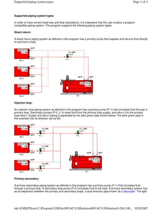
- 1. Supported piping system types Page 1 of 3 Supported piping system types In order to have correct head loss and flow calculations, it is imperative that the user employ a program compatible piping system. This program supports the following piping system types: Direct return: A direct return piping system as defined in this program has a primary pump that supplies and returns fluid directly to and from a load. Injection loop: An injection loop piping system as defined in this program has a primary pump (P-1) that circulates fluid through a primary loop. Secondary pumps (P-2, 3, 4) draw fluid from the primary loop supply, and return it to the primary loop return. Supply and return piping is separated by the dark green pipe shown below. The dark green pipe in this example has its direction set as left. Primary-secondary: A primary-secondary piping system as defined in this program has a primary pump (P-1) that circulates fluid through a primary loop. A secondary loop pump (P-2) circulates fluid to the load. A primary-secondary system has as its separation between the primary and secondary loops, a dual direction pipe known as a decoupler. The light mk:@MSITStore:C:Program%20FilesHVAC%20SolutionHVAC%20Solution%204.1H... 9/20/2007
- 2. Supported piping system types Page 2 of 3 green pipe in this example has its direction set as dual. Bypass: A bypass piping system as defined in this program has a primary pump (P-1) that circulates fluid through a primary loop. Secondary pumps (P-2, 3, 4) circulate fluid to each load. A bypass system has as its separation between the primary and secondary loops a pipe known as a bypass. The dark green pipe in this example has its direction set to down and the load entering temperature set lower than the generation system leaving temperature. This allows return fluid to mix with supply fluid to provide the lower load entering temperature. Sub-loop: A sub-loop piping system as defined in this program has a primary pump (P-1) that circulates fluid through a primary loop. Secondary pump (P-2) exists to mix temperatures down. Sub-loop pumps (P-3, 4, 5) provide flow to each load. In the example below the primary loop is separated from the secondary loop with a decoupler and the sub-loop is separated from the secondary loop by a bypass. mk:@MSITStore:C:Program%20FilesHVAC%20SolutionHVAC%20Solution%204.1H... 9/20/2007
- 3. Supported piping system types Page 3 of 3 Single pipe system: A single pipe system uses a common pipe for both supply and return. A primary pump (P-1) pumps fluid though the primary loop. Secondary pumps (P-2, 3, 4) draw off and return fluid to the single pipe primary loop. A cascading temperature effect is the result of this piping system. Each load uses a portion of the available fluid temperature differential until the return water temperature is reached by the final load. If a load's leaving fluid temperature is set to other than the default temperature, care must be taken to insure that the primary pump has sufficient flow capacity. This may be done by adjusting the entering fluid temperature at the generation component to provide additional flow. The flow of the generation component must always be greater than the greatest load component flow. Note: mixtures of the above systems and/or other non-approved piping arrangements may function correctly, but should be hand checked to insure correctness. See supported piping system types (additional) for more information. mk:@MSITStore:C:Program%20FilesHVAC%20SolutionHVAC%20Solution%204.1H... 9/20/2007