
Recommended
More Related Content
Similar to chen2016.pdf
Similar to chen2016.pdf (20)
Recently uploaded
Recently uploaded (20)
chen2016.pdf
- 1. chemical engineering research and design 1 1 1 ( 2 0 1 6 ) 184–195 Contents lists available at ScienceDirect Chemical Engineering Research and Design journal homepage: www.elsevier.com/locate/cherd Comparison of heteroazeotropic and extractive distillation for the dehydration of propylene glycol methyl ether Yi-Chun Chen, Bor-Yih Yu, Chung-Chih Hsu, I-Lung Chien∗ Department of Chemical Engineering, National Taiwan University, Taipei 106, Taiwan a r t i c l e i n f o Article history: Received 3 February 2016 Received in revised form 2 May 2016 Accepted 4 May 2016 Available online 11 May 2016 Keywords: Azeotropes Extractive distillation Heterogeneous azeotropic distillation Propylene glycol methyl ether Process design a b s t r a c t Separation section often is the most energy intensive section of an industrial chemical pro- cess, even so when there is an azeotropic mixture needed to be separated. In order to further save energy in a particular azeotropic separation system, various heat integration methods were proposed. However, because of more complex nature of these heat integration meth- ods, the operation and control of such process may be hindered. Since there are various ways which can be used to separate a particular azeotropic mixture, this paper uses an industrial relevant propylene glycol methyl ether dehydration system as an example to demonstrate that selecting the most effective separation method is crucially important in attempting to save energy of the separation system. The drawback of using heterogeneous azeotropic distillation for this separation task can easily be revealed with process understanding. A more effective separation method via extractive distillation is proposed to significantly save steam cost by 39.7% and reduce the total annual cost by 32.7%. Simple feed-effluent heat exchanger can be added in the proposed extractive distillation system to further save energy without much complication of the process design flowsheet. © 2016 Institution of Chemical Engineers. Published by Elsevier B.V. All rights reserved. 1. Introduction Separation section often is the most energy intensive section of an industrial chemical process, even so when there is an azeotropic mixture needed to be separated. Simple regular distillation cannot be used to achieve complete separation. A recent book by Luyben and Chien (2010) summarizes the feasi- ble ways used in industry to achieve such separation. Although for a particular azeotropic mixture, there may be more than one way to achieve the separation task. However, significant energy saving and reduction of the total annual cost of the separation process can easily be obtained if the most suitable separation method can be selected. In this paper, an industrial relevant propylene glycol methyl ether dehydration system will be used as an example to demonstrate the above claim. ∗ Corresponding author. Tel.: +886 2 3366 3063; fax: +886 2 3366 3040. E-mail address: ilungchien@ntu.edu.tw (I.-L. Chien). Propylene glycol methyl ether (PM) is widely used as a solvent and emulsifier in industrial and consumer products (Chiavone-Filho et al., 1993; Doan et al., 2009; Timofeeva et al., 2014). It can also be used to react with acetic acid via ester- ification reaction to produce propylene glycol methyl ether acetate, which is one of the most commonly used ester with a high industrial demand in surface coatings (Hsieh et al., 2006; Tochigi et al., 2007; Oh et al., 2015). In the above-mentioned usages, dehydration of PM is an important task in the sep- aration process. PM and water formed a minimum-boiling azeotrope. This azeotropic mixture is customarily separated in industry via heterogeneous azeotropic distillation by adding a light entrainer. In this paper, the drawback of using heterogeneous azeotropic distillation for this separation system can be http://dx.doi.org/10.1016/j.cherd.2016.05.003 0263-8762/© 2016 Institution of Chemical Engineers. Published by Elsevier B.V. All rights reserved.
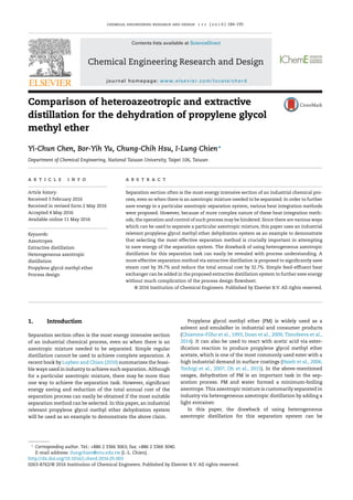
- 2. chemical engineering research and design 1 1 1 ( 2 0 1 6 ) 184–195 185 revealed by simply drawing the material balance lines with the help of simulation tool giving the residual curve maps, liquid–liquid envelope and tie lines. Another design flowsheet via extractive distillation will be proposed for this separation task. By adding a suitable heavy entrainer into the separation system without introducing additional azeotrope, the relative volatility of the original mixture can be greatly enhanced, thus, a two-column system can be designed to separate PM and water. This ternary vapor–liquid equilibrium diagram belongs to a so-called 1.0-1a in Serafimov’s classification (Serafimov, 1970). There are large numbers of paper in open literatures proposed to study this 1.0-1a extractive distillation system to separate azeotropic mixtures (e.g. Laroche et al., 1991; Arifin and Chien, 2008; Kossack et al., 2008; Luyben, 2008; Gutiérrez-Guerrz et al., 2009; Rodríguez-Donis et al., 2009; Hsu et al., 2010; Shen et al., 2013; Petlyuk et al., 2015). Some papers also described of adjusting operating pressure in the extractive-distillation system to improve separation efficiency (e.g. Luyben and Chien, 2010; Luo et al., 2014; You et al., 2015, 2016). However, to the best of our knowledge; none of the paper in open literature has investigated into this separation sys- tem. Other light or intermediate boiling entrainers may also be added (Laroche et al., 1991), however, a heavy entrainer is most common and will be proposed for this separation task. 2. Separation via heterogeneous azeotropic distillation An industrial relevant separation problem is to obtain propyl- ene glycol methyl ether (PM) from a diluted aqueous solution. The composition of the PM in the fresh feed stream is at 7.8 mol% with the rest to be water. The feed flow rate is assumed to be 1000 kmol/h. The desired product specification of PM is set to be 99.9 mol%. For the following simulation studies conduct in this paper, The NRTL thermodynamic model is selected to describe the non-ideal vapor–liquid and vapor–liquid–liquid behav- ior in the studied system and the HOC model (Hayden and O’Connell, 1975) is used to account for non-ideality in vapor phase. The Aspen built-in NRTL parameters for the PM–water pair were not satisfactory to describe the VLE experimental data as published by Tochigi et al. (2007). Therefore, parameter regression was conducted to obtain the suitable NRTL param- eters for this pair. It is shown in Fig. 1 that the T–xy plots at three operating pressures (93.3 kPa, 53.3 kPa and 26.7 kPa) are all predicted quite well using the obtained parameters. For other component pairs which do not have any experimental data, UNIFAC group contribution method was used to estimate the NRTL parameters. All NRTL parameters used in this paper are listed in Table 1. In a particular chemical plant, isopropyl acetate (iPrAc) was used as a light entrainer for this separation system via hetero- geneous azeotropic distillation. As shown in Fig. 2, the design flowsheet includes a preconcentrator column and a hetero- geneous azeotropic distillation column. The purpose of the preconcentrator column is to remove portions of water in the fresh feed through column bottoms. The limiting distil- late composition of this preconcentrator column will approach azeotropic composition of PM–water. In practice, the actual distillate composition is an important design variable to bal- ance the costs associated with the preconcentrator column and the heterogeneous azeotropic column. Fig. 1 – T–xy plots of PM–water system at various operating pressures.
- 3. 186 chemical engineering research and design 1 1 1 ( 2 0 1 6 ) 184–195 Table 1 – NRTL model parameters of the studied systems. Comp. i PM PM iPrAc PM Water Comp. j Water iPuAc Water Sulfolane Sulfolane Source From plant From plant From plant UNIFAC estimated ASPEN VLE-IG aij −1.530 0 0 0 0 aji 7.626 0 0 0 0 bij (K) 431.045 −60.437 186.759 −126.099 432.733 bji (K) −1998.746 338.092 1483.132 −270.389 333.416 cij 0.3 0.3 0.2 0.3 0.3 Comp. i PM Water PM Water Comp. j NMP NMP DMSO DMSO Source UNIFAC estimated ASPEN VLE-IG UNIFAC estimated ASPEN VLE-IG aij 1.844761 7.4081 0 −1.2449 aji −0.50235 −2.2438 0 1.7524 bij (K) −949.405 −2279.96 −150.833 586.801 bji (K) 26.03436 533.8474 −211.593 −1130.22 cij 0.3 0.3 0.3 0.3 Aspen Plus NRTL: ln i = j xijiGji k xkGki + j xiGji k xkGki ij − m xmmiGmj k xkGkj where : Gij = exp(−˛ijij) ij = aij + bij T ˛ij = cij, ii = 0, Gii = 1 Fig. 2 – RCM, LLE, material balance lines and conceptual design flowsheet via heterogeneous azeotropic distillation.
- 4. chemical engineering research and design 1 1 1 ( 2 0 1 6 ) 184–195 187 Fig. 3 – Design flowsheet via heterogeneous azeotropic distillation for the studied separation system. This distillate stream is fed into a heterogeneous azeotropic column. By adding isopropyl acetate (iPrAc) into the system, an additional azeotrope is formed that has the minimum azeotropic temperature of 76.46 ◦C in the system. This azeotrope is also inside the VLLE envelope. With the aid of iPrAc into the column through an organic reflux stream, the bottom composition can approach pure PM composition and the column top vapor can approach the lowest temperature of the ternary system, which is the azeotropic composition of iPrAc-water. This azeotrope is heterogeneous. Thus by condensing and cooling the top vapor to 40 ◦C and feed the condensate to a decanter, natural liquid–liquid separation into an organic phase and an aqueous phase will occur. The organic phase, which is rich in iPrAc, is recycled back to the heterogeneous azeotropic column. The composition of the aqueous phase is pure enough and drawn out of the system as aqueous product. A small entrainer makeup stream is needed to feed into the system at the decanter to balance the small iPrAc loss from the outlet streams. The material balance lines for the two columns (shown in Fig. 2) clearly explain the conceptual design of this separation flowsheet. With process understanding of the separation principle, it can be revealed by the lever rule that the top vapor flow rate of the heterogeneous azeotropic column will be much greater than that of its bottom flow rate. This large top vapor flow rate can be estimated by the large ratio of (b/a) in Fig. 2. In order to generate such a large top vapor flow rate, the reboiler duty must be quite high resulting in potentially in-efficient separa- tion by using this separation method. The design flowsheet of this plant in Fig. 3 showed that the reboiler duty of second col- umn is at 11,870 kW. This heterogeneous azeotropic column will be used as a base case for comparison with an improved design proposed later in this paper. From Fig. 3, it is shown that the feed composition to the heterogeneous azeotropic column was determined to be 19.17 mol% PM to balance the costs associated with the two columns. The feed flow rate is at 403.8 kmol/h. This feed condition will be set to be exactly the same in the following investigations for fair comparison. It is possible to further save the energy requirement of preconcentrator column by heat integration methods, e.g. via multi-effect distillation. However, this is beyond the scope of this paper and will not be investigated further. 3. Separation via extractive distillation system Even without conducting any rigorous simulation, it is demon- strated that the potential drawback of using heterogeneous azeotorpic distillation for the separation of this PM–water mixture can be revealed with ternary diagram of the stud- ied system including the information of residual curve maps, liquid–liquid envelope with tie lines, and material balance lines. Another separation method for azeotropic mixture will be investigated in this section by adding a heavy entrainer into the system via extractive distillation. 3.1. Entrainer selection The most important decision in this design is to choose a most effective entrainer in order to greatly enhance the relative volatility of water (lighter component) vs. PM (heavier compo- nent). Chapter 10 in Luyben and Chien (2010) used isovolatility and equivolatility curves to compare candidate entrainers. An even easier plot to generate using simulation tool is shown in Fig. 4. In this plot, the starting composition is set as the feed K(Water)/K(PM) Entrainer/Azeotrope Feed Ratio 0.0 0.5 1.0 1.5 2.0 2.5 3.0 Relative Volatility 0 2 4 6 8 10 12 14 DMSO NMP Sulfolane Fig. 4 – Enhancement of relative volatility for the candidate heavy entrainers at 1 atm.
- 5. 188 chemical engineering research and design 1 1 1 ( 2 0 1 6 ) 184–195 composition of heterogeneous azeotropic column in the last section. By gradually adding entrainer into the system, we can perform a bubble-point calculation in a flasher to obtain the enhancement of relative volatility at various feed ratio. The potential candidates are screened from some common heavy entrainers in Gmehling and Möllmann (1998). Fig. 4 demon- strates that sulfolane (SUL) or N-methyl-2-pyrrolidone (NMP) are much more effective entrainers as compared to dimethyl sulfoxide (DMSO) for this separation system. This figure can also be used to determine the distillate products in the two-column system. By observing the rela- tive volatility of water over PM to be greater than one in Fig. 4, one would know that water should be the distillate product of extractive distillation column and PM should be the distillate product of recovery column. If PM were the distillate product of extractive distillation column, the relative volatility of water over PM should become less than one by adding the candidate entrainer. Other factors that affect the entrainer performance are the y–x or T–xy plots. The y–x or T–xy plots for the water-entrainer pair can be used to determine the ease of separation in the rectifying section of extractive distillation column. The y–x or T–xy plots for the PM-entrainer pair can be used to determine if the separation in the entrainer recovery column is easy or not. Of course, thermally stable, nontoxic, low price, and other favorable physical properties should also be considered in the selection of proper entrainer. The T–xy plots of the two potential entrainers (SUL and NMP) versus water or PM are shown in Fig. 5. It is observed that the separations of water-entrainer or PM-entrainer are all fairly easy. One problem by using sulfolane as entrainer is that the temperature in the reboiler of entrainer recovery column is very high if this column operated at atmospheric pressure. If the assumption of the high-pressure steam is at 41 barg (254 ◦C), this column has to be operated at vacuum pressure. In Fig. 5, it can be seen that by setting the top pres- sure of this column at 0.06 atm, cooling water can still be used in the condenser and high-pressure steam can be used in the reboiler. As for the NMP case, there is no problem to operate this column at atmospheric pressure. 3.2. Extractive distillation system using sulfolane as entrainer (P2 at vacuum) Since sulfolane is the entrainer which can enhance the relative volatility the most, we will investigate its performance first. In an extractive distillation system, there are two columns. The first column is an extractive distillation column with both fresh feed and entrainer feeding into this column. The feed location of the entrainer is normally higher because the entrainer is heavy, while that of the fresh feed location is lower. In the column section between two feed locations (called extractive section), the concentration of entrainer is high so that water will go up the column because of the enhancement of its relative volatility while that of PM will go down with the entrainer. In the second entrainer recovery column, the PM and entrainer are separated to obtain top PM product and bot- tom entrainer. This bottom stream can be recycled back to the extractive distillation column. A cooler is normally placed in this recycle loop so that the entrainer feed temperature is 10 K below the top temperature of extractive distillation column as suggested by Doherty and Malone (2001). A small entrainer makeup stream is also necessary to balance the small loss of entrainer through two outlet streams. Table 2 – Basis of economics and equipment sizing. Column diameter (D): Aspen tray sizing Column length (L): NT trays with 2-ft spacing plus 20% extra length Column and other vessel (D and L are in meters) Capital cost = 17,640(D)1.066 (L)0.802 Condensers (area in m2 ) Heat-transfer coefficient = 0.852 kW/K m2 Differential temperature = reflux-drum temperature − 315 K Capital cost = 7296(area)0.65 Reboilers (area in m2 ) Heat-transfer coefficient = 0.568 kW/K m2 Differential temperature = steam temperature − base temperature Capital cost = 7296(area)0.65 Heat exchangers (area in m2 ) Heat-transfer coefficient = 0.852 kW/K m2 Differential temperature = LMTD of (inlet and outlet temperature differences) Capital cost = 7296(area)0.65 Water coolers (area in m2 ) Heat-transfer coefficient = 0.852 kW/K m2 Differential temperature = LMTD of (inlet or outlet temperature − 315 K) Capital cost = 7296(area)0.65 Energy cost HP steam = $9.88/GJ (41 barg, 254 ◦ C) MP steam = $8.22/GJ (10 barg, 184 ◦ C) LP steam = $7.78/GJ (5 barg, 160 ◦ C) Cooling water = $0.354/GJ Electricity = $16.9/GJ TAC = (capital cost/payback period) + energy cost Payback period = 3 year There are quite a few design variables that need to be determined in this flowsheet. The most important one is the entrainer feed flow rate (or the ratio between entrainer and fresh feed). When this entrainer feed flow rate is larger, the enhancement of the relative volatility is greater which can cut the costs associated with the extractive distillation col- umn. However, larger entrainer feed flow rate will increase the loading of second column, hence to increase the costs associ- ated with the entrainer recovery column. The proposed design flowsheet will be established next to find a low total annual cost of this two-column system. The TAC of the overall system includes the annualized cap- ital costs and the operating costs. The annualized capital costs include: costs of two columns, two reboilers, two condensers and a cooler. The payback period was assumed to be 3 years in the calculation. The operating costs include: steam for two reboilers, cooling water for two condensers and a cooler, and also a very small entrainer makeup cost. Note that to be more accurate in the TAC calculation, the costs associated with the vacuum system to generate operating pressure at a vacuum pressure should also be included. However, by following the procedure outlined on page 589–590 of Seider, et al.’s book (Seider et al., 2009), the annualized capital cost of the liquid- ring vacuum pump and also the annual electricity cost of this vacuum system can be neglected in comparison with other main terms in the TAC calculation. The bases for calculating all terms in TAC were mainly adopted from Chapter 5 of Luyben’s book (Luyben, 2011) and are summarized in Table 2. Sequential iterative procedure was used to obtain the pro- posed design flowsheet with the procedure outlined in Fig. 6. At each entrainer flow rate, the other design variables for
- 6. chemical engineering research and design 1 1 1 ( 2 0 1 6 ) 184–195 189 Fig. 5 – T–xy plots of entrainer-PM and entrainer-water. the extractive distillation column are determined first. These design variables include: total stages of extractive distilla- tion column (NT1), fresh feed location (NF1), and entrainer feed location (NFE). After these three design variables are determined at each entrainer flow rate, the design vari- ables associated with the entrainer recovery column can be determined next. Since the boiling temperature of sulfolane at 1 atm is quite high (at 560 K), even high-pressure steam in Table 2 cannot be use in the reboiler of this column. Thus, it is preferable to operate this column at vacuum pressure. This top pressure is an important design variable for this column. If it is too low, the diameter of the column will increase which
- 7. 190 chemical engineering research and design 1 1 1 ( 2 0 1 6 ) 184–195 Fig. 6 – Flowchart of iterative sequential optimization procedure. raises the capital cost of this column. However, if this top pres- sure is set to be too high, the temperature difference between the high-pressure steam and the reboiler temperature will be small which will increase capital cost of the reboiler. The two other design variables are the total stages and the feed location of the entrainer recovery column. As for top pressure of the extractive distillation column, it was conveniently set to be at atmospheric pressure for easier column operation. However, if a plot similar to Fig. 4 reveals that the enhancement of relative volatility is much greater when the operating pressure is reduced, a more suitable vac- uum pressure should be an extra design variable need to be investigated to minimize the total annual cost. Note that the lowest pressure in the investigation should be the one which can still result in boiling-point temperature of water to be 90 100 110 120 130 140 150 2300 2320 2340 2360 2380 2400 Overall TAC FE flowrate (kmol/h) Overall TAC (1000$) Fig. 7 – Summarized TAC plots at various entrainer feed rates (sulfolane as entrainer). greater than 320 K so that cheap cooling water can be used in the condenser. In this study, lowering the pressure did not see significant enhancement of relative volatility of water over PM by adding sulfolane into the system. By collecting the optimized results at each entrainer flow rate, a summarized plot of overall TAC which includes the TAC for the two columns and also the cost associated with the cooler and the makeup cost can be seen in Fig. 7. The optimized entrainer flow rate is at 110 kmol/h, this gives the entrainer-to-feed ratio of only at 0.27. At this entrainer flow rate, the detail plots associated with the extractive distilla- tion column can be seen in Fig. 8. It is shown that total stages should be 26 with the two feed locations at: NF1 = 17 and NFE = 3. Also at this entrainer flow rate the detail plots associ- ated with the entrainer recovery column can be seen in Fig. 9. Note that the optimized top pressure of this column should be at 0.06 atm, with total stages to be 9 and feed location at 4th stage. The final optimized design flowsheet is shown in Fig. 10. All itemized TAC terms are given in Table 3. The economic comparison of this design flowsheet to the heterogeneous azeotropic column in Fig. 3 will be discussed in Section 3.4. The liquid composition profiles of the two columns are shown in Fig. 11. It is observed that high concentration of sul- folane in the extractive section is necessary to prevent PM to go up the column. The separation of water and sulfolane in the rectifying section of extractive distillation column is rather easy, thus, only two stages are required. The separation of PM and sulfolane is also easy with only nine stages needed for the second column. 3.3. Extractive distillation system using NMP as entrainer (P2 = 1 atm) From the plot of relative volatility for various entrainers in Fig. 4, NMP can also enhance the relative volatility of water versus PM to some extent. The advantage of NMP over sulfolane is that NMP’s boiling temperature at 1 atm is consid- erably lower (at 478 K). This means that the entrainer recovery column of this system can be operated at atmospheric pres- sure and still able to use high-pressure steam as heat source of reboiler. There is no need to operate the second column at vacuum pressure, thus avoiding the tendency of increasing column diameter at lower operating pressure.
- 8. chemical engineering research and design 1 1 1 ( 2 0 1 6 ) 184–195 191 2 3 4 5 6 1880 1900 1920 1940 NFE TAC1 (1000$) FE=110kmol/h, NT1=24 NF1=15 NF1=16 NF1=17 2 3 4 5 6 1880 1900 1920 1940 NFE TAC1 (1000$) FE=110kmol/h, NT1=25 NF1=15 NF1=16 NF1=17 NF1=18 2 3 4 5 6 1880 1900 1920 1940 NFE TAC1 (1000$) FE=110kmol/h, NT1=26 NF1=16 NF1=17 NF1=18 2 3 4 5 6 1880 1900 1920 1940 NFE TAC1 (1000$) FE=110kmol/h, NT1=27 NF1=16 NF1=17 NF1=18 NF1=19 23 24 25 26 27 28 1885 1886 1887 1888 1889 1890 FE=110kmol/h NT1 TAC1 (1000$) Fig. 8 – Detailed plots of the extractive distillation column at FE = 110 kmol/h (sulfolane as entrainer). Table 3 – Itemized TAC terms of various design cases. Heterogeneous azeotropic distillation column Extractive distillation (sulfolane as solvent) P2 = 0.06 atm Extractive distillation (NMP as solvent) P = 1 atm C1 C2 C1 C2 Annualized column capital cost 1000$/year 101.35 123.12 43.04 226.14 64.44 Annualized reboiler capital cost 1000$/year 111.46 170.26 20.63 339.24 41.04 Annualized condenser capital cost 1000$/year 100.91 44.68 73.39 54.61 19.04 Steam cost 1000$/year 2912.28 1487.06 268.19 1880.11 556.26 Condenser cooling water cost 1000$/year 129.13 58.73 14.75 73.69 19.58 Reboiler duty MW 11.87 5.74 0.86 7.25 1.79 Annualized decanter capital cost 1000$/year 94.98 – – Annualized cooler capital cost 1000$/year – 9.86 13.94 Cooler cooling water cost 1000$/year – 8.32 15.03 Makeup cost 1000$/year 0.02 0.01 0.09 Total reboiler duty MW 11.87 6.60 9.04 Total steam cost 1000$/year 2912.28 (0%) 1755.24 (−39.7%) 2436.37 Annualized total capital cost 1000$/year 408.71 (0%) 484.98 (+18.6%) 758.45 TAC 1000$/year 3450.14 (0%) 2322.02 (−32.7%) 3303.12
- 9. 192 chemical engineering research and design 1 1 1 ( 2 0 1 6 ) 184–195 Fig. 9 – Detailed plots of the entrainer recovery column at FE = 110 kmol/h (sulfolane as entrainer). The same iterative sequential optimization procedure as outlined in Fig. 6 was used for this system. The resulting opti- mized design flowsheet by using NMP as entrainer can be seen in Fig. 12. Notice that the optimized entrainer flow rate has to be increased from 110 kmol/h to 170 kmol/h. Even with this higher entrainer flow rate, the total stages and the stages of the extractive section are much greater as compared to the result in Fig. 10. This is because of not enough enhancement of relative volatility resulting in requiring larger stages to meet stringent purity specifications. All itemized TAC terms of this system are also given in Table 3. It is quite obvious that this system cannot compete with the design flowsheet in Fig. 10. 3.4. Comparison of separation using extractive distillation (with SUL as entrainer) vs. heterogeneous azeotropic distillation (with iPrAc as entrainer) In this section, the alternative design flowsheets in Figs. 3 and 10 will be compared. As explained in Section 2, the draw- back of separation via heterogeneous azeotropic distillation Fig. 10 – Proposed design flowsheet of this studied system via extractive distillation (sulfolane as entrainer).
- 10. chemical engineering research and design 1 1 1 ( 2 0 1 6 ) 184–195 193 0 5 10 15 20 25 0.0 0.2 0.4 0.6 0.8 1.0 0 2 4 6 8 10 0.0 0.2 0.4 0.6 0.8 1.0 C2 Composition Profile C1 Composition Profile Liquid Mole Fraction (-) C1 Stages PM Water Sul Liquid Mole Fraction (-) C2 Stages PM Sul Fig. 11 – Liquid composition profiles of the two columns in Fig. 10. for this separation system can be revealed by simply drawing the material balance lines with the help of simulation tool giving the residual curve maps, liquid–liquid envelope and tie lines. The results from rigorous simulations confirmed the shortcomings of heterogeneous azeotropic distillation. Although in Fig. 3, only one column was shown to obtain the main product of PM at 99.9 mol%. However, the purity of aqueous outlet product (99.36 mol%) was lower than that of the water product in Figs. 10 and 11 (99.9 mol%). Thus, another column should be needed to further purify this aqueous out- let product for fair comparison. Even at this lower water purity in the heterogeneous azeotropic distillation column of Fig. 3, the reboiler duty (11,870.4 kW) is much greater than the total reboiler duty in Fig. 10 (5736.53 + 860.74 = 6597.3 kW). By adjusting the price difference of different steam grades, the steam cost of the extractive distillation system using sulfolane as entrainer is still much lower than that of the heterogeneous azeotropic distillation system. The details of the itemized TAC of all the alternative separation systems for this application can be found in Table 3. From Table 3, it is shown that steam cost is the dominant one in all the itemized TAC terms. The proposed design of extractive distillation system in Fig. 10 can reduce the steam cost by 39.7% as compared to the heterogeneous azeotorpic distillation column in Fig. 3. Although the annualized capital cost of the proposed design is a little higher than the heteroge- neous azeotropic distillation column, the TAC of the propose design is still significantly lower (32.7%) than that of the base case design in Fig. 3. In this analysis, the payback period of the capital cost was assumed to be 3 years. If a longer pay- back period is assumed, the reduction of the TAC can even be greater. 3.5. Proposed design using sulfolane as entrainer with simple further heat integration It is illustrated that by just selecting a more appropriate separation method, the steam cost and the TAC of this PM dehydration process can significantly be reduced without introducing any complication in the design configurations via process intensification technology. In this section, a simple heat integration method is applied to the proposed extractive distillation system in Fig. 10. Since the bottom temperature of entrainer recovery col- umn is high, a feed-effluent heat exchanger can be added to transform the energy in this hot stream to fresh feed. In this way, the reboiler duty of extractive distillation column can be reduced. This added heat exchanger is designed so that the minimum approach temperature is at 10 K. Since the temper- ature of this entrainer recycle stream is not cooled down to 90 ◦C as originally designed, another small cooler can fulfill this task. The design flowsheet by just adding a feed-effluent heat exchanger can be seen in Fig. 13. Applying this simply heat integration concept, the total steam cost can be reduced from $1.755 × 10⁶ in Fig. 10 to $1.598 × 10⁶ using the flowsheet in Fig. 13. With the calcula- tion formula of installed capital cost in Table 2, the additional capital investment of this extra heat exchanger is only at Fig. 12 – Design flowsheet via extractive distillation using NMP as entrainer.
- 11. 194 chemical engineering research and design 1 1 1 ( 2 0 1 6 ) 184–195 Fig. 13 – Proposed design with simple heat integration (sulfolane as entrainer). $4.89 × 10⁴. This means that the payback period of this addi- tional capital investment is only 0.31 year. Also, this simple heat integration configuration will not lose any important control degree-of-freedom in the system. With the broad investigation of the control strategy of extractive distillation system in open literature, there would not be any foreseeable problem in maintaining the two product purities in the face of feed flow rate and feed composition disturbances. Another energy-saving design is to thermally-coupled the two-column system (in Fig. 10). In order to combine the two reboilers, a vapor sidedraw from the second column needs to be fed to the bottom of extractive distillation column in order to provide vapor traffic in this column. However in our pro- posed system as in Fig. 10, an expensive compressor needs to be installed so that vapor sidedraw can then be fed from a vacuum pressure to a higher pressure. Since it is quite obvious that the alternative design by thermally-coupled this two- column system will not be economical, we did not investigate this energy-saving option any further. 4. Conclusions In this paper, an industrial relevant separation process of dehydrating propylene glycol methyl ether was investigated. The common way for this separation system is to utilize a light entrainer (in this case, isopropyl acetate) via heteroge- neous azeotropic distillation. Even without conducting any rigorous simulation, it is demonstrated in this paper that the potential drawback of using this separation method can be revealed with ternary diagram of the studied system including the information of residual curve maps, liquid–liquid envelope with tie lines, and material balance lines. By using a different separation method via extractive distil- lation, it is demonstrated that significant reduction in steam cost of 39.7% and TAC cut by 32.7% can be realized by the pro- posed design in Fig. 10. Sulfolane was found to be the effective heavy entrainer to greatly enhance the relative volatility of water versus PM. A simple further heat integration method can be applied to the proposed extractive distillation system to further cut the steam cost by 8.9% without introducing much complication into the design flowsheet. This investigation is appropriate as in the conceptual design stage of a particular separation process. To make sure about the ternary vapor–liquid equilibrium behavior of this separation system for the enhancement of relative volatil- ity, further thermodynamic experimental evaluation of this PM–water–sulfolane ternary mixture should be conducted so that detail design of this separation process can be followed. Acknowledgement The research funding from the Ministry of Science and Tech- nology of R.O.C. under grant no. MOST 104-2221-E-002-187 is greatly appreciated. References Arifin, S., Chien, I.L., 2008. Design and control of an isopropy alcohol dehydration process via extractive distillation using dimethyl sulfoxide as an entrainer. Ind. Eng. Chem. Res. 47, 790–803. Chiavone-Filho, O., Proust, P., Rasmussen, P., 1993. Vapor–liquid equilibria for glycol ether + water systems. J. Chem. Eng. Data 38, 128–131. Doan, H.D., Weli, A., Wu, J., 2009. A combined photocatalytic and electrochemical treatment of wasterwater containing propylene glycol methyl ether and metal ions. Chem. Eng. J. 151, 51–58. Doherty, M.F., Malone, M.F., 2001. Conceptual Design of Distillations. McGraw-Hill, New York, pp. 183–256. Gmehling, J., Möllmann, C., 1998. Synthesis of distillation processes using thermodynamic models and the Dortmund data bank. Ind. Eng. Chem. Res. 37, 3112–3123. Gutiérrez-Guerrz, R., Segovia-Hernández, J.G., Hernández, S., 2009. Reducing energy consumption and CO2 emissions in extractive distillation. Chem. Eng. Res. Des. 87, 145–152. Hayden, J.G., O’Connell, J.P., 1975. A generalized method for predicting second virial coefficients. Ind. Eng. Chem. Process Des. Dev. 14, 209–216. Hsieh, C.T., Lee, M.J., Lin, H.M., 2006. Multiphase equilibria for mixtures containing acetic acid, water, propylene glycol monomethyl ether, and proylene glycol methyl ether acetate. Ind. Eng. Chem. Res. 45, 2123–2130. Hsu, K.Y., Hsiao, Y.C., Chien, I.L., 2010. Design and control of dimethyl carbonate-methanol separation via extractive
- 12. chemical engineering research and design 1 1 1 ( 2 0 1 6 ) 184–195 195 distillation in the dimethyl carbonate reactive-distillation process. Ind. Eng. Chem. Res. 49, 735–749. Kossack, S., Kramer, K., Gani, R., Marquardt, W., 2008. A systematic synthesis framework for extractive distillation processes. Chem. Eng. Res. Des. 86, 781–792. Laroche, L., Bekiaris, N., Andersen, H.W., Morari, M., 1991. Homogeneous azeotropic distillation. Comparing entrainers. Can. J. Chem. Eng. 69, 1302–1319. Luo, H., Liang, K., Li, W., Xia, M., Xu, C., 2014. Comparison of pressure-swing distillation and extractive distillation method for isopropyl alcohol/diisopropyl ether separation. Ind. Eng. Chem. Res. 53, 15167–15182. Luyben, W.L., 2008. Comparison of extractive distillation and pressure-swing distillation for acetone-methanol separation. Ind. Eng. Chem. Res. 47, 2696–2707. Luyben, W.L., Chien, I.L., 2010. Design and Control of Distillation Systems for Separating Azeotropes. Wiley, Hoboken, NJ. Luyben, W.L., 2011. Principles and Case Studies of Simultaneous Design. Wiley, Hoboken, NJ. Oh, J., Agrawal, G., Sreedhar, B., Donaldson, M.E., Schultz, A.K., Frank, T.C., Bommarius, A.S., Kawajiri, Y., 2015. Conversion improvement for catalytic synthesis of propylene glycol methyl ether acetate by reactive chromatography: experiments and parameter estimation. Chem. Eng. J. 259, 397–409. Petlyuk, F., Danilov, R., Burger, J., 2015. A novel method for the search and identification of feasible splits of extractive distillations in ternary mixtures. Chem. Eng. Res. Des. 99, 132–148. Rodríguez-Donis, I., Gerbaud, V., Joulia, X., 2009. Thermodynamic insights on the feasibility of homogeneous batch extractive distillation. 1. Azeotropic mixtures with heavy entrainer. Ind. Eng. Chem. Res. 48, 3544–3559. Seider, W.D., Seader, J.D., Lewin, D.R., Widagdo, S., 2009. Product and Process Design Principles, 3rd ed. Wiley, Hoboken, NJ. Serafimov, L.A., 1970. The azeotropic rule and the classification of multicomponent mixtures. VII. Diagrams for ternary mixtures. Russ. J. Phys. Chem. 44, 567–571. Shen, W., Benyounes, H., Gerbaud, V., 2013. Extension of thermodynamic insights on batch extractive distillation to continuous operation. 1. Azeotropic mixtures with a heavy entrainer. Ind. Eng. Chem. Res. 52, 4606–4622. Timofeeva, M.N., Panchenko, V.N., Matrosova, M.M., Andreev, A.S., Tsybulya, S.V., Gil, A., Vicente, M.A., 2014. Factors affecting the catalytic performance of Zr, Al-pillared clays in the synthesis of propylene glycol methyl ether. Ind. Eng. Chem. Res. 53, 13565–13574. Tochigi, K., Takahara, H., Shiga, Y., Kawase, Y., 2007. Isobaric vapor–liquid equilibria for water + propylene glycol monomethyl ether (PGMA), water + proplyleneglycol monomethyl ether acetate (PGMEA), and PGME + PGMEA and reduced pressures. Fluid Phase Equilib. 260, 65–69. You, X.Q., Rodríguez-Donis, I., Gerbaud, V., 2015. Improved design and efficiency of the extractive distillation process for acetone-methanol with water. Ind. Eng. Chem. Res. 54, 491–501. You, X.Q., Rodríguez-Donis, I., Gerbaud, V., 2016. Reducing process cost and CO2 emissions for extractive distillation by double-effect heat integration and mechanical heat pump. Appl. Energy 166, 128–140.