1. BusWorks ™
900MB Series
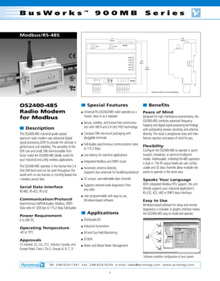
Modbus/RS-485
4.13 2.24
(104.9) (56.9)
RS-232
ANT A ANT B
PWR
LINK
3.39
TxD
(86.1)
RxD
232 4.26
485 (108.2)
R T C T R
6-28VDC 6W x x O x x
D D M D D RS-485
+ - 485 232 + + - -
Dimensions shown in inches (millimeters).
OS2400-485 s Special Features s Benefits
Radio Modem s Universal RS-232/422/485 radio operates as a Peace of Mind
master, slave or as a repeater Designed for high interference environments, the
for Modbus
s Secure, wireless, and license-free communica- OS2400-485 combines advanced frequency
tion with ARC4 and 2.4 GHz FHSS technology hopping and digital signal processing technology
s Description with outstanding receiver sensitivity and antenna
The OS2400-485 industrial grade spread s Compact DIN rail-mount packaging with diversity. The result is exceptional noise and inter-
spectrum radio modem uses advanced digital pluggable terminals ference rejection and peace of mind for you.
signal processing (DSP) to provide the ultimate in s Full-duplex asynchronous communication rates
performance and reliability. The versatility of the Flexibility
to 115.2 Kbps
DSP core and small, DIN rail-mountable form Configure the OS2400-485 to operate in point-
factor make the OS2400-485 ideally suited for s Low latency for real-time applications to-point, broadcast, or point-to-multipoint
your industrial and utility wireless applications. modes. Addressable, multidrop RS-485 operation
s Integrated Modbus and DNP3 router
is built in. The RF output levels are user config-
The OS2400-485 operates in the license-free 2.4 s Automatic antenna diversity urable and 32 data channels allow multiple net-
GHz ISM band and can be used throughout the (supports two antennae for local/long-distance) works to operate in the same area.
world with no site licenses or monthly leased line
/ wireless service fees. s 32 unique, user-selectable data channels Speaks Your Language
s Supports network-wide diagnostics from With integrated Modbus RTU support, this unit
Serial Data Interface directly supports your industrial application’s
any radio
RS-485, RS-422, RS-232 RS-232, 422, 485 or DNP3 data interfaces.
s User programmable with easy to use,
Communication/Protocol Windows-based software Easy to Use
Asynchronous half/full-duplex, Modbus, DNP3. Windows-based software for setup and remote
Data rates of 1200 bps to 115.2 Kbps full-duplex. diagnostics is included. A graphic interface makes
s Applications the OS2400-485 easy to install and operate.
Power Requirement
6 to 28V DC s Distributed I/O
s Industrial Automation
Operating Temperature
-40 to 75°C s Oil and Gas Field Monitoring
Approvals s SCADA
CE marked. UL, cUL, FCC, Industry Canada, and s Water and Waste Water Management
Europe listed. Class I, Div 2, Groups A, B, C, D
Software simplifies configuration of your system.
Tel: 248-624-1541 Fax: 248-624-9234 e-mail: sales@acromag.com www.acromag.com
1
2. BusWorks ™
900MB Series
s Ordering Info
RS-485
PWR
LINK
RxD
TxD
232
485
TX RX
+
R
D
+
x
RS-232
+
PC
D
T
+
x
COM
M
O
C
Modems
RX TX
-
D
T
x
PLC
-
R
D
-
x
-
MASTER
ANT B
DCS
MODEM
485 232
OS2400-485-SK1*
Starter Kit #1-US and Canada
6-28VDC 6W
ANT A
+ -
+ -
Includes: 2 each OS2400-485-1 modems
OS2400-485-SK2*
Starter Kit #2-Europe
Basic
RS-485
TB3
Includes: 2 each OS2400-485-2 modems
PWR
LINK
31
RxD
TxD
A
232
485
PWR
TX RX
32
B
+
900MB
R
D
+
x
RS-232
33
D
+
M D
C T
+
O x
System
COM
RS-485
D
34
MODULE
OS2400-485-1§
RX TX
COM
35
D
-
T
x
-
36
COM
R
D
-
x
-
ANT B
TB3
TB1
TB4
SLAVE
Diagram Radio frequency modem: US and Canada
485 232
41
16
MODEM
42
15
43
14
44
13
45
12
OS2400-485-2§
6-28VDC 6W
ANT A
46
11
TB4 TB1
+ -
+ -
Radio Modem: Europe
* Each kit also includes:
Two 2dbi straight antennas, one 6 ft. DB9 serial cable,
s Performance s Environmental two power supplies, software, and user’s manual (PDF)
Ambient Temperature §
Includes configuration software only, antennas and
s General Operating: -40 to 75°C.
accessories ordered separately.
Physical Humidity
114 x 105 x 59 mm (4.5” W x 4.12” H x 2.32”D). To 90% RH (noncondensing). Cables
224 grams (8 ounces). 5035-818
Power RP N bulkhead jack - RA RP SMA plug, 2 ft.
Antenna Supply Voltage: 6 to 28V DC.
Two RP SMA connectors; automatic antenna diversity. 5035-822
Power (Average): 2.5W master, 1.25W remote.
Supports two antennas for superior reception and RP RA SMA plug - RP N plug, 2 ft.
operation as a “repeater” device. Approvals
FCC listed (FCC Part 15.247). 5035-957
Typical Indoor Range RS232 communication cable, DB9, Male/Female, 6 ft.
150 to 450 meters. Industry Canada listed (RSS 210).
Europe listed (ETSI300.328, ETSI 300.826, EN60950). Antennas
Typical Outdoor Range
3+ kilometers with 2dBi omni antenna; up to 25 CSA marked (C22.2 No. 142-M1987, 213-1987). 5035-888
kilometers line of sight with high gain antennas. UL listed (UL1604 Class 1: Div. 2; Groups A,B,C,D Omni-directional straight, 2dbi, 2.4Ghz, RP SMA
Temp. Code: T4A). 5035-876
Software
Windows-based user setup, diagnostic, and Omni-directional articulating, 5dbi, 2.4Ghz, RP SMA
s Transceiver
communication software (included with Setup Kit and Characteristics 5035-880
each modem purchase). Omni-directional collinear, 8dbi, 2.4Ghz, RP N
Frequency
s Data Interface 2.4 to 2.4835 GHz for USA; varies for other countries. 5035-884
Serial Data Interface Radio Type Directional patch, 11dbi, 2.4Ghz, RP SMA
RS-485, RS-422, RS-232. Frequency hopping spread spectrum (FHSS). 5035-892
Communication Number of Frequency Channels Omni-directional antenna mounting bracket, 8dbi
Asynchronous half/full-duplex, Modbus and DNP3. 79 for USA; varies for other countries.
Lightning Protection
I/O Data Rate Output Power 5035-945
1200 bps to 115.2 Kbps full-duplex. 1 mW to 250 mW, programmable. RP N (female) jack - RP N (female) bulkhead jack
Network Topology Channel Data Rate 5035-949
Point-to-point, store & forward repeater, 250 Kbps. RP N (female) bulkhead jack - RP N (male) plug
point-to-multipoint, and peer-to-peer (DNP3 only).
Receiver Sensitivity
Hop Patterns -96 dBm @ 10-6 BER. Miscellaneous
32 user selectable, non-interfering, networks. 5035-961
Adjacent Channel Rejection Power supply, 120V AC to 12V DC w/connector
Error Detection / Correction > 40 dB.
32 bit CRC with ARQ (Automatic Re-Send Query). 5035-971
Spurious Rejection Setup and diagnostic software on CD-ROM with
Encryption > 50 dB. user’s manual (PDF format only) for OS2400-485
ARC4 (40 bit).
5035-953
Latency Antenna site survey kit
<20 ms.
Tel: 248-624-1541 Fax: 248-624-9234 e-mail: sales@acromag.com www.acromag.com
2
3. Network I/O Modules
OS2400 Antennas, Cables, and Lightning Protection
Omni-directional (2dBi) Omni-dir. Articulating (5dBi) Omni-dir. Collinear Array (8dBi) Directional Patch (11dBi)
Model 5035-888 Model 5035-876 Model 5035-880 Model 5035-884
Side view of antenna pattern Side view of antenna pattern Side view of antenna pattern Side view of antenna pattern
Choosing the Right Antenna Distance Chart Link Gain *Unobstructed
Link Gain is a composite of the gains of each of the antennas (the Master’s antenna and the The chart to the right has been adjusted to (dB) Distance
Remote’s antenna) as well as any cable loss. For example, if you want to communicate over a allow for 10dB of “margin” in your system. 35 15 mi (24.2 km)
2 mile (3.2km) unobstructed distance, you should include at least 7dB of Link Gain. This margin accounts for expected changes in 30 12 mi (19.4 km)
Master antenna gain: 8 dBi (Omni-directional xxx-xxxx) the environment during operation. 25 10 mi (16.1 km)
Remote antenna gain: 8 dBi ( ----- ) 15 5 mi (8.0 km)
Cable at the Master: -2 dBi (4 feet or ) 7 2 mi (3.2 km)
Cable at the Slave: -5 dBi (10 feet) 4 1 mi (1.6 km)
Total Link Gain: 9 dBi * Radio power set to Max.
More gain will give you more distance. It doesn’t make any difference whether the gain is on
the Master or the Remote radio. The gains of the two antennas is additive.
NOTE: Contact factory for a reference list of antenna and cable suppliers if needed.
Make the choice for each antenna pair (if you have a point-multipoint system).
Enclosure Wall
No Lightning Protection Possible Antennas
Inside of Outside of 8 dBi Omni #5035-880
Enclosure Enclosure 11 dBi Patch #5035-884
RP = Reverse Polarity
RA = Right Angle
RP N
RP RA RP N RP N
Bulkhead
SMA Plug Plug Plug
Jack
To Radio RP N Jack
Modem XXX-XXXXXX LMR400 XXX-XXXXXX on Antenna
LMR195 To Antenna
Model #5035-818 (2') Customer supplied
Lightning Protection Inside Box
Inside of Outside of Possible Antennas
Enclosure Enclosure 8 dBi Omni #5035-880
11dBi Patch #5035-884
RP RA RP N RP N
RP N RP N RP N
SMA Plug Jack Bulkhead
Plug Plug Plug
Jack
Equipment
Antenna
To Radio RP N Jack
Modem XXX-XXXXXX
LMR400 XXX-XXXXXX
on Antenna
Model #5035-822 (2') Customer Supplied To Antenna
Model #5035-949
This is typically
mounted through an
enclosure
Lightning Protection Outside Box Possible Antennas
8 dBi Omni #5035-880
Inside of Outside of
11 dBi Patch #5035-884
Enclosure Enclosure
RP RA RP N RP N
RP N
SMA Plug Bulkhead Plug
Plug
Jack RP N Jack
Equipment
on Antenna
Antenna
To Radio
XXX-XXXXXX To Antenna
Modem or with RP N Jack
Model #5035-822 (2')
Model #5035-945
LMR400
This is typically
mounted through an
enclosure RP N Jack Customer Supplied RP N
on Antenna Plug
Tel: 248-624-1541 Fax: 248-624-9234 e-mail: sales@acromag.com www.acromag.com
3