SlideShare a Scribd company logo
1 of 2
Download to read offline
P/N 3100331 ISSUE 2 © 2004
Installation Instructions for 1500 Series
Door Holder Extension Kits
Description
The Edwards 1500 Series Door Holder Extension Kits are used
where it is desired to hold doors open and where a standoff dis-
tance between the magnet assembly and the armature base is re-
quired. The extension rod kit can be used with Edwards 1504,
1505, 1508 and 1509 Series Door Holders. Parts from these door
holders are used with the extension kits to form a complete unit.
Specifications
Model Number Extension Range
1500-1 1 1/2" (38 mm) Fixed
1500-2 2" (51 mm) Fixed
1500-7 6.37 - 8.00" (162 - 203 mm)
1500-12 8.37 - 12" (213 - 305 mm)
Installation
c. Insert the extension rod into the armature base and secure
with #10-32 x 1 1/2" (38 mm) armature securing screw
(Figures 1 - 3).
d. Insert spherical bushings (supplied) and flat washers
(supplied with 1500-7 and 1500-12 only) into the
extension rod assembly as shown in Figure 2 or Figure 3,
as applicable. Secure catch plate in extension rod using
#10-32UNF x 1" (25 mm) securing screw (Figure 2).
e. For adjustable units only, adjust the extension length by
loosening the knurled locking nut, extending the rod to
the desired length and retightening the knurled locking
nut (Figure 2).
NOTE: Proper alignment of the catch plate and the
electromagnet helps ensure sufficient holding force.
f. Align the catch plate with the electromagnet by moving
the extension arm up or down and back or forth while
simultaenously adjusting the catch plate against the
magnet. There should be no gap between the catch plate
and the magnet.
g. After the desired extension length and contact alignment
have been achieved, perform the following (Figure 2):
1. Using a 5/32" (4 mm)Allen Wrench (supplied), lock
the extension arm into position by tightening the
armature securing screw (Figure 2). Do not
overtighten.
h. Perform an operational check of the Electromagnetic
Door Holder as outlined in the installation instruction
provided with the door holder.
2. For more detailed information on installation of the door
holders, see the instructions supplied with the door holder.
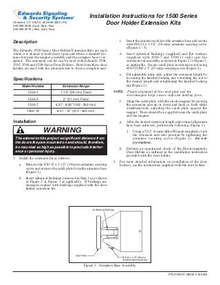
Figure 1. Armature Base Assembly
Cheshire, CT 06410 203-699-3300 (Ph)
203-699-3365 (Cust. Serv. Fax)
203-699-3078 (Tech. Serv. Fax)
WARNING
The extension kits project a significant distance from
the doors they are mounted on and should, therefore,
be mounted as high as possible to preclude interfer-
ence or personal injury.
1. Install the extension kit as follows.
a. Remove the #10-32 x 1 1/2" (38 mm) armature securing
screw and remove the catch plate from the armature base
(Figure 1).
b. Insert spherical bushings (removed in Step 1.a) as shown
in Figure 2 or Figure 3 as applicable. If bushings are
damaged, replace with bushings supplied with the door
holder extension kit.
#10-32 x 1 1/2” (38 mm)
Armature Securing Screw
(supplied with door holder)
Armature Base (supplied with door holder)
(2) Spherical Bushings
(supplied)
(2) Spherical Bushings
(supplied)
Extension Tube
Assembly
#10-32 UNF x 1“ (25 mm)
Screw (supplied)
Knurled Locking Nut
(2) Flat Washers
(supplied)
Catch Plate
(supplied with door holder)
#10-32 UNF Nut
(supplied)
Figure 2. Extension Rod Assembly (Adjustable 1500-7 and 1500-12 Model)
P/N 3100331 ISSUE 2
Catch Plate
(supplied with door holder)
Armature Base
(supplied with door holder)
(2) Spherical Bushings
(supplied)
Extension
Assembly
(2) Spherical Bushings
(supplied)
#10-32 UNF x 1" (25 mm)
Screw (supplied)
#10-32 UNF Nut
(supplied)
#10-32 x 1 1/2" (38 mm)
Armature Securing Screw
(supplied with door holder)
Figure 3. Extension Rod Assembly (Adjustable 1500-1 and 1500-2 Model)

More Related Content

More from JMAC Supply

More from JMAC Supply (20)

Bosch AE101 Data Sheet
Bosch AE101 Data SheetBosch AE101 Data Sheet
Bosch AE101 Data Sheet
 
Bosch AE4 Data Sheet
Bosch AE4 Data SheetBosch AE4 Data Sheet
Bosch AE4 Data Sheet
 
Bosch AE1 Data Sheet
Bosch AE1 Data SheetBosch AE1 Data Sheet
Bosch AE1 Data Sheet
 
Bosch ACD-IC16K37-50 Data Sheet
Bosch ACD-IC16K37-50 Data SheetBosch ACD-IC16K37-50 Data Sheet
Bosch ACD-IC16K37-50 Data Sheet
 
Bosch ACD-IC2K37-50 Data Sheet
Bosch ACD-IC2K37-50 Data SheetBosch ACD-IC2K37-50 Data Sheet
Bosch ACD-IC2K37-50 Data Sheet
 
Bosch ACA-IC2K26-10 Data Sheet
Bosch ACA-IC2K26-10 Data SheetBosch ACA-IC2K26-10 Data Sheet
Bosch ACA-IC2K26-10 Data Sheet
 
Bosch 9208B Data Sheet
Bosch 9208B Data SheetBosch 9208B Data Sheet
Bosch 9208B Data Sheet
 
Bosch 7110XC Data Sheet
Bosch 7110XC Data SheetBosch 7110XC Data Sheet
Bosch 7110XC Data Sheet
 
Samsung Techwin SNB-1000 Data Sheet
Samsung Techwin SNB-1000 Data SheetSamsung Techwin SNB-1000 Data Sheet
Samsung Techwin SNB-1000 Data Sheet
 
Samsung Techwin SMT-4031 Data Sheet
Samsung Techwin SMT-4031 Data SheetSamsung Techwin SMT-4031 Data Sheet
Samsung Techwin SMT-4031 Data Sheet
 
Samsung Techwin SMT-4023 Data Sheet
Samsung Techwin SMT-4023 Data SheetSamsung Techwin SMT-4023 Data Sheet
Samsung Techwin SMT-4023 Data Sheet
 
Samsung Techwin SMT-3232 Data Sheet
Samsung Techwin SMT-3232 Data SheetSamsung Techwin SMT-3232 Data Sheet
Samsung Techwin SMT-3232 Data Sheet
 
Samsung Techwin SMT-3231 Data Sheet
Samsung Techwin SMT-3231 Data SheetSamsung Techwin SMT-3231 Data Sheet
Samsung Techwin SMT-3231 Data Sheet
 
Samsung Techwin SMT-2232 Data Sheet
Samsung Techwin SMT-2232 Data SheetSamsung Techwin SMT-2232 Data Sheet
Samsung Techwin SMT-2232 Data Sheet
 
Samsung Techwin SMT-1934 Data Sheet
Samsung Techwin SMT-1934 Data SheetSamsung Techwin SMT-1934 Data Sheet
Samsung Techwin SMT-1934 Data Sheet
 
Samsung Techwin SMT-1914 Data Sheet
Samsung Techwin SMT-1914 Data SheetSamsung Techwin SMT-1914 Data Sheet
Samsung Techwin SMT-1914 Data Sheet
 
Samsung Techwin SMT-1734 Data Sheet
Samsung Techwin SMT-1734 Data SheetSamsung Techwin SMT-1734 Data Sheet
Samsung Techwin SMT-1734 Data Sheet
 
Samsung Techwin SLA-M3180DN Data Sheet
Samsung Techwin SLA-M3180DN Data SheetSamsung Techwin SLA-M3180DN Data Sheet
Samsung Techwin SLA-M3180DN Data Sheet
 
Samsung Techwin SLA-M2882 Data Sheet
Samsung Techwin SLA-M2882 Data SheetSamsung Techwin SLA-M2882 Data Sheet
Samsung Techwin SLA-M2882 Data Sheet
 
Samsung Techwin SLA-12240 Data Sheet
Samsung Techwin SLA-12240 Data SheetSamsung Techwin SLA-12240 Data Sheet
Samsung Techwin SLA-12240 Data Sheet
 

Recently uploaded

Easier, Faster, and More Powerful – Alles Neu macht der Mai -Wir durchleuchte...
Easier, Faster, and More Powerful – Alles Neu macht der Mai -Wir durchleuchte...Easier, Faster, and More Powerful – Alles Neu macht der Mai -Wir durchleuchte...
Easier, Faster, and More Powerful – Alles Neu macht der Mai -Wir durchleuchte...
panagenda
 

Recently uploaded (20)

Easier, Faster, and More Powerful – Alles Neu macht der Mai -Wir durchleuchte...
Easier, Faster, and More Powerful – Alles Neu macht der Mai -Wir durchleuchte...Easier, Faster, and More Powerful – Alles Neu macht der Mai -Wir durchleuchte...
Easier, Faster, and More Powerful – Alles Neu macht der Mai -Wir durchleuchte...
 
AI mind or machine power point presentation
AI mind or machine power point presentationAI mind or machine power point presentation
AI mind or machine power point presentation
 
ASRock Industrial FDO Solutions in Action for Industrial Edge AI _ Kenny at A...
ASRock Industrial FDO Solutions in Action for Industrial Edge AI _ Kenny at A...ASRock Industrial FDO Solutions in Action for Industrial Edge AI _ Kenny at A...
ASRock Industrial FDO Solutions in Action for Industrial Edge AI _ Kenny at A...
 
State of the Smart Building Startup Landscape 2024!
State of the Smart Building Startup Landscape 2024!State of the Smart Building Startup Landscape 2024!
State of the Smart Building Startup Landscape 2024!
 
A Business-Centric Approach to Design System Strategy
A Business-Centric Approach to Design System StrategyA Business-Centric Approach to Design System Strategy
A Business-Centric Approach to Design System Strategy
 
Portal Kombat : extension du réseau de propagande russe
Portal Kombat : extension du réseau de propagande russePortal Kombat : extension du réseau de propagande russe
Portal Kombat : extension du réseau de propagande russe
 
WebAssembly is Key to Better LLM Performance
WebAssembly is Key to Better LLM PerformanceWebAssembly is Key to Better LLM Performance
WebAssembly is Key to Better LLM Performance
 
TEST BANK For, Information Technology Project Management 9th Edition Kathy Sc...
TEST BANK For, Information Technology Project Management 9th Edition Kathy Sc...TEST BANK For, Information Technology Project Management 9th Edition Kathy Sc...
TEST BANK For, Information Technology Project Management 9th Edition Kathy Sc...
 
TopCryptoSupers 12thReport OrionX May2024
TopCryptoSupers 12thReport OrionX May2024TopCryptoSupers 12thReport OrionX May2024
TopCryptoSupers 12thReport OrionX May2024
 
Powerful Start- the Key to Project Success, Barbara Laskowska
Powerful Start- the Key to Project Success, Barbara LaskowskaPowerful Start- the Key to Project Success, Barbara Laskowska
Powerful Start- the Key to Project Success, Barbara Laskowska
 
AI presentation and introduction - Retrieval Augmented Generation RAG 101
AI presentation and introduction - Retrieval Augmented Generation RAG 101AI presentation and introduction - Retrieval Augmented Generation RAG 101
AI presentation and introduction - Retrieval Augmented Generation RAG 101
 
How Red Hat Uses FDO in Device Lifecycle _ Costin and Vitaliy at Red Hat.pdf
How Red Hat Uses FDO in Device Lifecycle _ Costin and Vitaliy at Red Hat.pdfHow Red Hat Uses FDO in Device Lifecycle _ Costin and Vitaliy at Red Hat.pdf
How Red Hat Uses FDO in Device Lifecycle _ Costin and Vitaliy at Red Hat.pdf
 
Simplified FDO Manufacturing Flow with TPMs _ Liam at Infineon.pdf
Simplified FDO Manufacturing Flow with TPMs _ Liam at Infineon.pdfSimplified FDO Manufacturing Flow with TPMs _ Liam at Infineon.pdf
Simplified FDO Manufacturing Flow with TPMs _ Liam at Infineon.pdf
 
PLAI - Acceleration Program for Generative A.I. Startups
PLAI - Acceleration Program for Generative A.I. StartupsPLAI - Acceleration Program for Generative A.I. Startups
PLAI - Acceleration Program for Generative A.I. Startups
 
Secure Zero Touch enabled Edge compute with Dell NativeEdge via FDO _ Brad at...
Secure Zero Touch enabled Edge compute with Dell NativeEdge via FDO _ Brad at...Secure Zero Touch enabled Edge compute with Dell NativeEdge via FDO _ Brad at...
Secure Zero Touch enabled Edge compute with Dell NativeEdge via FDO _ Brad at...
 
BT & Neo4j _ How Knowledge Graphs help BT deliver Digital Transformation.pptx
BT & Neo4j _ How Knowledge Graphs help BT deliver Digital Transformation.pptxBT & Neo4j _ How Knowledge Graphs help BT deliver Digital Transformation.pptx
BT & Neo4j _ How Knowledge Graphs help BT deliver Digital Transformation.pptx
 
Overview of Hyperledger Foundation
Overview of Hyperledger FoundationOverview of Hyperledger Foundation
Overview of Hyperledger Foundation
 
IESVE for Early Stage Design and Planning
IESVE for Early Stage Design and PlanningIESVE for Early Stage Design and Planning
IESVE for Early Stage Design and Planning
 
Enterprise Knowledge Graphs - Data Summit 2024
Enterprise Knowledge Graphs - Data Summit 2024Enterprise Knowledge Graphs - Data Summit 2024
Enterprise Knowledge Graphs - Data Summit 2024
 
FDO for Camera, Sensor and Networking Device – Commercial Solutions from VinC...
FDO for Camera, Sensor and Networking Device – Commercial Solutions from VinC...FDO for Camera, Sensor and Networking Device – Commercial Solutions from VinC...
FDO for Camera, Sensor and Networking Device – Commercial Solutions from VinC...
 

Edwards Signaling 1500-12 Installation Manual

  • 1. P/N 3100331 ISSUE 2 © 2004 Installation Instructions for 1500 Series Door Holder Extension Kits Description The Edwards 1500 Series Door Holder Extension Kits are used where it is desired to hold doors open and where a standoff dis- tance between the magnet assembly and the armature base is re- quired. The extension rod kit can be used with Edwards 1504, 1505, 1508 and 1509 Series Door Holders. Parts from these door holders are used with the extension kits to form a complete unit. Specifications Model Number Extension Range 1500-1 1 1/2" (38 mm) Fixed 1500-2 2" (51 mm) Fixed 1500-7 6.37 - 8.00" (162 - 203 mm) 1500-12 8.37 - 12" (213 - 305 mm) Installation c. Insert the extension rod into the armature base and secure with #10-32 x 1 1/2" (38 mm) armature securing screw (Figures 1 - 3). d. Insert spherical bushings (supplied) and flat washers (supplied with 1500-7 and 1500-12 only) into the extension rod assembly as shown in Figure 2 or Figure 3, as applicable. Secure catch plate in extension rod using #10-32UNF x 1" (25 mm) securing screw (Figure 2). e. For adjustable units only, adjust the extension length by loosening the knurled locking nut, extending the rod to the desired length and retightening the knurled locking nut (Figure 2). NOTE: Proper alignment of the catch plate and the electromagnet helps ensure sufficient holding force. f. Align the catch plate with the electromagnet by moving the extension arm up or down and back or forth while simultaenously adjusting the catch plate against the magnet. There should be no gap between the catch plate and the magnet. g. After the desired extension length and contact alignment have been achieved, perform the following (Figure 2): 1. Using a 5/32" (4 mm)Allen Wrench (supplied), lock the extension arm into position by tightening the armature securing screw (Figure 2). Do not overtighten. h. Perform an operational check of the Electromagnetic Door Holder as outlined in the installation instruction provided with the door holder. 2. For more detailed information on installation of the door holders, see the instructions supplied with the door holder. Figure 1. Armature Base Assembly Cheshire, CT 06410 203-699-3300 (Ph) 203-699-3365 (Cust. Serv. Fax) 203-699-3078 (Tech. Serv. Fax) WARNING The extension kits project a significant distance from the doors they are mounted on and should, therefore, be mounted as high as possible to preclude interfer- ence or personal injury. 1. Install the extension kit as follows. a. Remove the #10-32 x 1 1/2" (38 mm) armature securing screw and remove the catch plate from the armature base (Figure 1). b. Insert spherical bushings (removed in Step 1.a) as shown in Figure 2 or Figure 3 as applicable. If bushings are damaged, replace with bushings supplied with the door holder extension kit.
  • 2. #10-32 x 1 1/2” (38 mm) Armature Securing Screw (supplied with door holder) Armature Base (supplied with door holder) (2) Spherical Bushings (supplied) (2) Spherical Bushings (supplied) Extension Tube Assembly #10-32 UNF x 1“ (25 mm) Screw (supplied) Knurled Locking Nut (2) Flat Washers (supplied) Catch Plate (supplied with door holder) #10-32 UNF Nut (supplied) Figure 2. Extension Rod Assembly (Adjustable 1500-7 and 1500-12 Model) P/N 3100331 ISSUE 2 Catch Plate (supplied with door holder) Armature Base (supplied with door holder) (2) Spherical Bushings (supplied) Extension Assembly (2) Spherical Bushings (supplied) #10-32 UNF x 1" (25 mm) Screw (supplied) #10-32 UNF Nut (supplied) #10-32 x 1 1/2" (38 mm) Armature Securing Screw (supplied with door holder) Figure 3. Extension Rod Assembly (Adjustable 1500-1 and 1500-2 Model)