Fo mi 40-ds
•
0 likes•413 views

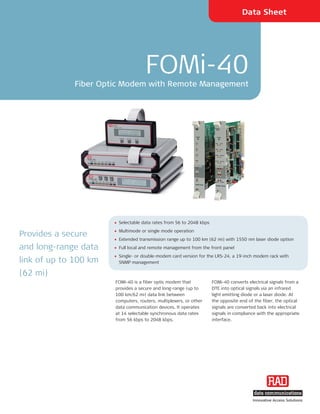
The document describes the FOMi-40 fiber optic modem, which provides long-range data transmission over fiber optic cable up to 100 km. The FOMi-40 converts electrical signals to optical signals and supports data rates from 56 to 2048 kbps. It has remote management capabilities and can operate in single or double modem configurations.

Recommended
More Related Content
What's hot
What's hot (20)
Viewers also liked
Viewers also liked (13)
Similar to Fo mi 40-ds
Similar to Fo mi 40-ds (20)
More from Ivan Nuñez Salinas
More from Ivan Nuñez Salinas (20)
Recently uploaded
Recently uploaded (20)
Fo mi 40-ds
- 1. Data Sheet FOMi-40 Fiber Optic Modem with Remote Management • Selectable data rates from 56 to 2048 kbps • Multimode or single mode operation Provides a secure • Extended transmission range up to 100 km (62 mi) with 1550 nm laser diode option and long-range data • Full local and remote management from the front panel • Single- or double-modem card version for the LRS-24, a 19-inch modem rack with link of up to 100 km SNMP management (62 mi) FOMi-40 is a fiber optic modem that FOMi-40 converts electrical signals from a provides a secure and long-range (up to DTE into optical signals via an infrared 100 km/62 mi) data link between light emitting diode or a laser diode. At computers, routers, multiplexers, or other the opposite end of the fiber, the optical data communication devices. It operates signals are converted back into electrical at 14 selectable synchronous data rates signals in compliance with the appropriate from 56 kbps to 2048 kbps. interface. Innovative Access Solutions
- 2. FOMi-40 Fiber Optic Modem with Remote Management Master and slave versions of FOMi-40 are Menu-driven software, accessed from the In the external mode setting, FOMi-40 available. The master standalone version front panel, allows the user to monitor automatically detects the clock rate features a front panel LCD. The slave unit and control the following parameters on coming from the digital interface and sets has a blank front panel with a 20-pin local and remote modems: the remote unit to work at the same rate. connector that connects to a Portable • Data rate (when set to internal or When the data rate of the external clock Control Unit (PCU). The PCU is used to receive mode) changes, both local and remote units monitor and change parameters of the automatically synchronize to the new rate. slave or master modem and monitor • Clock source FOMi-40 utilizes a phase locked loop (PLL) system alarms. • Loop activation circuit to recover jitter-free data and The modem uses an inband management • Internal BER tester activation clocking from the optical signal. channel for controlling and monitoring the • LED status of local and remote units FOMi-40 is designed to operate with remote unit. Data and management are several grades and sizes of fiber optic simultaneously transmitted over the same • Local and remote unit settings cable and offers the following optical fiber link, without interference. • Real-time alert of fault conditions. interfaces: FOMi-40 supports the following three • 850 nm LED/VCSEL for multimode timing modes: fibers • Internal, from a built-in oscillator • 1310 nm laser for single-mode fibers • External, from the attached DTE • 1550 nm laser for single-mode fibers. • Receive, from the signal received over the line. Figure 1. Point-to-Point Application
- 3. Immunity is provided against electrical The FOMi-40 system configuration is The card versions FOMi-40C (single interference such as EMI, RFI, spikes and stored in non-volatile memory to minimize modem) and FOMi-40CD (double modem) differential ground loops. Protection is system downtime when power is lost or are available for installation in LRS-24, a provided against sparking and lightning, when a faulty unit is replaced. 19-inch modem rack with SNMP and a secure link is maintained in The inband management channel provides management that accommodates up to 24 hazardous or hostile environments. real-time alerts for: modems. These card versions can be Diagnostics include V.54 local analog, managed in an LRS-24 hub from an ASCII • Disconnection of the digital data terminal or by RADview, RAD's SNMP remote digital loop tests, and an internal transmission V.52 BER tester. management application that runs on PC • Disconnection of the management or HPOV UNIX platforms. The loops can be activated from the front channel panel, the PCU, the central SNMP FOMi-40 supports a variety of digital • Remote modem failure interfaces, including V.24/RS-232 management, or the digital interfaces that • Loop activation. (64 bps), V.35, X.21, RS-530, support loop activation signals. An internal BER tester that complies with V.52/511 The front panel LCD provides real-time V.36/RS-449, G.703 Codirectional pattern is also available. indication of system status on both the (64 kbps), G.703 E1, G.703 T1, and local and the remote modem. 10/100BaseT bridge supporting FOMi-40's field-changeable interface IEEE 802.3× flow control and includes an optional built-in Ethernet backpressure. bridge interface. This option can be used for LAN-to-LAN connectivity over the fiber link, using only a pair of FOMi-40 units. Figure 2. Central Site Application with SNMP Management
- 4. Data Sheet GENERAL SPECIFICATIONS OPTICAL INTERFACE Transmission Line Timing Elements ELECTRICAL INTERFACE Dual-strand fiber optic cable Receive clock derived from the receive signal Transmission Rates Interface Characteristics 56, 64, 96, 112, 128, 192, 256, 384, 512, See Table 1 Transmit clock derived from: 768, 1024, 1536, 1544 and 2048 kbps • Internal signal, from a built-in oscillator Connectors Interfaces and Connectors SC, ST, or FC/PC (see Ordering) • External signal, from the attached DTE V.24/RS-232: 25-pin D-type, female • Receive signal, looped back from the V.35: 34-pin D-type, female received signal X.21: 15-pin D-type, female Diagnostics RS-530: 25-pin D-type, female Remote Digital Loopback (RLB): Activated from the front panel or by V.36/RS-449: 37-pin D-type, male using DTE interface signals (V.35, RS-530 or an adapter cable V.24/RS-232) IR-ETH/QN (Ethernet/Fast Ethernet Local Analog Loopback (LLB): bridge): RJ-45 Activated from the front panel or by G.703 Codirectional (64 kbps): terminal DTE interface signals (excluding X.21 block or RJ-45 and G.703) G.703 E1: RJ-45 and two BNC BER Test (BERT): G.703 T1: RJ-45 Activated from the front panel to generate and detect a pseudo-random Note: End-to-end byte synchronization is not BERT V.52/511 data pattern maintained for the G.703 interface. Table 1. Fiber Optic Modem Comparison Chart Feature FOM-E1/T1 FOMi-E1/T1 FOM-20 FOM-40 FOMi-40 FOM-E3/T3 FOMi-E3/T3 FOM-E3/T3 ETH Max. Data E1/T1 E1/T1 19.2–256 56–2048 56–2048 E3/T3 E3/T3 E3/T3 Rate [kbps] Interfaces G.703 G.703 Serial, Serial, Serial, G.703 G.703, HSSI 10/100BaseT Ethernet Ethernet Ethernet, VLAN Bridge E1/T1 Laser Diode Option SNMP Management Card Version ASM-MN-214 LRS ASM-MN-214 ASM-MN-214 LRS LRS for Rack
- 5. FOMi-40 Fiber Optic Modem with Remote Management Indicators Power Supply Physical PWR (green) – On when power is on AC: 115 or 230 VAC (±10%), 47–63 Hz FOMi-40 standalone RTS (yellow) – On when DTE activates DC: –48 VDC (±10%) or 24 VDC (±10%) Height: 4.4 cm (1.7 in) Request To Send Width: 24.0 cm (9.6 in) Power Consumption Depth: 19.3 cm (7.6 in) TD (yellow) – On when steady SPACE is • FOMi-40 AC model – 5 VA Weight: 1.4 kg (3.1 lb) transmitted; • FOMi-40 DC model – 3.5W PCU (Portable Control Unit) Blinks when data is transmitted • FOMi-40C single-modem card – 2.9W Height: 2.5 cm (0.98 in) RD (yellow) – On when steady SPACE is Width: 13.0 cm (5.12 in) received; • FOMi-40CD double-modem card – Depth: 6.5 cm (2.56 in) Blinks when data is received; 5.6W (both modems with IR-ETH/QN) Weight: 220 g (0.49 lb) Not active when the RLB is active Card DCD (yellow) – On when a valid received Fits in a single slot of the LRS–24 line signal is present chassis TEST (red) – On when in two loopback Environment modes and/or when BERT is activated Temperature: 0 o –50 o C (32 o –122 o F) ERR (red) – On when alarm is initiated; Humidity: up to 90%, non-condensing Blinks when an error is detected in BER tests Table 2. FOMi-40 Fiber Optic Interface Characteristics Wavelength Fiber Type Transmitter Typical Output Receiver Typical Max. Type Power Sensitivity Range [nm] [μm] [dBm] [dBm] [km] [mi] 850 62.5/125 LED/VCSEL -18 -38 4.8 3.0 multimode 1310 9/125 single Laser -12 -40 50 31 mode 1550 9/125 single Laser -12 -40 100 62 mode
- 6. Data Sheet FOMi-40 Fiber Optic Modem with Remote Management 315-100-03/07 Specifications are subject to change without prior notice. © 1988–2007 RAD Data Communications Ltd. All other trademarks are the property of their respective holders. Ordering ^ DTE interface type: SUPPLIED ACCESSORIES FOMi40/~/*/#/^ V24 V.24 RS-232 AC power cord Fiber optic modem, standalone unit V35 V.35 DC adapter plug (when DC power option 530 RS-530 is ordered) FOMi40CB/#/^ X21 X.21 Single fiber optic modem, front card V36 V.36/RS-449 OPTIONAL ACCESSORIES version for ETSI LRS-24 modem rack 703/% G.703 Codirectional (64 kbps) E1 E1 (2048 kbps) RM-9 FOMi40CF/#/^ (not available in FOMi-40CD) Hardware kit for mounting one or two Single fiber optic modem, back card T1 T1 (1544 kbps) FOMi-40 units in a 19-inch rack version for ANSI LRS-24 modem rack (not available in FOMi-40CD) UTP/QN 10/100BaseT built-in FOMi40CD/#/^ Ethernet/802.3 bridge Double fiber optic modem, card version for LRS-24 modem rack % G.703 interface connector Legend (standalone unit only): ~ Standalone unit power supply TB terminal block 115 115 VAC RJ RJ-45 230 230 VAC PCU 48 -48 VDC Portable control unit with protective 24 24 VDC casing * Standalone unit type: M Master unit S Slave unit # Optical interface SC85 850 nm multimode, SC ST85 850 nm multimode, ST FC85 850 nm multimode, FC/PC SC13L 1310 nm laser diode, SC ST13L 1310 nm laser diode, ST FC13L 1310 nm laser diode, FC/PC SC15L 1550 nm laser diode, SC ST15L 1550 nm laser diode, ST FC15L 1550 nm laser diode, FC/PC International Headquarters North America Headquarters 24 Raoul Wallenberg Street 900 Corporate Drive Tel Aviv 69719, Israel Mahwah, NJ 07430, USA Tel. 972-3-6458181 Tel. 201-5291100 Fax 972-3-6498250, 6474436 Toll free 1-800-4447234 E-mail market@rad.com Fax 201-5295777 E-mail market@radusa.com www.rad.com Innovative Access Solutions