En25861864
•
0 likes•157 views

IJERA (International journal of Engineering Research and Applications) is International online, ... peer reviewed journal. For more detail or submit your article, please visit www.ijera.com

Recommended
More Related Content
What's hot
What's hot (17)
Viewers also liked
Viewers also liked (20)
Similar to En25861864
Similar to En25861864 (20)
En25861864
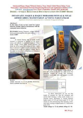
- 1. Imtaiyazul Haque, Haque Mobassir Imtiyaz, Niyaz Ahmed Abdul Mateen Khan, Veena Narayankar / International Journal of Engineering Research and Applications (IJERA) ISSN: 2248-9622 www.ijera.com Vol. 2, Issue 5, September- October 2012, pp.861-864 DIODE: - UNIQUE BEHAVIOUR DOCUMENTATION ON IN4007 DIODE IMTAIYAZUL HAQUE & HAQUE MOBASSIR IMTIYAZ & NIYAZ AHMED ABDUL MATEEN KHAN & VEENA NARAYANKAR department of electronics engineering m.h.s.s institution of engg.and technology. ABSTRACT In this study of ours we have noted few typical behavior of diode which is inconsistence with the commonly known behavior KEYWORDS: biasing, frequency, voltage follower, barrier potential,amplifier,unity gain follower DIODE IN4007 THEORY In normal biasing state of diode anode terminal is connected to positive of the power source and cathode is connected to ground. When anode voltage crosses inner barrier potential of diode the device goes into conduction state where there is increase in output current with constant Vak (voltage across anode and cathode) voltage. But in this paper we have observed the behavior of diode at different biasing conditions In this we are keeping anode voltage at 0.5v and cathode at 0v and we come across the following relation of current and resistance. Resistance is in mega ohm and current s in milli amperes. BIASING 6 ANODE VOLTAGE VA IS AT HIGHER POTENTIAL 5 va THAN CATHODE VOLTAGE VK 4 vk 3 I (in ma) 2 R(MEGA) 1 0 1 2 3 4 5 6 7 8 9 In above observation we can see that inspite of constant d.c. bias the resistance and current both forming a valley much similar to a sinusoid waves. Resistance is varying between highest peak of 5.58 and lowest peak of 1.8. the current in most pronouncing form forming a sino- soid valley varying in highest peak of 1.5 and lowest peak of 0.6. Anode voltage va = 2v & cathode voltage vk = 0v 861 | P a g e
- 2. Imtaiyazul Haque, Haque Mobassir Imtiyaz, Niyaz Ahmed Abdul Mateen Khan, Veena Narayankar / International Journal of Engineering Research and Applications (IJERA) ISSN: 2248-9622 www.ijera.com Vol. 2, Issue 5, September- October 2012, pp.861-864 3.5 0/2.9 80 60 40 3.5 0/2.9 20 0 I (in ma) R(MEGA) In the above three reading though we kept cathode voltage at zero but with increase in anode voltage the cathode voltage followed the anode voltage with a difference of 0.7 va = 2v then vk = 1.4v,va = 2.5v then vk = 1.8v, va = 3.5v then vk = 2.9v, and the resistance is constant at 4.7 m ohm,4.68 mohm and 4.68 ohm but with increase in anode voltage the current reduces in the sequence 74.3ma,74ma,73.5ma,73.3ma. it means the current and resistance behaviour in independent of their change ANODE VOLTAGE VA AND CATHODE VOLTAGE VK IS AT SAME POTENTIAL anode voltage va = 0.5v cathode voltage vk = 0.5v 2 0/1.4 90 80 80 70 60 60 va 50 vk 40 2 0/1.4 40 I (in ma) 20 30 R(MEGA) 0 20 I (in ma) R(MEGA) 10 0 Anode voltage va = 2.5v & cathode voltage vk = 1 3 5 7 9 11 13 15 0v When we are keeping anode and cathode 2.5 0/1.8 both at 0.5voltsvaries from 1.13 to high valley of 4.72 and then reduces to sinusoid nature with high 80 peak of 3 to to lowest peak of 0.05. similarly current starts from 76.7ma then sudden drop 0.9ma and the 60 sinusoidal varying with highest peak of 75.8ma and lowest peak of 73.9ma 40 2.5 0/1.8 anode voltage va = 2v cathode voltage vk = 2v 20 0 I (in ma) R(MEGA) Anode voltage va = 3.5v & cathode voltage vk = 0v 862 | P a g e
- 3. Imtaiyazul Haque, Haque Mobassir Imtiyaz, Niyaz Ahmed Abdul Mateen Khan, Veena Narayankar / International Journal of Engineering Research and Applications (IJERA) ISSN: 2248-9622 www.ijera.com Vol. 2, Issue 5, September- October 2012, pp.861-864 anode voltage va = 16v cathode voltage vk = 16v anode voltage va = 22v cathode voltage vk = 22v 180 160 140 120 When we are varying the anode and cathode from 100 3volt to 22volt the current is near about constant 80 va DIODE AS UNITY GAIN FOLLOWER OR 60 vk AMPLIFIER? 40 I (in ma) 20 R(MEGA) 0 1 5 9 13 17 21 25 When we are keeping anode and cathode both at 1volts current starts at 11.38 and sinusoidly varies from highest peak of 154.5 to lowest peak of 106, and the resistance is near about constant with slight variation anode voltage va = 3v cathode voltage vk = 3v anode voltage va = 4v cathode voltage vk = 4v diode as amplifier 863 | P a g e
- 4. Imtaiyazul Haque, Haque Mobassir Imtiyaz, Niyaz Ahmed Abdul Mateen Khan, Veena Narayankar / International Journal of Engineering Research and Applications (IJERA) ISSN: 2248-9622 www.ijera.com Vol. 2, Issue 5, September- October 2012, pp.861-864 CONCLUSION: on the basis of above observations we can say that on practical analysis diode is much more than a switch or for the matter rectyifier . we have seen the sinusoid variations of current and resistances, which is independent of each other. We have seen diode behaving as amplifier with albiet low gain.we are carrying out further studies to put the above behaviour interms of mathmetical/solid state devices equation. This may leads to complete new out look toward a conventional diode and new applicaions will come in picture diode as amplifier Diode as unity gain follower 864 | P a g e