Implementation of I2C Master Bus Protocol on FPGA

The focus of this paper is on I2C (Inter-Integrated Circuit) protocol interface between Master Bus protocol and slave. Here we are interfacing between micro-controller and DS1307. I2C bus protocol sends 8 bit data from micro-controller to DS1307. This module was designed in VHDL and simulated and synthesized using Xilinx ISE Design Suite 14.2. I2C and optimized for area and power. This concept is widely applicable from any high speed device or low speed device to any low speed device or high speed device. This module acts as a slave for the DS1307 at the same time acts like a master for the micro-controller device which can be considered as a slave. . It can be used to interface low speed peripherals like motherboard, embedded system, mobile phones, set top boxes, DVD, PDA’s or other electronic devices.

Recommended
More Related Content
What's hot
What's hot (20)
Viewers also liked
Viewers also liked (20)
Similar to Implementation of I2C Master Bus Protocol on FPGA
Similar to Implementation of I2C Master Bus Protocol on FPGA (20)
Recently uploaded
Recently uploaded (20)
Implementation of I2C Master Bus Protocol on FPGA
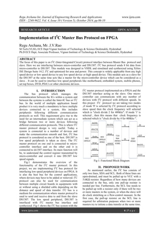
- 1. Regu Archana Int. Journal of Engineering Research and Applications www.ijera.com ISSN : 2248-9622, Vol. 4, Issue 10 ( Version 5), October 2014, pp.06-10 www.ijera.com 6 | P a g e Implementation of I2 C Master Bus Protocol on FPGA Regu Archana, Mr. J.V.Rao M.Tech (VLSI), ECE Dept Vignan Institute of Technology & Science Deshmukhi, Hyderabad Ph.D ECE Dept, Associate Professor, Vignan Institute of Technology & Science Deshmukhi, Hyderabad ABSTRACT The focus of this paper is on I2 C (Inter-Integrated Circuit) protocol interface between Master Bus protocol and slave. Here we are interfacing between micro-controller and DS1307. I2 C bus protocol sends 8 bit data from micro-controller to DS1307. This module was designed in VHDL and simulated and synthesized using Xilinx ISE Design Suite 14.2. I2 C and optimized for area and power. This concept is widely applicable from any high speed device or low speed device to any low speed device or high speed device. This module acts as a slave for the DS1307 at the same time acts like a master for the micro-controller device which can be considered as a slave. . It can be used to interface low speed peripherals like motherboard, embedded system, mobile phones, set top boxes, DVD, PDA’s or other electronic devices. I. INTRODUCTION The bus protocol which manages the communication between the ICs within a system and between the systems is called the Inter-IC bus or I2 C bus. In the world of multiple application based product it is very much a mandatory to have multiple devices connected to a system, this includes peripherals following different communication protocols as well. This requirement give rise to the need for an intermediate system which can act as a bridge between two or more devices following different communication protocols. This is where I2 C master protocol design is very useful. Today a system is connected to a number of devices and make the communication smooth and fast, I2 C bus protocol is considered as one of the best. DS1307 is low speed peripherals is taken as slave. The I2 C master protocol on one end is connected to micro- controller interface and on the other end it is connected to ds1307 interface. Its main function will be, to understand the control register transmitted by micro-controller and convert it into DS1307 low speed signals. Fig.1 demonstrates the overview of the functionality of the I2 C master protocol. In this project, we are implementing I2 C bus protocol for interfacing low speed peripheral devices on FPGA. It is also the best bus for the control applications, where devices may have to be added or removed. I2 C protocol can also be used for communication between multiple circuit boards in equipments with or without using a shielded cable depending on the distance and speed of data transfer. I2 C bus is a medium for communication where master protocol is used to send and receive data to and from the slave DS1307. The low speed peripheral, DS1307 is interfaced with I2 C master bus interface and synthesized. Fig-1 shows the I2 C bus system with the I2 C master protocol implemented on a FPGA and the DS1307 interface acting as the slave. One micro- controller can communicate with any number of devices with I2 C protocol with different speeds. In this project I2 C protocol we are taking two modes ,if mode '0' is selected by I2 C protocol according to slave speed then the clock frequency will selected which is "clock divide 2 for 400khz". If mode '1' is selected , then this means that clock frequency is selected which is "clock divide by 4 for 400khz ". Fig 1: Functional Block Diagram II. PROPOSED WORK As mentioned earlier, the I2 C bus consists of only two lines, SDA and SCL. Both of these lines are open-drained, and must be pulled up to VCC with a 5.6KΩ resistor. Regardless of how many devices are connected to the bus, only one pull-up resister is needed per line. Furthermore, the SCL line needs to be pulled up with a resistor only if there will be two or more masters in the system, or when the slave will do clock stretching as a flow-control measure. In the first case, the pull-up resistor on the SCL line is required for arbitration purposes when two or more masters try to initiate a data transfer at the same time. RESEARCH ARTICLE OPEN ACCESS
- 2. Regu Archana Int. Journal of Engineering Research and Applications www.ijera.com ISSN : 2248-9622, Vol. 4, Issue 10 ( Version 5), October 2014, pp.06-10 www.ijera.com 7 | P a g e An arbitration procedure has been defined to avoid the chaos that might ensue from such an event. In the second case, a receiver may not be ready to receive data from the transmitter, and so it will hold the SCL line low to “stretch” the clock to delay the transmitter. III. I2 C Protocol The I2 C bus is idle when both SCL and SDA are at a logic 1 level. The master initiates a data transfer by issuing a START condition, which is a high to low transition on the SDA line while the SCL line is high as shown in Figure 2 (a). The bus is considered to be busy after the START condition. After the START condition, a slave address is sent out on the bus by the master. This address is 7 bits long followed by an eighth bit which is a data direction bit (R/W) where a 0 indicates a write from the master to the slave and a 1 indicates a read from the slave to the master. The master, who is controlling the SCL line, will send out the bits on the SDA line, one bit per clock cycle of the SCL line, with the most significant bit sent out first. The value on the SDA line can be changed only when the SCL line is at a low. Fig. 2 (a) Start condition (b) Stop Condition The slave device whose address matches the address that is being sent out by the master will respond with an acknowledgment bit on the SDA line by pulling the SDA line low during the ninth clock cycle of the SCL line as shown in Figure 3. The direction bit (R/W) determines whether the master or the slave will be the transmitter in the subsequent data transmission after the sending of the slave address. Every byte put on the SDA line for transmission must be 8-bits long with the most significant bit first. Except for the START and STOP conditions, the SDA line must not changed when the SCL line is high. The number of bytes that can be transmitted is unrestricted. Each byte has to be followed by an acknowledge bit. The acknowledge- related clock pulse is generated by the master. The transmitter releases the SDA line (sets it high) during the acknowledge clock pulse, and the receiver must pull down the SDA line during the acknowledge clock pulse to acknowledge the receipt of the byte. The one exception is when a master-receiver is involved in a transfer. In this case the master-receiver must signal the end of data to the slave-transmitter by not generating an acknowledge on the last byte that was clocked out of the slave. To signal the end of data transfer, the master will send a STOP condition by pulling the SDA line from low to high while the SCL line is at a high as shown in Figure 2 (b). Instead of sending a STOP condition, the master can send a repeated START condition so that the master can change the direction of the data transmission without having to release the bus. IV. Serial Data Communication The I2 C bus has two modes of operation: master transmitter and master receiver. The I2 C master bus initiates data transfer and can drive both SDA and SCL lines. Slave device (DS1307) is addressed by the master. It can issue only data on the SDA line. In master transmission mode, after the initiation of the START sequence, the master sends out a slave address. The address byte contains the 7 bit DS1307 address, which is 1101000, followed by the direction bit (R/ w ). After receiving and decoding the address byte the device outputs acknowledge on the SDA line. After the DS1307 acknowledges the slave address + write bit, the master transmits a register address to the DS1307 this will set the register pointer on the DS1307. The master will then begin transmitting each byte of data with the DS1307 acknowledging each byte received. The master will generate a stop condition to terminate the data write. In master receiver mode, the first byte is received and handled as in the master transmission mode. However, in this mode, the direction bit will indicate that the transfer direction is reversed. Serial data is transmitted on SDA by the DS1307 while the serial clock is input on SCL. START and STOP conditions are recognized as the beginning and end of a serial transfer (Fig-5). The address byte is the first byte received after the start condition is generated by the master. The address byte contains the 7-bit DS1307 address, which is 1101000, followed by the direction bit (R/ w ). After receiving and decoding the address byte the device inputs acknowledge on the SDA line. The DS1307 then begins to transmit data starting with the register address pointed to by the register pointer. If the register pointer is not written before the initiation of a read mode, the first address that is read is the last one stored in the register pointer. The DS1307 must receive a “not acknowledged” to end a read.
- 3. Regu Archana Int. Journal of Engineering Research and Applications www.ijera.com ISSN : 2248-9622, Vol. 4, Issue 10 ( Version 5), October 2014, pp.06-10 www.ijera.com 8 | P a g e Fig. 5 - Master Receiver Mode Fig. 6: Acknowledgement on the I2 C Bus MAXIM DS1307: The DS1307 supports a bi-directional, 2- wire bus and data transmission protocol. The pin assignment of DS1307 is given in Fig-6. The DS1307 operates as a slave on the 2- wire bus. Fig-7 shows the interface connection of I2 C bus in Spartan 3E with the DS1307 RTC chip. Fig. 7: DS1307 connected to two wire data bus V. SOFTWARE IMPLEMENTATION I2 C master protocol is designed using VHDL based on Finite State Machine (FSM). FSM is a sequential circuit that uses a finite number of states to keep track of its history of operations, and based on history of operation and current input, determines the next state. There are several states in obtaining the result. Algorithm State 1: An idle condition: I2 C bus doesn’t perform any operation. (SCL and SDA remains high). State 2: Start condition: master initiates data transmission by providing START (SCL is high and SDA is from high to low). State 3: Slave address - write: master sends the slave address-write (11010000) to the slave. State 4: If the slave address matches with the slave, it sends an acknowledgement bit in response to the master. State 5: 8 Bit Register Address[12] will be transmitted to the slave. Again acknowledgement is sent to the master by the slave. State 6: Data to be transmitted is sent to the slave by the master. After receiving the data, slave acknowledges the master. State 7: Stop condition: Slave sends a stop bit to the master to terminate the communication (SCL is high and SDA is from Low to high). For performing read operation, write operation is performed first and then read operation is done. Slave address for read is 11010001. (State 7 will not be performed for read operation) State 8: Master transmits slave address for read operation to the slave. State 9: Master receives the data from the slave and acknowledges the slave. State 10: Master sends a STOP bit to terminate the connection (SCL is high and SDA is from Low to high). Fig.8 shows the flowchart for I2 C master bus communication with slave device. Fig-10 shows the simulation result for DS1307. In DS1307, we have activated only 4th order FIR filter for the given data input and filter coefficients are applied and output is observed. Generated square output is also observed programmed in VHDL. Fig-11 shows the simulation
- 4. Regu Archana Int. Journal of Engineering Research and Applications www.ijera.com ISSN : 2248-9622, Vol. 4, Issue 10 ( Version 5), October 2014, pp.06-10 www.ijera.com 9 | P a g e result for I2 C, a dataout, sda, read and write operations are observed in the I2 C Master. To read the written data from the slave, the write operation takes place first followed by the repeated start condition and sending the slave address read (11010001) in each state of FSM. Fig. 8: Flowchart for I2 C master bus communication with slave device VI. Results & Discussion Here the I2 C bus protocol is designed using VHDL and implemented in Spartan 3E using Xilinx ISE Design Suite14.2. The simulation results are shown below: Fig. 9: Schematic Diagram of I2 C Master Bus The below table shows the Xilinx Device Utilization Summary. The result shows that minimal resources are utilized in designing the I2 C master as only 2% slices, 1% flip flops and 1% LUTs are utilized. Device Utilization Summary (estimated values) In DS1307, we have activated only 4th order FIR filter and chosen the below values pertaining to the filter. Input Signal: x0, x1, x2, x3 = '2'; Filter Coefficients: h0=1, h1=2, h2=4, h3=5. Data Output (y) = x(0).h(3) + x(1).h(2) + x(2).h(1) + x(3).h(0) We obtained the output dataoutput(y) = 24 after 4 taps, square wave is generated at sqt_out. Fig. 10: Simulation of DS1307 Fig. 11: Simulation of I2 C master VII. CONCLUSION The result shows that minimal resources are utilized in Spartan 3E. The design process is simplified using VHDL to design the I2 C bus
- 5. Regu Archana Int. Journal of Engineering Research and Applications www.ijera.com ISSN : 2248-9622, Vol. 4, Issue 10 ( Version 5), October 2014, pp.06-10 www.ijera.com 10 | P a g e protocol, I2 C Master (Master) transmits and receives data to and from the DS1307 (Slave). So that any low speed peripheral devices can be interfaced using I2 C bus protocol as master. In future, this can be implemented as real time clock in networks that contains multiple masters and multiple slaves to coordinate the entire system by clock synchronization techniques. REFERENCES [1] I2 C Bus Specification, Philips Semiconductor, version 2.1, January 2000. [2] DS1307 64 x 8, Serial, I2 C Real Time Clock, Maxim integrated, 2008. [3] Prof. Jai Karan Singh et al “Design and Implementation of I2 C master controller on FPGA using VHDL,” IJET, Aug-Sep 2012. [4] Raj Kamal, “Devices and Communication Buses for Devices Network,” in Embedded system: Architecture programming and Design, Shalini Jha Ed. New Delhi, India: Tata McGraw-Hill Education, 2008, pp.160- 165. [5] Tim Wilmshurst, “Starting with Serial,” in Designing Embedded [6] Spartan-3A/3AN FPGA Starter Kit Board User Guide, Xilinx, version 1.1, 2008. [7] A.P.Godse, D.A.Godse, “Bus Standards,” in Microprocessors and its Applications, 3rd Ed. Pune, India: Technical publications, 2008. [8] Systems with PIC Micro-controllers: Principles and Applications, 2nd Ed. Burlinton: Newnes, 2009, pp.307-327. [9] Vincent Himpe, “Historical background of I2 C,” in Mastering the I2 C Bus, Aachen, Germany: Elektor Verlag publications, 2011. [10] Pong P.Chu, “I/O Modules,” in FPGA Prototyping by Verilog Examples: Xilinx Spartan – 3 Version, New Delhi, India: Wiley, 2008.