Navigating the Deluge_ Dubai Floods and the Resilience of Dubai International...
Engr gidado structural design updated1
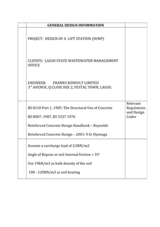
1. GENERAL DESIGN INFORMATION
PROJECT: DESIGN OF A LIFT STATION (SUMP)
CLIENTS: LAGOS STATE WASTEWATER MANAGEMENT
OFFICE
ENGINEER: FRAMES KONSULT LIMITED
3rd
AVENUE, Q CLOSE HSE 2, FESTAC TOWN, LAGOS.
BS 8110 Part 1, 1985: The Structural Use of Concrete
BS 8007: 1987, BS 5337 1976
Reinforced Concrete Design Handbook – Reynolds
Reinforced Concrete Design – 2001: V.O. Oyenuga
Relevant
Regulations
and Design
Codes
Assume a surcharge load of 2.0KN/m2
Angle of Repose or soil Internal friction = 35°
Use 19kN/m3 as bulk density of the soil
100 - 120KN/m3 as soil bearing
2. Severe
Exposure
Condition
Characteristic strength of concrete = 30N/mm2
Characteristic strength of Main bars fy = 460N/mm2
Characteristic strength of links = 250N/mm2
Material
Data
REFER
ENCE
DESCRIPTIONS Output
(I)
(ii)
(iii)
(iv)
(v)
LOADING CONDITIONS
Empty Sump
Pressure on walls resulting from backfill earth material
Pressure of groundwater
Surcharge pressure due to imposed load
Pressure due to retain liquid sump dimension as given 2.5
x 2.5 x 4m
Assumption
Wall thickness = 300mm
Depth of soil H20 from ground level = 1000mm
Free Board = 300mm
DEDUCTIONS
Height of Active Earth Pressure = 4.0 + 0.3 = 4.3m
Height of pore water pressure = 4.0 - 1.0 + 0.3 = 3.3m
Height of retained wastewater = 4 – 0.3 = 3.7m
Assume a surcharge load of 2.0KN/m2
Given that :
Ps = Ka x surcharge load
But Ka = tan2
(45 – Ø/2)
Where Ø = angle of repose or soil internal friction, assume
35ο
: Ka = tan2
(45 -35/2)
= 0.2709≈0.271
Hence, Ps (surcharge pressure) = 0.271 x 2.0
= 0.542KN/m2
Pb (Active Earth Pressure – Bulk Soil)
= 0.271 x 19 x 1.0 = 5.149
Psm = (Active Earth Pressure – Submerged Soil)
= 0.271 x (19 – 10) x 3.3
= 8.049KN/m2
Pw = ( Active Wastewater Pressure) = 12 x 3.7
= 44.4KN/m= 44.4KN/m2
These value can be represented in the pressure diagramThese value can be represented in the pressure diagram
below:
PRESSURE DIAGRAM
2
(3) (4)
400m C
300
300
300 A
300 500 A 300
500
B 300 AB 300 A
2.5
2.5
3. Weight of water to be displaced
= Area of base x height of water H20 x unit weight of water
H20
= 3.1 x 3.1 x3.7 x 10
= 355.6KN
Volume of concrete in tank using 300mm thick concrete.
( 3.1 x 0.3 x 4) 2 ( front and back)
( 2.5 x 0.3 x 4) 2 ( sides)
3.1 x 3.1 x 0.3 (base)
3.1 x 3.1 x 0.2 ( cover)
7.44 + 6.0 + 2.883 +1.922 = 18.245m3
Weight of lift station = 18.245 x 24
= 437.88
: weight of lift station = 437.88
Weight of water 355.6 = 1.232
The lift station cannot be floated, hence O.K
LOADING
Sump load = 437.88KN @ SLS ≈ 438KN
Water load = 2.5 x 2.5 x 3.7
23.125 @ SLS ≈ 23KN
Loading at ULS
4. 439 x 1.4 + 23 x 1.6
= 650N
Assuming even distribution over the base; udl of:
650 = 67.74
3.1 x 3.1 ≈ 67.74KN/m2
Maximum Moment Mmax = Wlx2
8
= 0.125Wlx2
= 0.125 x 67.74 x 2.52
= 52.92KNm
Adopt same reinforcement as for the walls.
Provide Y25 @ 150c
/c Bottom and Top.
Provide similar U bars @ corners.
.