Downloaded 2,444 times
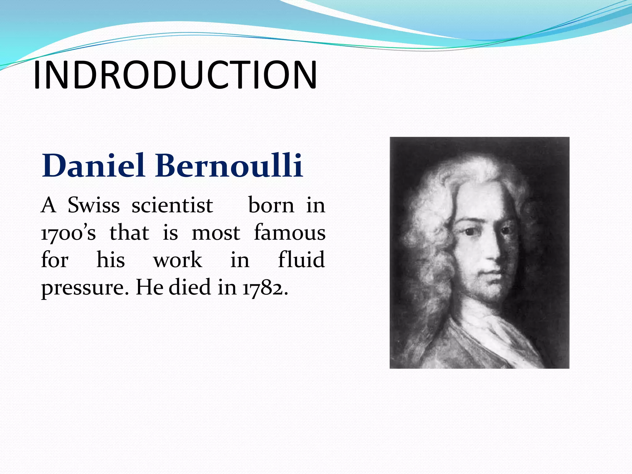
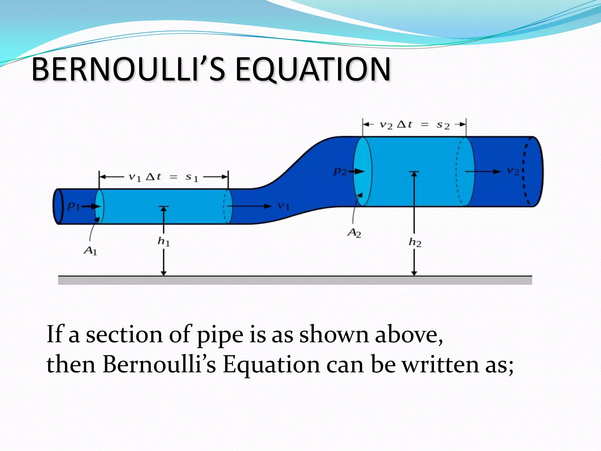

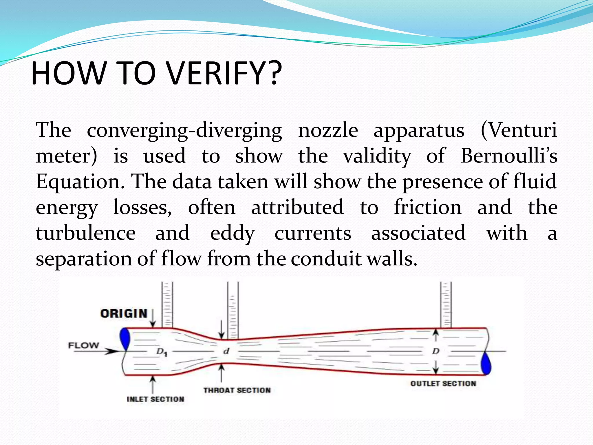
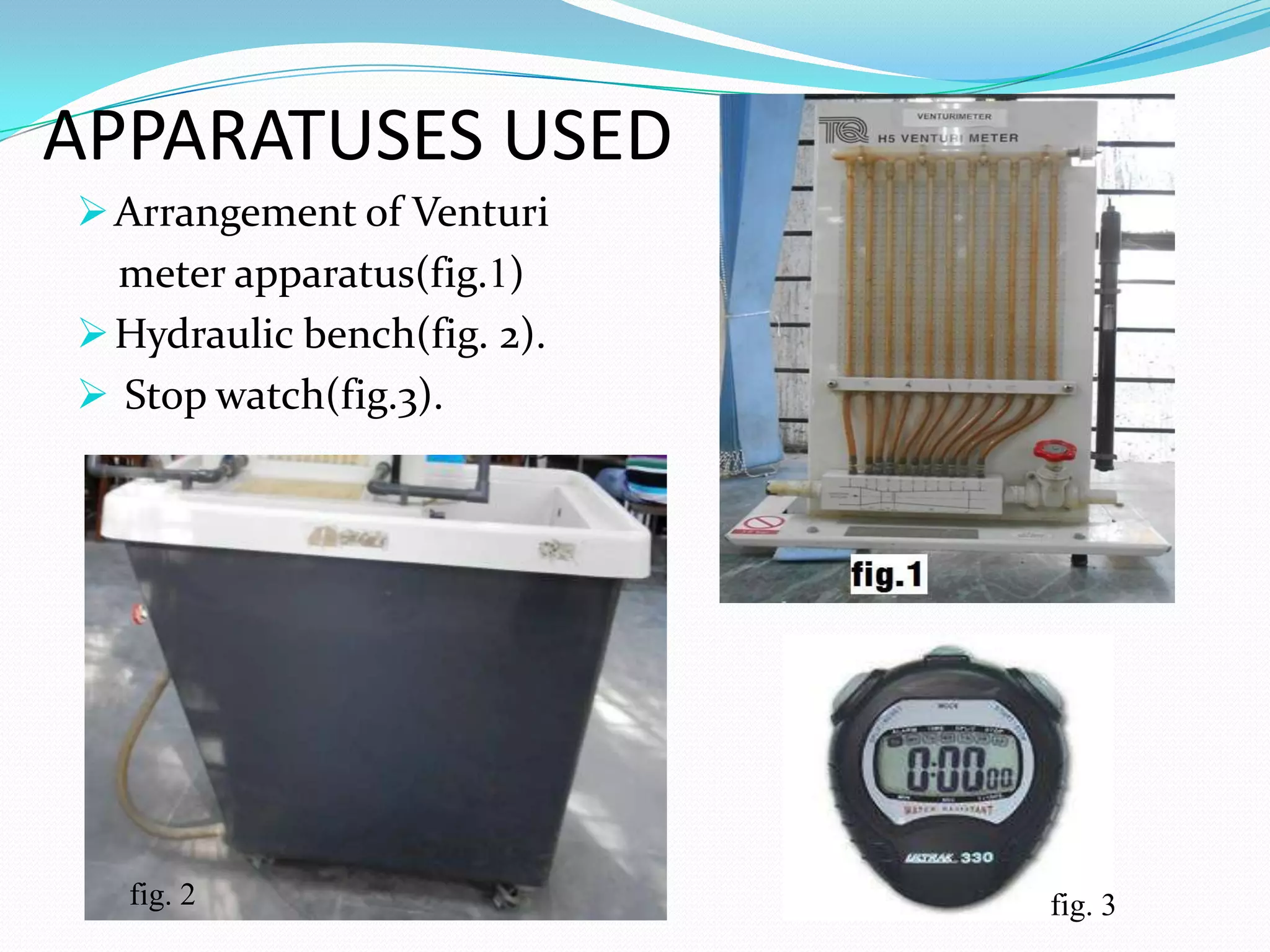
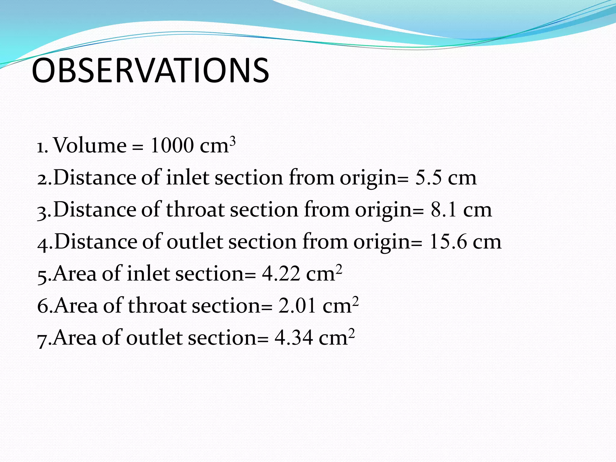
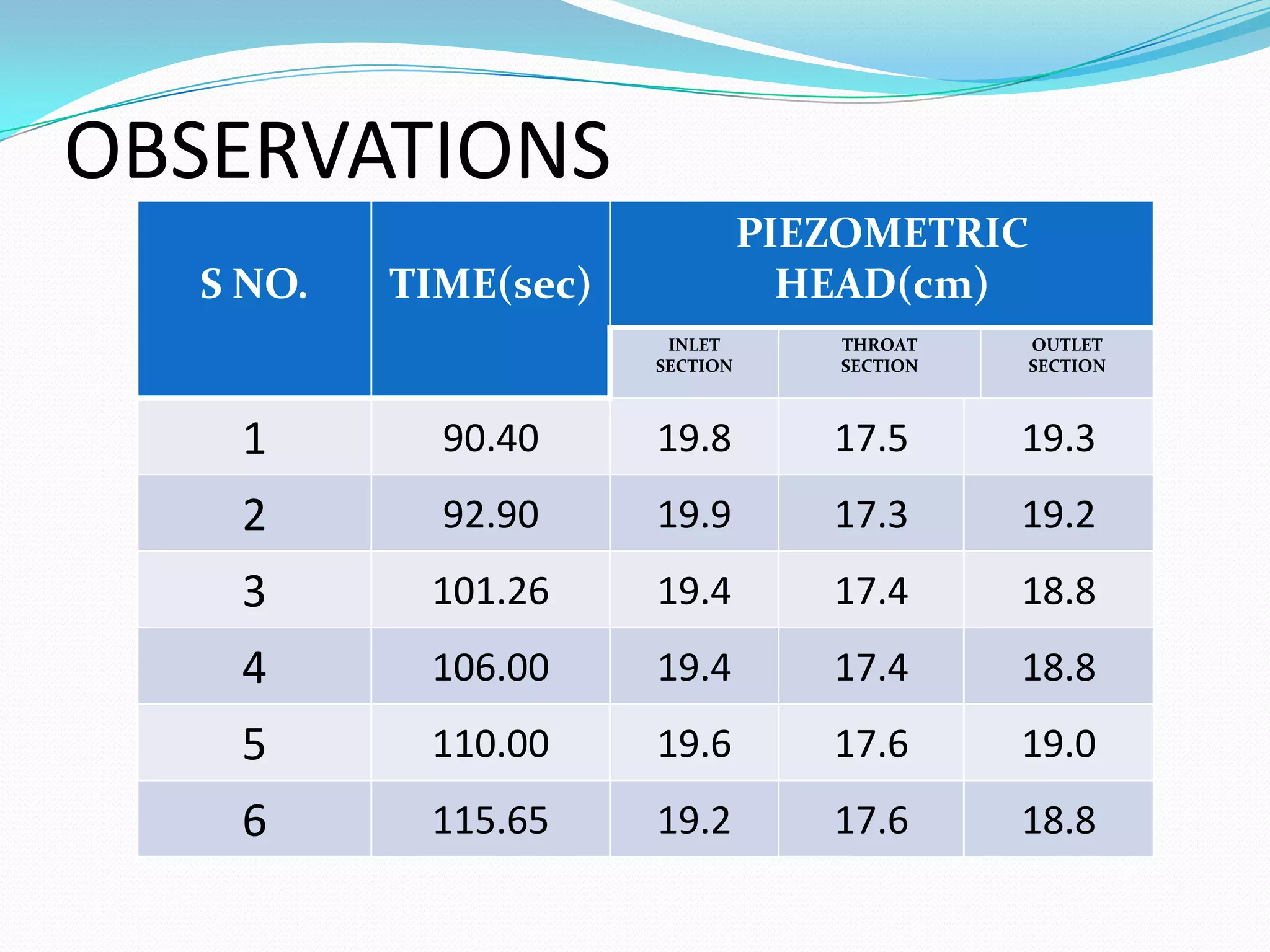
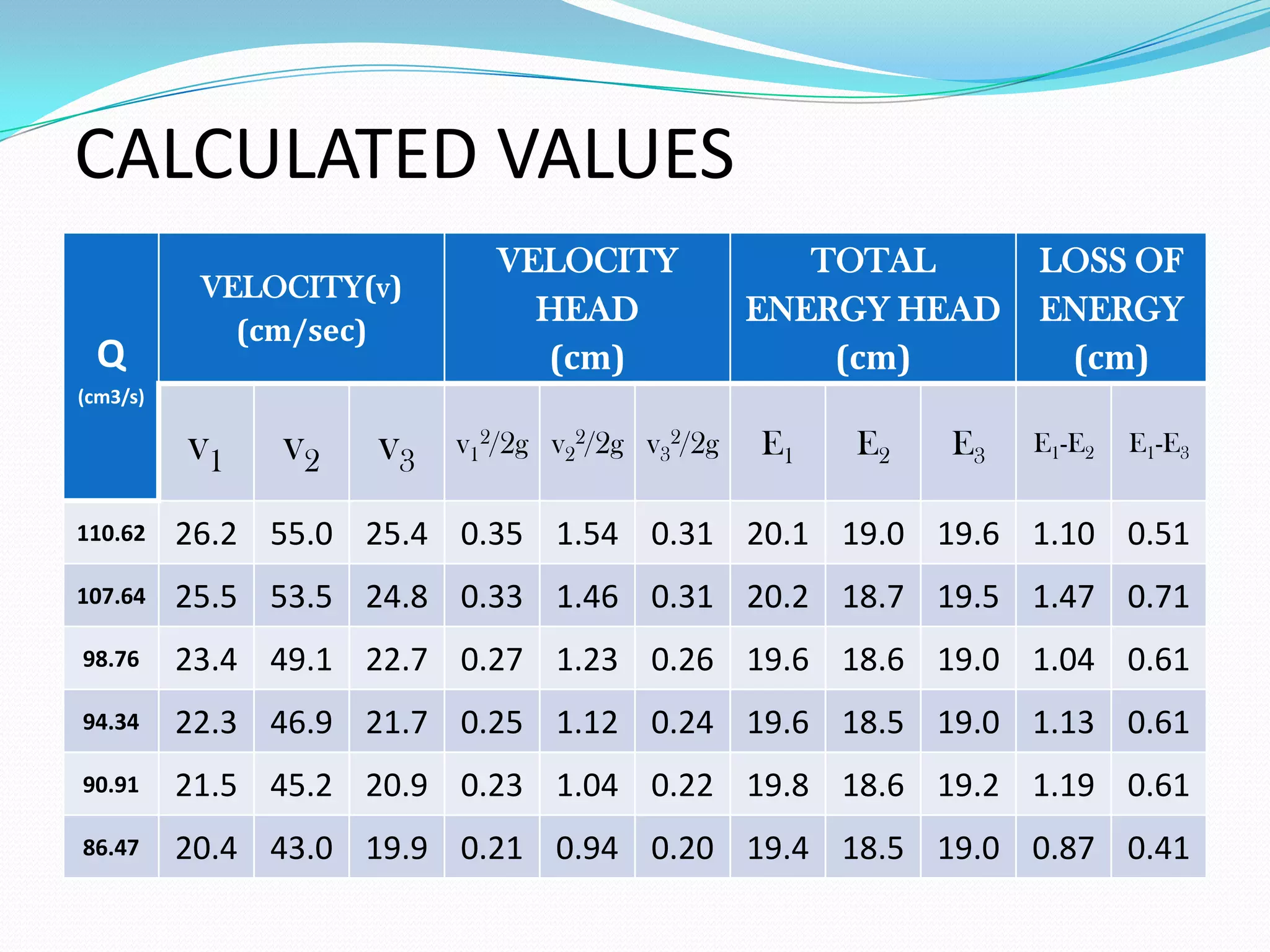
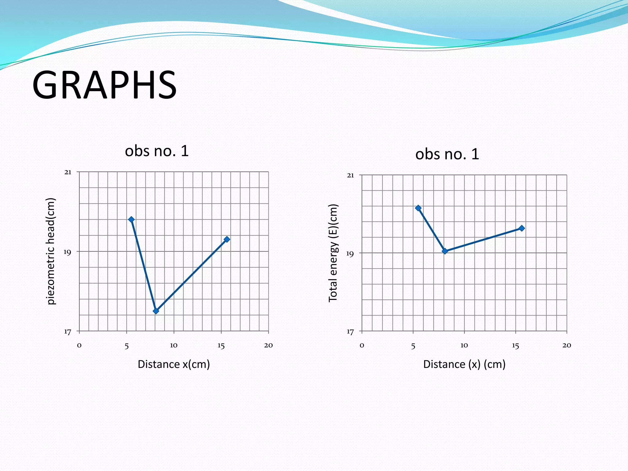
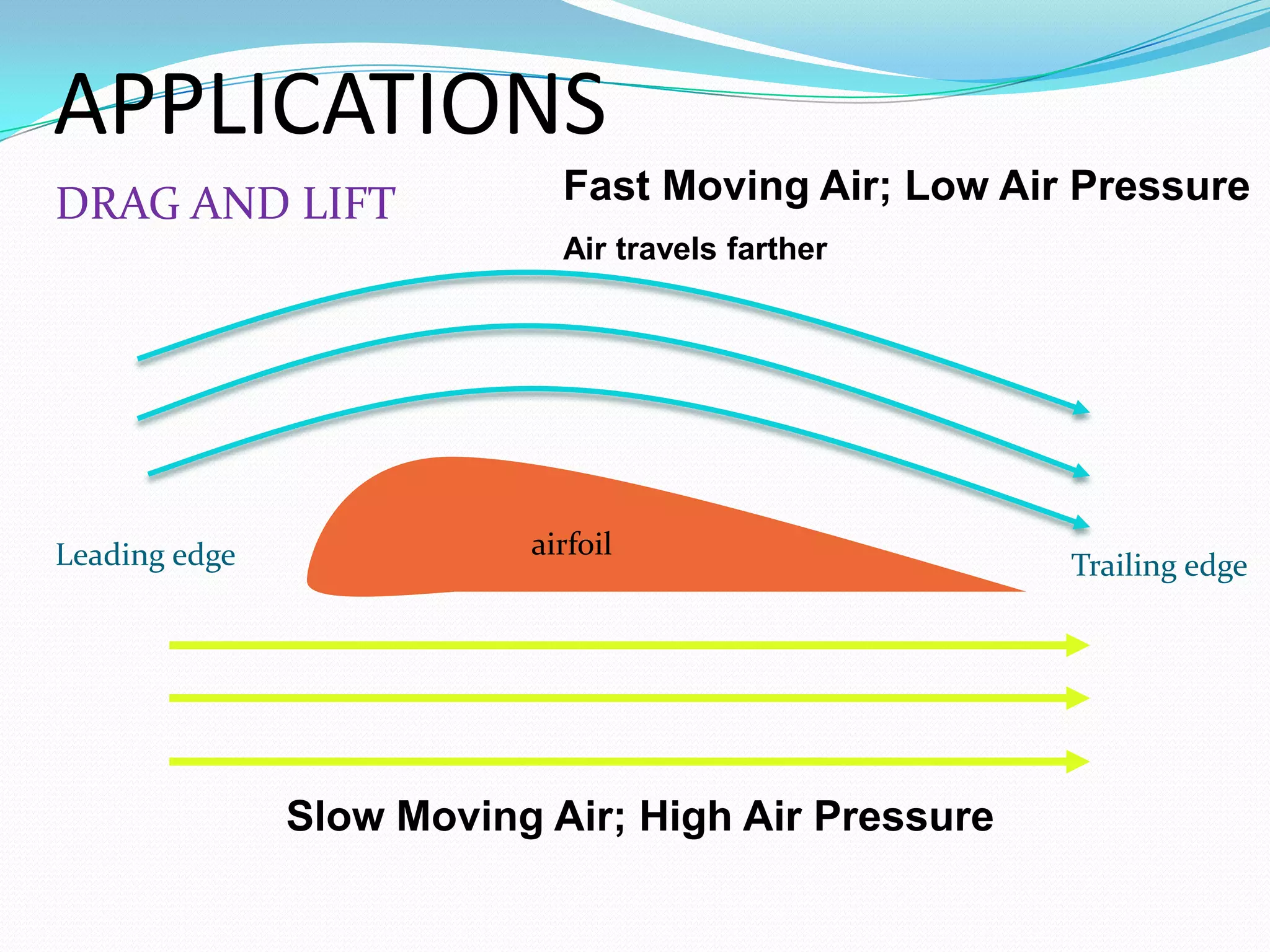
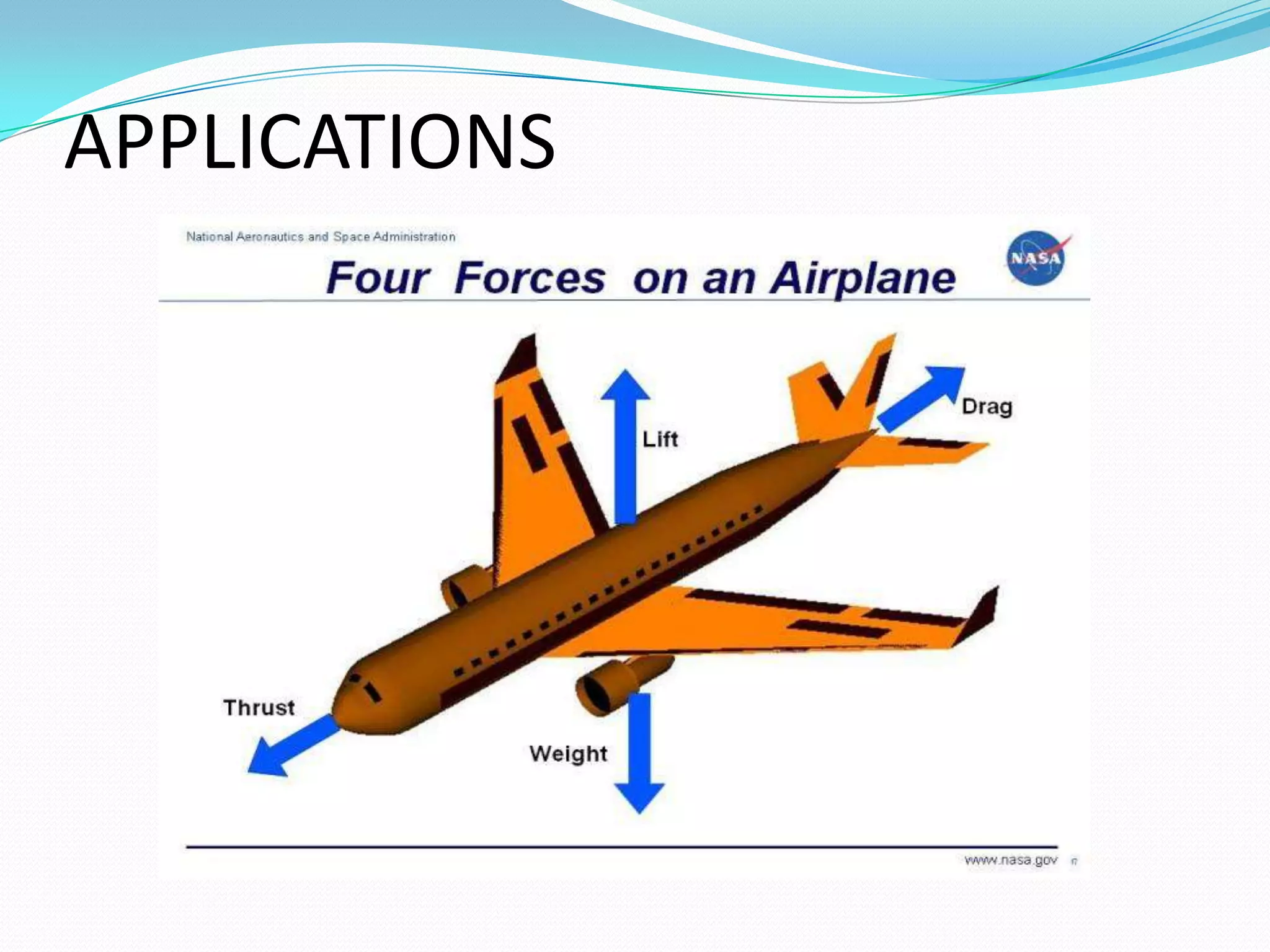


This document summarizes Daniel Bernoulli and his theorem on fluid mechanics. It discusses how Bernoulli, a Swiss scientist born in the 1700s, discovered that an increase in the speed of a moving fluid is accompanied by a decrease in the fluid's pressure. Bernoulli's principle, also called Bernoulli's theorem, states that the total energy in a fluid remains constant provided the flow is steady, frictionless, and incompressible. The document then provides Bernoulli's equation and describes experiments using a Venturi meter to verify the theorem by measuring pressure and velocity changes at different pipe sections. It concludes that the experiments validate Bernoulli's equation and its applications in fluid mechanics and aerodynamics.