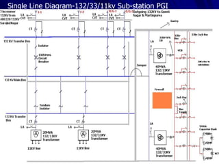
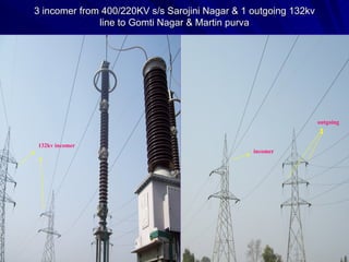
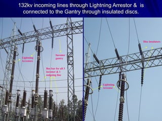
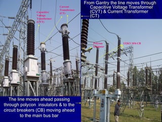
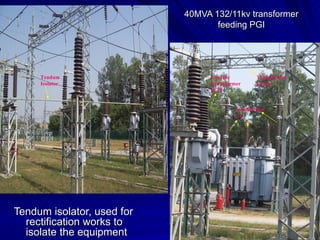
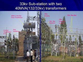
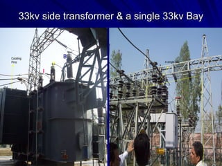
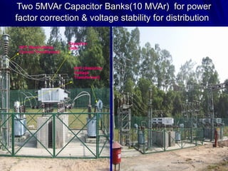
A visit to 132kv S/S PGI
Single Line Diagram-132/33/11kv Sub-station PGI
3 incomer from 400/220KV s/s Sarojini Nagar & 1 outgoing 132kv line to Gomti Nagar & Martin purva 132kv incomer incomer outgoing
132kv incoming lines through Lightning Arrestor &  is connected to the Gantry through insulated discs. Disc insulators Lightning Arrestor Incomer gantry Lightning Arrestors Bus bar for all 3 incomer & 1 outgoing line
The line moves ahead passing through polycon  insulators & to the circuit breakers (CB) moving ahead to the main bus bar From Gantry the line moves through Capacitive Voltage Transformer (CVT) & Current Transformer (CT)  Capacitive Voltage Transformer(CVT) Current Transformer(CT) Polycon Insulator 132KV SF6 CB
The line ,through the isolators is distributed in the s/s through Main bus. Main Bus bar 132kv Bay
132kv Bay terminating to 20MVA 132/11kv Transformer Isolators Transfer Bus
40MVA 132/11kv transformer feeding PGI Tendum isolator, used for rectification works to isolate the equipment Transformer Gantry Transformer LA Current Transformer(CT) Tendum Isolator
33kv Sub-station with two 40MVA(132/33kv) transformers 40MVA 132/33kv Emco Transformer Post insulators Current Transformer(CT) 33kv Bus Bar 33kv GAntry 33kv  Disc Insulators 33kv Gantries  (1 & 2)
33kv side transformer & a single 33kv Bay Oil Tank Cooling Fans A single bay R Y B Cooling Fins
Jack Bus, used for the purpose of isolation of a bay for rectification
Two 5MVAr Capacitor Banks(10 MVAr)  for power factor correction & voltage stability for distribution NCT (Neutralising Current Transformer) RVT (Resistive Voltage Transformer) Capacitor Cells
THANKING YOU Chanmeet Singh Syal & Swapnil Srivastava.

132kv Substation

  • 1.
    A visit to132kv S/S PGI
  • 2.
  • 3.
    3 incomer from400/220KV s/s Sarojini Nagar & 1 outgoing 132kv line to Gomti Nagar & Martin purva 132kv incomer incomer outgoing
  • 4.
    132kv incoming linesthrough Lightning Arrestor & is connected to the Gantry through insulated discs. Disc insulators Lightning Arrestor Incomer gantry Lightning Arrestors Bus bar for all 3 incomer & 1 outgoing line
  • 5.
    The line movesahead passing through polycon insulators & to the circuit breakers (CB) moving ahead to the main bus bar From Gantry the line moves through Capacitive Voltage Transformer (CVT) & Current Transformer (CT) Capacitive Voltage Transformer(CVT) Current Transformer(CT) Polycon Insulator 132KV SF6 CB
  • 6.
    The line ,throughthe isolators is distributed in the s/s through Main bus. Main Bus bar 132kv Bay
  • 7.
    132kv Bay terminatingto 20MVA 132/11kv Transformer Isolators Transfer Bus
  • 8.
    40MVA 132/11kv transformerfeeding PGI Tendum isolator, used for rectification works to isolate the equipment Transformer Gantry Transformer LA Current Transformer(CT) Tendum Isolator
  • 9.
    33kv Sub-station withtwo 40MVA(132/33kv) transformers 40MVA 132/33kv Emco Transformer Post insulators Current Transformer(CT) 33kv Bus Bar 33kv GAntry 33kv Disc Insulators 33kv Gantries (1 & 2)
  • 10.
    33kv side transformer& a single 33kv Bay Oil Tank Cooling Fans A single bay R Y B Cooling Fins
  • 11.
    Jack Bus, usedfor the purpose of isolation of a bay for rectification
  • 12.
    Two 5MVAr CapacitorBanks(10 MVAr) for power factor correction & voltage stability for distribution NCT (Neutralising Current Transformer) RVT (Resistive Voltage Transformer) Capacitor Cells
  • 13.
    THANKING YOU ChanmeetSingh Syal & Swapnil Srivastava.