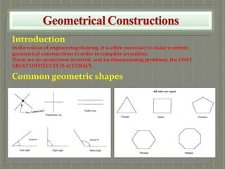
SlideShare a Scribd company logo
1 of 16
Introduction
In the course of engineering drawing, it is often necessary to make a certain
geometrical constructions in order to complete an outline.
There are no projections involved, and no dimensioning problems, the ONLY
GREAT DIFFICULTY IS ACCURACY.
Common geometric shapes
PRELIMINARY TECHNIQUES
Geometrical Construction Techniques
LINES
A POINT has noarea,
it indicatesa position,
itcan be indicated bya
dotor thus
A LINE has length but
no area. It may be
curved orstraight.
A STRAIGHT LINE is
the shortest distance
between two points.
GEOMETRICAL TERMS
BISECTING/PERPENDICULARS/PARALLELS/DIVISION
1) BISECT A LINE 2) BISECT AN ACUTE ANGLE
1. Set an acute angle (angle less than
90:), and bisect the angle.
3) BISECT OF A GIVEN ARC
1. With a compass opened to a
distancegreater than half AB, strike
arcs from A and B.
2. A line joining the points of
intersection of the arcs is the
bisector.
1. With centre A and radius greater
thanhalf AB, describe an arc.
2. Repeat with the same radius from B,
the arcs intersecting at C and D. Join
C to D to bisect the arc AB.
4) PERPENDICULAR AT A POINT ON A 5) PARALLEL LINE TO A LINE WITH A
GIVEN DISTANCE.
AB is the given line, C is the given distance.
1. From any two points well apart on
AB, draw two arcs of radius equal to
C.
2. Draw a line tangentialto the two
arcs to give required line.
6) DIVISION OF A LINE INTO EQUAL
PARTS
AB is the given line.
1. Drawa line AC at any angle.
2. On line AC, make three convenient
equal divisions.
3. Join the last division with B and draw
parallel lines as shown.
LINE
1. At point O, draw a semicircle of any
radiusto touch the line at a and b.
2. With compass at a greaterradius,
strike arcs from a and b.
CONSTRUCTIONS OF ANGLES
TERMINOLOGY
If two lines are pivoted
as sh
. own in the
diagram, as one line
opens they form an
angle. If the rotation is
continued the line will
cover a full circle. The
unit for measuring an
angle is a
NAMES OF ANGLES
7) CONSTRUCTION OF A 60° AND 30° ANGLES
8) CONSTRUCTION OF A 45° AND 90° ANGLES
CONSTRUCTION OF TRIANGLES
TERMINOLOGY
A triangle is a plane figure
bounded by three straight
lines.
Triangles are named according
to the length of their sides or
the magnitude of their angles.
EQUILATERAL
All angles 60°.
All sides equal.
ISOSCELES
Base angles equal.
Opposite sides equal
RIGHT ANGLE
One angle is 90°.
All sides of different length.
OBTUSE ANGLE
One angle is greater than 90°. All sides of
differentlength.
SCALENE
All angles different. All sides of
differentlength.
CONSTRUCTION OF TRIANGLES
9) TO CONSTRUCT AN EQUILATERAL TRIANGLE 10) TO CONSTRUCT AN ISOSCELES TRIANGLE, GIVEN
BASE AND VERTICAL HEIGHT
1.Draw a line AB, equal to the length of the side.
2.With compass point on A and radius AB, draw an
arc as shown above.
1.Drawline AB.
2.Bisect AB and mark the vertical height.
ABC is the required isosceles triangle.
11) TO CONSTRUCT A RIGHT-ANGLE TRIANGLE
1.Draw AB. From A construct angle CAB.
2.Bisect AB. Produce the bisection to cut AC at O.
3.With centre O and radius OA, draw semi-circle to
find C.
Completethe triangle
12) TO CONSTRUCT A TRIANGLE, GIVEN THE BASE
ANGLES & THE ALTITUDE
1.Draw a line AB. Construct CD parallel to AB so that the
distance between them is equal to the latitude.
2.From any point E, on CD, draw CÊF & DÊG so that they cut
AB in F & G respectively.
3.Since CÊF = EFG & DÊG = EĜF (alternateangles), then
EFG is the requiredtriangle.
THE CIRCLE
PARTS OF A CIRCLE
13) TO FIND THE CENTRE OF A
GIVEN ARC
14) TO FIND THE CENTRE OF
CIRCLES (METHOD 1)
15) TO FIND THE CENTRE OF
CIRCLES (METHOD 2)
1. Draw two chords, AC and BD.
2. Bisect AC and BD as shown. The
bisectors will intersect at E.
3. The centre of the arc is point E.
1. Draw two horizontal lines facing one
another across the circle at a place
approximately halfway from the top to
the centre of the circle. These lines pass
through the circle form points A, B, C
and D.
2. Bisect these two lines. Where these two
bisect lines intersect, thus the centre of
the given circle.
1. Draw a horizontal line across the
circle at a place approx. halfway from
the top to the centre of the circle.
2. Draw perpendicular lines downward
from A and B. Where these lines cross
the circle forms C & D.
3. Draw a line from C to B and from A to
D. Where these lines cross is the exact
centreof the given circle.
QUADRILATERALS
TERMINOLOGY
The quadrilateral is a plane figure bounded by four straight sides
SQUARE
All four sides equal.
All angles 90:.
RECTANGLE
Opposite sides of
equal.
All angle90:.
RHOMBUS
All four sides equal.
Opposite angles
equal.
PARALLELOGRAM
Opposite sides
equal.
Opposite angles
equal.
TRAPEZIUM
Two parallel
sides.
Two pairs of
angles equal.
16) TO CONSTRUCT A SQUARE
1.Draw the side AB. From B erect
a perpendicular. Mark off the
length of side BC.
2.With centres A & C draw arcs,
radius equal to the length of the
side of the square, to intersect at
D.
ABCD is the required square.
17) TO CONSTRUCT A
PARALLELOGRAM
1.Draw AD equal to the length of one of
the sides. From A construct the known
angle. Mark off AB equal length to
other known side.
2.With compass pt. at B draw an arc
equal radius to AD. With compass pt. at
D draw an arc equal in radius to AB.
ABCD is the required parallelogram.
18) TO CONSTRUCT A RHOMBUS
1.Drawthe diagonalAC.
2.From A and C draw intersecting
arcs, equal in length to the sides, to
meet at B and D.
ABCD is the required rhombus.
REGULARPOLYGONS
TERMINOLOGY
A polygon is a plane figure bounded by more than four straight sides. Regular polygons are named according to the number of their
sides.
PENTAGON
sides
:5 sides HEPTAGON :7 sides NONAGON :9 sides UNDECAGON :11
HEXAGON
sides
:6 sides OCTAGON :8 sides DECAGON :10 sides DODECAGON :12
The regular polygons drawn on this page are the figures most frequently used in geometrical drawing. Particularly the hexagon and the
octagon which can be constructed by using60⁰ or 45⁰ set-square.
REGULAR PENTAGON
Five sides equal.
Five angles equal.
REGULAR HEXAGON
Six sides equal.
Six angles equal.
REGULAR OCTAGON
Eight sides equal.
Eight angles are equal.
IRREGULAR PENTAGON RE-ENTRANT HEXAGON IRREGULAR HEPTAGON
Five sides unequal.
Five angles unequal.
One interior anglegreater than
180:.
Six sides & six angles unequal.
Seven sides unequal.
Seven angles unequal.
19) TO CONSTRUCT A
HEXAGON, GIVEN THE
DISTANCE ACROSS THE
CORNERS (A/C)
20) TO CONSTRUCT A HEXAGON,
GIVEN THE DISTANCE ACROSS THE
FLATS (A/F)
21) TO CONSTRUCT AN
OCTAGON, GIVEN THE DISTANCE
ACROSS CORNERS (A/C)
1.Drawa vertical and horizontal
centre lines and a circle with a
diameter equal to the given
distance.
2.Step off the radius around the
circle to give six equally spaced
points, and join the points to give
the required hexagon.
1.Draw vertical and horizontal centre
lines and a circle with a diameter equal
to the given distance.
Use a 60: set-square and tee-square as
shown to give the six sides.
1.Draw vertical and horizontal
centre lines and a circle with a
diameter equal to the given
distance.
2.With a 45: set-square, draw
points on the circumference 45:
apart.
Connect these eight points by
straightlines to give the required
octagon.
22) TO CONSTRUCT AN
OCTAGON, GIVEN THE
DISTANCE ACROSS CORNERS (A/C)
1.Draw vertical and horizontal centre lines and a circle with a
diameterequal to the given distance.
2.With a 45: set-square, draw points on the circumference 45:
apart.
3.Connect these eight points by straight lines to give the
requiredoctagon.
23)TO CONSTRUCT AN OCTAGON,
GIVEN THE DISTANCE
ACROSS THE FLATS (A/F
1.vertical and horizontal centre lines and a circle with
a diameter equal to the given distance.
2.Use a 45: set-square and tee-square as shown in
construction of hexagon A/F to give the eight sides.
24) TO INSCRIBE ANY REGULAR POLYGON WITHIN A CIRCLE.
e.g. PENTAGON
T
ANGENTS TO CIRCLES
TERMINOLOGY
If a disc stands on its edge on a flat surface it will touch the surface at one point. This point is known as the point of
tangency as shown in the diagram and the straight line which represents the flat plane is known as a tangent. A line
drawn from the point of tangency to the centre of the disc is called normal, and the tangent makes an angle of 90° with
the normal.
25) EXTERNAL TANGENT TO TWO CIRCLES OF
DIFFERENT Ø (OPEN BELT)
1. Join the centres of circles a and b. Bisect ab to obtain the
centre c of the semicircle.
2. From the outside of the larger circle, subtract the radius
r of the smaller circle. Draw the arc of radius ad. Draw
normal Na.
3. Normal Nb is drawn parallel to normal Na. Draw the
tangent.
26) INTERNAL TANGENT TO TWO CIRCLES OF
DIFFERENT Ø (CROSS BELT)
1. Join the centres of circles a and b. Bisect ab to obtain the
centre c of the semicircle.
2. From the outside of the larger circle, add the radius r of the
smaller circle. Draw the arc of radius ad. Draw normal Na.
3. Normal Nb is drawn parallel to normal Na. Draw the
tangent.
JOINING OF CIRCLES
27) OUTSIDE RADIUS
Two circles of radii a and b are tangentialto arc of
radiusR.
1. From the centre of circle radius a, describe an arc of R +
a.
2. From the centre of circle radius b, describe an arc of R +
b.
3. At the intersection of the two arcs, draw arc radius R.
28) INSIDE RADIUS
Two circles of radii a and b are tangential to arc of radius
R.
1. From the centre of circle radius a, describe an arc of R - a.
2. From the centre of circle radius b, describe an arc of R - b.
3. At the intersection of the two arcs, draw arc radius R.
THE ELLIPSE
TERMINOLOGY
29) CONCENTRIC/AUXILIARY CIRCLE METHOD
1.Draw two circles aroundthe major and minor axis.
2.Divide into twelve equal parts using 30: - 60: set-square.
3.Draw horizontal lines from the minor circle and vertical lines from the major circle.
4.The intersection points between horizontal and vertical lines are points of an ellipse.
AN INVOLUTE
TERMINOLOGY
There are several definitions for the involutes, none being particularly easy to follow. An involute is the path of a point
on a string as the string unwinds from a line, polygon, or circle. And it is also the locus of a point, initially on a base circle,
which moves so that its straight line distance, along a tangent to the circle, to the tangential point of contact, is equal to
the distance along the arc of the circle from the initial point to the instant point of tangency.
The involute is best visualized as the path traced out by the end of a piece of cotton when cotton is unrolled from its reel.
30) TO DRAW AN INVOLUTE OF A CIRCLE
Let the diameter of the circle is given
1. Divide the circle into 12 equal parts.
2.Draw tangents at each of the twelve
circumferential divisions point, setting off along each
tangentthe length of the corresponding circular arc.
3.Draw the required curve through the points set off
and can be determined by setting off equal distances 0-1,
1-2, 2-3, and so on, along the circumference.
NOTE:
The involutes of a circle are used in the construction of involutes gear teeth. In this system, the involutes form the face and a part
of the flank of the teeth of gear wheels; the outlines of the teeth of racks are straight lines.

More Related Content

Similar to geometricalconstruction-101112193228-phpapp01.pptx

Engineering Graphics - 1.ppt
Engineering Graphics - 1.pptEngineering Graphics - 1.ppt
Engineering Graphics - 1.ppt
SudhakarNakka3
 
Engg engg academia_commonsubjects_drawingunit-i
Engg engg academia_commonsubjects_drawingunit-iEngg engg academia_commonsubjects_drawingunit-i
Engg engg academia_commonsubjects_drawingunit-i
Krishna Gali
 
circles-131126094958-phpapp01.pdf
circles-131126094958-phpapp01.pdfcircles-131126094958-phpapp01.pdf
circles-131126094958-phpapp01.pdf
kdbdhawan
 
Conics Sections and its Applications.pptx
Conics Sections and its Applications.pptxConics Sections and its Applications.pptx
Conics Sections and its Applications.pptx
KishorKumaar3
 

Similar to geometricalconstruction-101112193228-phpapp01.pptx (20)

Engineering Graphics - 1.ppt
Engineering Graphics - 1.pptEngineering Graphics - 1.ppt
Engineering Graphics - 1.ppt
 
Eg 1
Eg 1Eg 1
Eg 1
 
CHG 709 - LECTURE 4.pptx
CHG 709 - LECTURE 4.pptxCHG 709 - LECTURE 4.pptx
CHG 709 - LECTURE 4.pptx
 
Geometric Construction 1.pptx
Geometric Construction 1.pptxGeometric Construction 1.pptx
Geometric Construction 1.pptx
 
Engineering drawing unit test soln sandes sigdel
Engineering drawing unit test soln sandes sigdelEngineering drawing unit test soln sandes sigdel
Engineering drawing unit test soln sandes sigdel
 
Geometry unit 12.6
Geometry unit 12.6Geometry unit 12.6
Geometry unit 12.6
 
Circles IX
Circles IXCircles IX
Circles IX
 
Lecture4 Engineering Curves and Theory of projections.pptx
Lecture4 Engineering Curves and Theory of projections.pptxLecture4 Engineering Curves and Theory of projections.pptx
Lecture4 Engineering Curves and Theory of projections.pptx
 
Engg engg academia_commonsubjects_drawingunit-i
Engg engg academia_commonsubjects_drawingunit-iEngg engg academia_commonsubjects_drawingunit-i
Engg engg academia_commonsubjects_drawingunit-i
 
circles-131126094958-phpapp01.pdf
circles-131126094958-phpapp01.pdfcircles-131126094958-phpapp01.pdf
circles-131126094958-phpapp01.pdf
 
Sharygin ,Problems in plane geometry
 Sharygin ,Problems in plane geometry Sharygin ,Problems in plane geometry
Sharygin ,Problems in plane geometry
 
Problems in-plane-geometry-Sharygin
Problems in-plane-geometry-SharyginProblems in-plane-geometry-Sharygin
Problems in-plane-geometry-Sharygin
 
Plastica 1º eso
Plastica 1º eso Plastica 1º eso
Plastica 1º eso
 
C1 g9-s1-t7-2
C1 g9-s1-t7-2C1 g9-s1-t7-2
C1 g9-s1-t7-2
 
Case study on circles
Case study on circlesCase study on circles
Case study on circles
 
9th grade honors geometry
9th grade honors geometry9th grade honors geometry
9th grade honors geometry
 
Conics Sections and its Applications.pptx
Conics Sections and its Applications.pptxConics Sections and its Applications.pptx
Conics Sections and its Applications.pptx
 
SHARIGUIN_problems_in_plane_geometry_
SHARIGUIN_problems_in_plane_geometry_SHARIGUIN_problems_in_plane_geometry_
SHARIGUIN_problems_in_plane_geometry_
 
Maths sa 2 synopsis
Maths sa 2 synopsisMaths sa 2 synopsis
Maths sa 2 synopsis
 
nfzohwadtfxhmwx.ppt
nfzohwadtfxhmwx.pptnfzohwadtfxhmwx.ppt
nfzohwadtfxhmwx.ppt
 

More from Praveen Kumar

UNIT4-Welding processmechanicalweding .ppt
UNIT4-Welding processmechanicalweding .pptUNIT4-Welding processmechanicalweding .ppt
UNIT4-Welding processmechanicalweding .ppt
Praveen Kumar
 
UNIT4-Welding processcastingprocessdefects.ppt
UNIT4-Welding processcastingprocessdefects.pptUNIT4-Welding processcastingprocessdefects.ppt
UNIT4-Welding processcastingprocessdefects.ppt
Praveen Kumar
 
UNIT4-Welding processcastingweldingdefect.ppt
UNIT4-Welding processcastingweldingdefect.pptUNIT4-Welding processcastingweldingdefect.ppt
UNIT4-Welding processcastingweldingdefect.ppt
Praveen Kumar
 
UNIT3-Special casting processmechanical.ppt
UNIT3-Special casting processmechanical.pptUNIT3-Special casting processmechanical.ppt
UNIT3-Special casting processmechanical.ppt
Praveen Kumar
 
UNIT3-Special casting processcasting.ppt
UNIT3-Special casting processcasting.pptUNIT3-Special casting processcasting.ppt
UNIT3-Special casting processcasting.ppt
Praveen Kumar
 
Unit-II Basic Mechanical Engineering.pptx
Unit-II Basic Mechanical Engineering.pptxUnit-II Basic Mechanical Engineering.pptx
Unit-II Basic Mechanical Engineering.pptx
Praveen Kumar
 
UNIT3-Special casting processmechanica.ppt
UNIT3-Special casting processmechanica.pptUNIT3-Special casting processmechanica.ppt
UNIT3-Special casting processmechanica.ppt
Praveen Kumar
 
UNIT3-Special casting processmechanical.ppt
UNIT3-Special casting processmechanical.pptUNIT3-Special casting processmechanical.ppt
UNIT3-Special casting processmechanical.ppt
Praveen Kumar
 
Unit-I Basic Mechanical Engineering.pptx
Unit-I Basic Mechanical Engineering.pptxUnit-I Basic Mechanical Engineering.pptx
Unit-I Basic Mechanical Engineering.pptx
Praveen Kumar
 
UNIT3-Special casting process mechanical.ppt
UNIT3-Special casting process mechanical.pptUNIT3-Special casting process mechanical.ppt
UNIT3-Special casting process mechanical.ppt
Praveen Kumar
 
UNIT1-CastingprocessPROCESSINTRODUCTION.ppt
UNIT1-CastingprocessPROCESSINTRODUCTION.pptUNIT1-CastingprocessPROCESSINTRODUCTION.ppt
UNIT1-CastingprocessPROCESSINTRODUCTION.ppt
Praveen Kumar
 
Basic Mechanical Engineeringrole of mechanical engineering society-MID-I - Co...
Basic Mechanical Engineeringrole of mechanical engineering society-MID-I - Co...Basic Mechanical Engineeringrole of mechanical engineering society-MID-I - Co...
Basic Mechanical Engineeringrole of mechanical engineering society-MID-I - Co...
Praveen Kumar
 
UNIT1-Castingprocessriserdesign design gating elemnts.ppt
UNIT1-Castingprocessriserdesign design gating elemnts.pptUNIT1-Castingprocessriserdesign design gating elemnts.ppt
UNIT1-Castingprocessriserdesign design gating elemnts.ppt
Praveen Kumar
 
Basic Mechanical Engineering-MID-I - Copy.pptx
Basic Mechanical Engineering-MID-I - Copy.pptxBasic Mechanical Engineering-MID-I - Copy.pptx
Basic Mechanical Engineering-MID-I - Copy.pptx
Praveen Kumar
 
UNIT2-RisersDESIGNCONSIDERATIONCASTING.ppt
UNIT2-RisersDESIGNCONSIDERATIONCASTING.pptUNIT2-RisersDESIGNCONSIDERATIONCASTING.ppt
UNIT2-RisersDESIGNCONSIDERATIONCASTING.ppt
Praveen Kumar
 
UNIT2-Risers casting desing considerations.ppt
UNIT2-Risers casting desing considerations.pptUNIT2-Risers casting desing considerations.ppt
UNIT2-Risers casting desing considerations.ppt
Praveen Kumar
 
UNIT2-Risers.castingdesignconsiderationppt
UNIT2-Risers.castingdesignconsiderationpptUNIT2-Risers.castingdesignconsiderationppt
UNIT2-Risers.castingdesignconsiderationppt
Praveen Kumar
 
UNIT2-Risersdesignconsiderationscasting.ppt
UNIT2-Risersdesignconsiderationscasting.pptUNIT2-Risersdesignconsiderationscasting.ppt
UNIT2-Risersdesignconsiderationscasting.ppt
Praveen Kumar
 

More from Praveen Kumar (20)

UNIT4-Welding processmechanicalweding .ppt
UNIT4-Welding processmechanicalweding .pptUNIT4-Welding processmechanicalweding .ppt
UNIT4-Welding processmechanicalweding .ppt
 
UNIT4-Welding processcastingprocessdefects.ppt
UNIT4-Welding processcastingprocessdefects.pptUNIT4-Welding processcastingprocessdefects.ppt
UNIT4-Welding processcastingprocessdefects.ppt
 
UNIT4-Welding processcastingweldingdefect.ppt
UNIT4-Welding processcastingweldingdefect.pptUNIT4-Welding processcastingweldingdefect.ppt
UNIT4-Welding processcastingweldingdefect.ppt
 
UNIT3-Special casting processmechanical.ppt
UNIT3-Special casting processmechanical.pptUNIT3-Special casting processmechanical.ppt
UNIT3-Special casting processmechanical.ppt
 
UNIT3-Special casting processcasting.ppt
UNIT3-Special casting processcasting.pptUNIT3-Special casting processcasting.ppt
UNIT3-Special casting processcasting.ppt
 
Unit-II Basic Mechanical Engineering.pptx
Unit-II Basic Mechanical Engineering.pptxUnit-II Basic Mechanical Engineering.pptx
Unit-II Basic Mechanical Engineering.pptx
 
UNIT3-Special casting processmechanica.ppt
UNIT3-Special casting processmechanica.pptUNIT3-Special casting processmechanica.ppt
UNIT3-Special casting processmechanica.ppt
 
UNIT3-Special casting processmechanical.ppt
UNIT3-Special casting processmechanical.pptUNIT3-Special casting processmechanical.ppt
UNIT3-Special casting processmechanical.ppt
 
Unit-I Basic Mechanical Engineering.pptx
Unit-I Basic Mechanical Engineering.pptxUnit-I Basic Mechanical Engineering.pptx
Unit-I Basic Mechanical Engineering.pptx
 
UNIT3-Special casting process mechanical.ppt
UNIT3-Special casting process mechanical.pptUNIT3-Special casting process mechanical.ppt
UNIT3-Special casting process mechanical.ppt
 
UNIT1-CastingprocessPROCESSINTRODUCTION.ppt
UNIT1-CastingprocessPROCESSINTRODUCTION.pptUNIT1-CastingprocessPROCESSINTRODUCTION.ppt
UNIT1-CastingprocessPROCESSINTRODUCTION.ppt
 
Basic Mechanical Engineeringrole of mechanical engineering society-MID-I - Co...
Basic Mechanical Engineeringrole of mechanical engineering society-MID-I - Co...Basic Mechanical Engineeringrole of mechanical engineering society-MID-I - Co...
Basic Mechanical Engineeringrole of mechanical engineering society-MID-I - Co...
 
UNIT1-Castingprocessriserdesign design gating elemnts.ppt
UNIT1-Castingprocessriserdesign design gating elemnts.pptUNIT1-Castingprocessriserdesign design gating elemnts.ppt
UNIT1-Castingprocessriserdesign design gating elemnts.ppt
 
UNIT2-Solidificationcasting processsand.ppt
UNIT2-Solidificationcasting processsand.pptUNIT2-Solidificationcasting processsand.ppt
UNIT2-Solidificationcasting processsand.ppt
 
Basic Mechanical Engineering-MID-I - Copy.pptx
Basic Mechanical Engineering-MID-I - Copy.pptxBasic Mechanical Engineering-MID-I - Copy.pptx
Basic Mechanical Engineering-MID-I - Copy.pptx
 
UNIT2-Solidificationcastingprocessmetal.ppt
UNIT2-Solidificationcastingprocessmetal.pptUNIT2-Solidificationcastingprocessmetal.ppt
UNIT2-Solidificationcastingprocessmetal.ppt
 
UNIT2-RisersDESIGNCONSIDERATIONCASTING.ppt
UNIT2-RisersDESIGNCONSIDERATIONCASTING.pptUNIT2-RisersDESIGNCONSIDERATIONCASTING.ppt
UNIT2-RisersDESIGNCONSIDERATIONCASTING.ppt
 
UNIT2-Risers casting desing considerations.ppt
UNIT2-Risers casting desing considerations.pptUNIT2-Risers casting desing considerations.ppt
UNIT2-Risers casting desing considerations.ppt
 
UNIT2-Risers.castingdesignconsiderationppt
UNIT2-Risers.castingdesignconsiderationpptUNIT2-Risers.castingdesignconsiderationppt
UNIT2-Risers.castingdesignconsiderationppt
 
UNIT2-Risersdesignconsiderationscasting.ppt
UNIT2-Risersdesignconsiderationscasting.pptUNIT2-Risersdesignconsiderationscasting.ppt
UNIT2-Risersdesignconsiderationscasting.ppt
 

Recently uploaded

Standard vs Custom Battery Packs - Decoding the Power Play
Standard vs Custom Battery Packs - Decoding the Power PlayStandard vs Custom Battery Packs - Decoding the Power Play
Standard vs Custom Battery Packs - Decoding the Power Play
Epec Engineered Technologies
 
Hospital management system project report.pdf
Hospital management system project report.pdfHospital management system project report.pdf
Hospital management system project report.pdf
Kamal Acharya
 
Cara Menggugurkan Sperma Yang Masuk Rahim Biyar Tidak Hamil
Cara Menggugurkan Sperma Yang Masuk Rahim Biyar Tidak HamilCara Menggugurkan Sperma Yang Masuk Rahim Biyar Tidak Hamil
Cara Menggugurkan Sperma Yang Masuk Rahim Biyar Tidak Hamil
Cara Menggugurkan Kandungan 087776558899
 
Integrated Test Rig For HTFE-25 - Neometrix
Integrated Test Rig For HTFE-25 - NeometrixIntegrated Test Rig For HTFE-25 - Neometrix
Integrated Test Rig For HTFE-25 - Neometrix
Neometrix_Engineering_Pvt_Ltd
 
Query optimization and processing for advanced database systems
Query optimization and processing for advanced database systemsQuery optimization and processing for advanced database systems
Query optimization and processing for advanced database systems
meharikiros2
 
1_Introduction + EAM Vocabulary + how to navigate in EAM.pdf
1_Introduction + EAM Vocabulary + how to navigate in EAM.pdf1_Introduction + EAM Vocabulary + how to navigate in EAM.pdf
1_Introduction + EAM Vocabulary + how to navigate in EAM.pdf
AldoGarca30
 

Recently uploaded (20)

Hostel management system project report..pdf
Hostel management system project report..pdfHostel management system project report..pdf
Hostel management system project report..pdf
 
Computer Graphics Introduction To Curves
Computer Graphics Introduction To CurvesComputer Graphics Introduction To Curves
Computer Graphics Introduction To Curves
 
Online food ordering system project report.pdf
Online food ordering system project report.pdfOnline food ordering system project report.pdf
Online food ordering system project report.pdf
 
S1S2 B.Arch MGU - HOA1&2 Module 3 -Temple Architecture of Kerala.pptx
S1S2 B.Arch MGU - HOA1&2 Module 3 -Temple Architecture of Kerala.pptxS1S2 B.Arch MGU - HOA1&2 Module 3 -Temple Architecture of Kerala.pptx
S1S2 B.Arch MGU - HOA1&2 Module 3 -Temple Architecture of Kerala.pptx
 
School management system project Report.pdf
School management system project Report.pdfSchool management system project Report.pdf
School management system project Report.pdf
 
Signal Processing and Linear System Analysis
Signal Processing and Linear System AnalysisSignal Processing and Linear System Analysis
Signal Processing and Linear System Analysis
 
NO1 Top No1 Amil Baba In Azad Kashmir, Kashmir Black Magic Specialist Expert ...
NO1 Top No1 Amil Baba In Azad Kashmir, Kashmir Black Magic Specialist Expert ...NO1 Top No1 Amil Baba In Azad Kashmir, Kashmir Black Magic Specialist Expert ...
NO1 Top No1 Amil Baba In Azad Kashmir, Kashmir Black Magic Specialist Expert ...
 
Standard vs Custom Battery Packs - Decoding the Power Play
Standard vs Custom Battery Packs - Decoding the Power PlayStandard vs Custom Battery Packs - Decoding the Power Play
Standard vs Custom Battery Packs - Decoding the Power Play
 
8086 Microprocessor Architecture: 16-bit microprocessor
8086 Microprocessor Architecture: 16-bit microprocessor8086 Microprocessor Architecture: 16-bit microprocessor
8086 Microprocessor Architecture: 16-bit microprocessor
 
8th International Conference on Soft Computing, Mathematics and Control (SMC ...
8th International Conference on Soft Computing, Mathematics and Control (SMC ...8th International Conference on Soft Computing, Mathematics and Control (SMC ...
8th International Conference on Soft Computing, Mathematics and Control (SMC ...
 
AIRCANVAS[1].pdf mini project for btech students
AIRCANVAS[1].pdf mini project for btech studentsAIRCANVAS[1].pdf mini project for btech students
AIRCANVAS[1].pdf mini project for btech students
 
Hospital management system project report.pdf
Hospital management system project report.pdfHospital management system project report.pdf
Hospital management system project report.pdf
 
Cara Menggugurkan Sperma Yang Masuk Rahim Biyar Tidak Hamil
Cara Menggugurkan Sperma Yang Masuk Rahim Biyar Tidak HamilCara Menggugurkan Sperma Yang Masuk Rahim Biyar Tidak Hamil
Cara Menggugurkan Sperma Yang Masuk Rahim Biyar Tidak Hamil
 
Integrated Test Rig For HTFE-25 - Neometrix
Integrated Test Rig For HTFE-25 - NeometrixIntegrated Test Rig For HTFE-25 - Neometrix
Integrated Test Rig For HTFE-25 - Neometrix
 
Computer Networks Basics of Network Devices
Computer Networks  Basics of Network DevicesComputer Networks  Basics of Network Devices
Computer Networks Basics of Network Devices
 
Introduction to Data Visualization,Matplotlib.pdf
Introduction to Data Visualization,Matplotlib.pdfIntroduction to Data Visualization,Matplotlib.pdf
Introduction to Data Visualization,Matplotlib.pdf
 
Query optimization and processing for advanced database systems
Query optimization and processing for advanced database systemsQuery optimization and processing for advanced database systems
Query optimization and processing for advanced database systems
 
Convergence of Robotics and Gen AI offers excellent opportunities for Entrepr...
Convergence of Robotics and Gen AI offers excellent opportunities for Entrepr...Convergence of Robotics and Gen AI offers excellent opportunities for Entrepr...
Convergence of Robotics and Gen AI offers excellent opportunities for Entrepr...
 
Basic Electronics for diploma students as per technical education Kerala Syll...
Basic Electronics for diploma students as per technical education Kerala Syll...Basic Electronics for diploma students as per technical education Kerala Syll...
Basic Electronics for diploma students as per technical education Kerala Syll...
 
1_Introduction + EAM Vocabulary + how to navigate in EAM.pdf
1_Introduction + EAM Vocabulary + how to navigate in EAM.pdf1_Introduction + EAM Vocabulary + how to navigate in EAM.pdf
1_Introduction + EAM Vocabulary + how to navigate in EAM.pdf
 

geometricalconstruction-101112193228-phpapp01.pptx

  • 1. Introduction In the course of engineering drawing, it is often necessary to make a certain geometrical constructions in order to complete an outline. There are no projections involved, and no dimensioning problems, the ONLY GREAT DIFFICULTY IS ACCURACY. Common geometric shapes
  • 2. PRELIMINARY TECHNIQUES Geometrical Construction Techniques LINES A POINT has noarea, it indicatesa position, itcan be indicated bya dotor thus A LINE has length but no area. It may be curved orstraight. A STRAIGHT LINE is the shortest distance between two points. GEOMETRICAL TERMS
  • 3. BISECTING/PERPENDICULARS/PARALLELS/DIVISION 1) BISECT A LINE 2) BISECT AN ACUTE ANGLE 1. Set an acute angle (angle less than 90:), and bisect the angle. 3) BISECT OF A GIVEN ARC 1. With a compass opened to a distancegreater than half AB, strike arcs from A and B. 2. A line joining the points of intersection of the arcs is the bisector. 1. With centre A and radius greater thanhalf AB, describe an arc. 2. Repeat with the same radius from B, the arcs intersecting at C and D. Join C to D to bisect the arc AB. 4) PERPENDICULAR AT A POINT ON A 5) PARALLEL LINE TO A LINE WITH A GIVEN DISTANCE. AB is the given line, C is the given distance. 1. From any two points well apart on AB, draw two arcs of radius equal to C. 2. Draw a line tangentialto the two arcs to give required line. 6) DIVISION OF A LINE INTO EQUAL PARTS AB is the given line. 1. Drawa line AC at any angle. 2. On line AC, make three convenient equal divisions. 3. Join the last division with B and draw parallel lines as shown. LINE 1. At point O, draw a semicircle of any radiusto touch the line at a and b. 2. With compass at a greaterradius, strike arcs from a and b.
  • 4. CONSTRUCTIONS OF ANGLES TERMINOLOGY If two lines are pivoted as sh . own in the diagram, as one line opens they form an angle. If the rotation is continued the line will cover a full circle. The unit for measuring an angle is a NAMES OF ANGLES 7) CONSTRUCTION OF A 60° AND 30° ANGLES 8) CONSTRUCTION OF A 45° AND 90° ANGLES
  • 5. CONSTRUCTION OF TRIANGLES TERMINOLOGY A triangle is a plane figure bounded by three straight lines. Triangles are named according to the length of their sides or the magnitude of their angles. EQUILATERAL All angles 60°. All sides equal. ISOSCELES Base angles equal. Opposite sides equal RIGHT ANGLE One angle is 90°. All sides of different length. OBTUSE ANGLE One angle is greater than 90°. All sides of differentlength. SCALENE All angles different. All sides of differentlength.
  • 6. CONSTRUCTION OF TRIANGLES 9) TO CONSTRUCT AN EQUILATERAL TRIANGLE 10) TO CONSTRUCT AN ISOSCELES TRIANGLE, GIVEN BASE AND VERTICAL HEIGHT 1.Draw a line AB, equal to the length of the side. 2.With compass point on A and radius AB, draw an arc as shown above. 1.Drawline AB. 2.Bisect AB and mark the vertical height. ABC is the required isosceles triangle. 11) TO CONSTRUCT A RIGHT-ANGLE TRIANGLE 1.Draw AB. From A construct angle CAB. 2.Bisect AB. Produce the bisection to cut AC at O. 3.With centre O and radius OA, draw semi-circle to find C. Completethe triangle 12) TO CONSTRUCT A TRIANGLE, GIVEN THE BASE ANGLES & THE ALTITUDE 1.Draw a line AB. Construct CD parallel to AB so that the distance between them is equal to the latitude. 2.From any point E, on CD, draw CÊF & DÊG so that they cut AB in F & G respectively. 3.Since CÊF = EFG & DÊG = EĜF (alternateangles), then EFG is the requiredtriangle.
  • 7. THE CIRCLE PARTS OF A CIRCLE 13) TO FIND THE CENTRE OF A GIVEN ARC 14) TO FIND THE CENTRE OF CIRCLES (METHOD 1) 15) TO FIND THE CENTRE OF CIRCLES (METHOD 2) 1. Draw two chords, AC and BD. 2. Bisect AC and BD as shown. The bisectors will intersect at E. 3. The centre of the arc is point E. 1. Draw two horizontal lines facing one another across the circle at a place approximately halfway from the top to the centre of the circle. These lines pass through the circle form points A, B, C and D. 2. Bisect these two lines. Where these two bisect lines intersect, thus the centre of the given circle. 1. Draw a horizontal line across the circle at a place approx. halfway from the top to the centre of the circle. 2. Draw perpendicular lines downward from A and B. Where these lines cross the circle forms C & D. 3. Draw a line from C to B and from A to D. Where these lines cross is the exact centreof the given circle.
  • 8. QUADRILATERALS TERMINOLOGY The quadrilateral is a plane figure bounded by four straight sides SQUARE All four sides equal. All angles 90:. RECTANGLE Opposite sides of equal. All angle90:. RHOMBUS All four sides equal. Opposite angles equal. PARALLELOGRAM Opposite sides equal. Opposite angles equal. TRAPEZIUM Two parallel sides. Two pairs of angles equal. 16) TO CONSTRUCT A SQUARE 1.Draw the side AB. From B erect a perpendicular. Mark off the length of side BC. 2.With centres A & C draw arcs, radius equal to the length of the side of the square, to intersect at D. ABCD is the required square. 17) TO CONSTRUCT A PARALLELOGRAM 1.Draw AD equal to the length of one of the sides. From A construct the known angle. Mark off AB equal length to other known side. 2.With compass pt. at B draw an arc equal radius to AD. With compass pt. at D draw an arc equal in radius to AB. ABCD is the required parallelogram. 18) TO CONSTRUCT A RHOMBUS 1.Drawthe diagonalAC. 2.From A and C draw intersecting arcs, equal in length to the sides, to meet at B and D. ABCD is the required rhombus.
  • 9. REGULARPOLYGONS TERMINOLOGY A polygon is a plane figure bounded by more than four straight sides. Regular polygons are named according to the number of their sides. PENTAGON sides :5 sides HEPTAGON :7 sides NONAGON :9 sides UNDECAGON :11 HEXAGON sides :6 sides OCTAGON :8 sides DECAGON :10 sides DODECAGON :12 The regular polygons drawn on this page are the figures most frequently used in geometrical drawing. Particularly the hexagon and the octagon which can be constructed by using60⁰ or 45⁰ set-square. REGULAR PENTAGON Five sides equal. Five angles equal. REGULAR HEXAGON Six sides equal. Six angles equal. REGULAR OCTAGON Eight sides equal. Eight angles are equal. IRREGULAR PENTAGON RE-ENTRANT HEXAGON IRREGULAR HEPTAGON Five sides unequal. Five angles unequal. One interior anglegreater than 180:. Six sides & six angles unequal. Seven sides unequal. Seven angles unequal.
  • 10. 19) TO CONSTRUCT A HEXAGON, GIVEN THE DISTANCE ACROSS THE CORNERS (A/C) 20) TO CONSTRUCT A HEXAGON, GIVEN THE DISTANCE ACROSS THE FLATS (A/F) 21) TO CONSTRUCT AN OCTAGON, GIVEN THE DISTANCE ACROSS CORNERS (A/C) 1.Drawa vertical and horizontal centre lines and a circle with a diameter equal to the given distance. 2.Step off the radius around the circle to give six equally spaced points, and join the points to give the required hexagon. 1.Draw vertical and horizontal centre lines and a circle with a diameter equal to the given distance. Use a 60: set-square and tee-square as shown to give the six sides. 1.Draw vertical and horizontal centre lines and a circle with a diameter equal to the given distance. 2.With a 45: set-square, draw points on the circumference 45: apart. Connect these eight points by straightlines to give the required octagon.
  • 11. 22) TO CONSTRUCT AN OCTAGON, GIVEN THE DISTANCE ACROSS CORNERS (A/C) 1.Draw vertical and horizontal centre lines and a circle with a diameterequal to the given distance. 2.With a 45: set-square, draw points on the circumference 45: apart. 3.Connect these eight points by straight lines to give the requiredoctagon. 23)TO CONSTRUCT AN OCTAGON, GIVEN THE DISTANCE ACROSS THE FLATS (A/F 1.vertical and horizontal centre lines and a circle with a diameter equal to the given distance. 2.Use a 45: set-square and tee-square as shown in construction of hexagon A/F to give the eight sides. 24) TO INSCRIBE ANY REGULAR POLYGON WITHIN A CIRCLE. e.g. PENTAGON
  • 12. T ANGENTS TO CIRCLES TERMINOLOGY If a disc stands on its edge on a flat surface it will touch the surface at one point. This point is known as the point of tangency as shown in the diagram and the straight line which represents the flat plane is known as a tangent. A line drawn from the point of tangency to the centre of the disc is called normal, and the tangent makes an angle of 90° with the normal.
  • 13. 25) EXTERNAL TANGENT TO TWO CIRCLES OF DIFFERENT Ø (OPEN BELT) 1. Join the centres of circles a and b. Bisect ab to obtain the centre c of the semicircle. 2. From the outside of the larger circle, subtract the radius r of the smaller circle. Draw the arc of radius ad. Draw normal Na. 3. Normal Nb is drawn parallel to normal Na. Draw the tangent. 26) INTERNAL TANGENT TO TWO CIRCLES OF DIFFERENT Ø (CROSS BELT) 1. Join the centres of circles a and b. Bisect ab to obtain the centre c of the semicircle. 2. From the outside of the larger circle, add the radius r of the smaller circle. Draw the arc of radius ad. Draw normal Na. 3. Normal Nb is drawn parallel to normal Na. Draw the tangent.
  • 14. JOINING OF CIRCLES 27) OUTSIDE RADIUS Two circles of radii a and b are tangentialto arc of radiusR. 1. From the centre of circle radius a, describe an arc of R + a. 2. From the centre of circle radius b, describe an arc of R + b. 3. At the intersection of the two arcs, draw arc radius R. 28) INSIDE RADIUS Two circles of radii a and b are tangential to arc of radius R. 1. From the centre of circle radius a, describe an arc of R - a. 2. From the centre of circle radius b, describe an arc of R - b. 3. At the intersection of the two arcs, draw arc radius R.
  • 15. THE ELLIPSE TERMINOLOGY 29) CONCENTRIC/AUXILIARY CIRCLE METHOD 1.Draw two circles aroundthe major and minor axis. 2.Divide into twelve equal parts using 30: - 60: set-square. 3.Draw horizontal lines from the minor circle and vertical lines from the major circle. 4.The intersection points between horizontal and vertical lines are points of an ellipse.
  • 16. AN INVOLUTE TERMINOLOGY There are several definitions for the involutes, none being particularly easy to follow. An involute is the path of a point on a string as the string unwinds from a line, polygon, or circle. And it is also the locus of a point, initially on a base circle, which moves so that its straight line distance, along a tangent to the circle, to the tangential point of contact, is equal to the distance along the arc of the circle from the initial point to the instant point of tangency. The involute is best visualized as the path traced out by the end of a piece of cotton when cotton is unrolled from its reel. 30) TO DRAW AN INVOLUTE OF A CIRCLE Let the diameter of the circle is given 1. Divide the circle into 12 equal parts. 2.Draw tangents at each of the twelve circumferential divisions point, setting off along each tangentthe length of the corresponding circular arc. 3.Draw the required curve through the points set off and can be determined by setting off equal distances 0-1, 1-2, 2-3, and so on, along the circumference. NOTE: The involutes of a circle are used in the construction of involutes gear teeth. In this system, the involutes form the face and a part of the flank of the teeth of gear wheels; the outlines of the teeth of racks are straight lines.