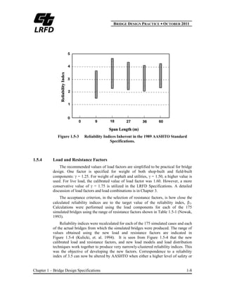
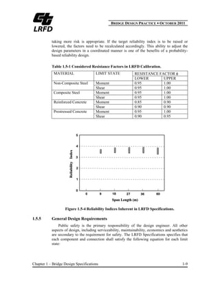
SlideShare a Scribd company logo
1 of 16
Download to read offline
BBRIDGE DESIGN PRACTICE ● OCTOBER 2011
Chapter 1 – Bridge Design Specifications 1-i
CHAPTER 1
BRIDGE DESIGN SPECIFICATIONS
TABLE OF CONTENTS
1.1 INTRODUCTION........................................................................................................... 1-1
1.2 LIMIT STATES .............................................................................................................. 1-2
1.3 ALLOWABLE STRESS DESIGN (ASD)...................................................................... 1-2
1.4 LOAD FACTOR DESIGN (LFD) .................................................................................. 1-3
1.5 LOAD AND RESISTANCE FACTOR DESIGN (LRFD)............................................. 1-4
1.5.1 Probability-Based Design ............................................................................... 1-4
1.5.2 Probabilistic Basis of the LRFD Specifications.............................................. 1-4
1.5.3 Calibration of Load and Resistance Factors.................................................... 1-6
1.5.4 Load and Resistance Factors........................................................................... 1-8
1.5.5 General Design Requirements......................................................................... 1-9
1.5.6 Serviceability Requirements ......................................................................... 1-10
1.5.7 Constructability Requirements...................................................................... 1-11
NOTATION ............................................................................................................................... 1-12
REFERENCES........................................................................................................................... 1-13
BBRIDGE DESIGN PRACTICE ● OCTOBER 2011
Chapter 1 – Bridge Design Specifications 1-ii
This page is intentionally left blank.
BBRIDGE DESIGN PRACTICE ● OCTOBER 2011
Chapter 1 – Bridge Design Specifications 1-1
CHAPTER 1
BRIDGE DESIGN SPECIFICATIONS
1.1 INTRODUCTION
The main purpose of bridge design specifications is to ensure bridge safety such
that minimum resistances or capacities, in terms of strength, stiffness, and stability of
each bridge component and the whole bridge structural system exceed the potential
maximum demands or force effects due to various loads during its design life. The
first national standard for highway bridge design and construction in the United
States, “Standard Specifications for Highway Bridges and Incidental Structures” was
published by the American Association of State Highway Officials (AASHO) in
1927, the predecessor to the American Association of State Highway and
Transportation Officials (AASHTO). Design theory and practice have evolved
significantly due to increased understanding of structural behavior and loading
phenomena gained through research. Prior to 1970, the sole design philosophy was
allowable stress design (ASD). Beginning in early 1970, a new design philosophy
referred to as load factor design (LFD) was introduced. The latest version entitled
“Standard Specifications for Highway Bridges” (Standard Specifications) is the final
17th Edition (AASHTO 2002) and includes both ASD and LFD philosophies.
Reliability-based and probability-based load and resistance factor design (LRFD)
philosophy was first adopted in “AASHTO LRFD Bridge Design Specifications”
(LRFD Specifications) (AASHTO 1994) and continues in the 5th Edition (AASHTO
2010). The LRFD Specifications had not been widely used until AASHTO
discontinued updating of its Standard Specifications in 2003.
ASD, LFD, and LRFD are distinct design philosophies and methods. ASD does
not recognize that some loads are more variable than others. LFD brings the major
philosophical change of recognizing that some loads are more accurately represented
than others. LRFD is a logical extension of the LFD procedure and provides a
mechanism to more systematically and rationally select the load and resistance
factors with uniform margins of safety.
The LRFD Specifications with California Amendments has been implemented
for the all new bridge designs in the State of California since 2006. The latest version
of California Amendments to the LRFD Specifications (AASHTO 2007) was
published in 2008 (Caltrans 2008). This chapter will briefly describe the general
concepts and backgrounds of ASD and LFD but primarily discuss the LRFD
philosophy. A detailed discussion may be found in Kulicki (1999).
BBRIDGE DESIGN PRACTICE ● OCTOBER 2011
Chapter 1 – Bridge Design Specifications 1-2
1.2 LIMIT STATES
The design specifications are written to establish an acceptable level of safety for
different loading cases. “Limit states” is a terminology for treating safety issues in
modern specifications. A limit state is a condition beyond which the bridge or
component ceases to satisfy the provisions for which it was designed. Limit states
may be expressed by functional requirements such as the limiting deformation, stress
or cracks, or by safety requirements such as the maximum strength. The design
provisions make certain that the probability of exceeding a limit state is acceptably
small by stipulating combinations of nominal loads and load factors, as well as
resistances and resistance factors that are consistent with the design assumptions. The
following four limit states are specified in the LRFD Specifications (AASHTO
2007):
Service Limit State: Deals with restrictions on stress, deformation and crack
width under regular service conditions. These provisions are intended to
ensure the bridge performs acceptably during its design life.
Fatigue and Fracture Limit State: The fatigue limit state deals with
restrictions on stress range under specified truck loading reflecting the
number of expected stress range excursions. The fracture limit state is to
establish a set of material toughness requirements. These provisions are
intended to limit crack growth under repetitive loads to prevent fracture
during its design life.
Strength Limit State: Ensures that strength and stability, both local and
global, are provided to resist the statistically-significant load combinations
during the life of a bridge. The overall structural integrity is expected to be
maintained.
Extreme Event Limit State: Ensures the structural survival of a bridge during
a major earthquake; collision by a vessel, vehicle or ice flow, or possibly
under scour conditions. These provisions deal with circumstances considered
to be unique occurrences whose return period is significantly greater than the
design life of a bridge. The probability of a joint occurrence of these events is
extremely low, and, therefore, they are applied separately. Under these
extreme conditions, the structure is expected to undergo considerable
inelastic deformation.
1.3 ALLOWABLE STRESS DESIGN (ASD)
ASD, also known as working stress design (WSD) or service load design, is
based on the concept that the maximum applied stress in a structural component not
exceed a certain allowable stress under normal service or working conditions. The
general ASD design equation can be expressed as:
BBRIDGE DESIGN PRACTICE ● OCTOBER 2011
Chapter 1 – Bridge Design Specifications 1-3
FS
R
Q n
i (1.3-1)
where Qi is a load effect; Rn is the nominal resistance and FS is a factor of safety.
The left side of Equation 1.3-1 represents working stress or service load effects.
The right side of Equation 1.3-1 means allowable stress. The load effect Qi is
obtained by an elastic structural analysis for a specified load, while the allowable
stress (Rn/FS) is the nominal limiting stress such as yielding, instability or fracture
divided by a safety factor. The magnitude of a factor of safety is primarily based on
past experience and engineering judgment. For example, the factors of safety for
axial tension and axial compression in structural steel are 1.82 and 2.12, respectively
in the Standard Specifications (AASHTO 2002).
The ASD treats each load in a given load combination as equal from the view
point of statistical variability. It does not consider the probability of both a higher
than expected load and a lower than expected strength occurring simultaneously.
They are both taken care of by the factor of safety. Although there are some
drawbacks to ASD, bridges designed based on ASD have served very well with
safety inherent in the system.
1.4 LOAD FACTOR DESIGN (LFD)
LFD, also known as ultimate or strength design, mainly recognizes that the live
load such as vehicular loads and wind forces, in particular, is more variable than the
dead load. This concept is achieved by using different multipliers, i.e., load factors on
dead and live loads. The general LFD design equation can be expressed as:
nii RQ (1.4-1)
where i is a load factor and is the strength reduction factor.
The nominal resistance is usually based on either loss of stability of a component
or inelastic cross-sectional strength. In some cases, the resistance is reduced by a
“strength reduction factor”, , which is based on the possibility that a component
may be undersized, the material may be under strength, or the method of calculation
may be less accurate. It should be pointed out, however, that the probability of a joint
occurrence of higher than expected loads and less than the expected resistance is not
considered.
One major disadvantage of LFD is that the load factors and resistance factors
were not calibrated in a manner that takes into account the statistical variability of
design parameters in nature, although the calibration for a simple-span of a 40-foot
steel girder was performed by Vincent (1969).
BBRIDGE DESIGN PRACTICE ● OCTOBER 2011
Chapter 1 – Bridge Design Specifications 1-4
1.5 LOAD AND RESISTANCE FACTOR DESIGN (LRFD)
1.5.1 Probability-Based Design
Probability-based design is to ensure that probability of failure of a structure is
less than a level acceptable to society. It directly takes into account the statistical
mean resistance, the statistical mean loads, the nominal or notional value of
resistance, the nominal or notional value of the loads and the dispersion of resistance
and loads as measured by either the standard deviation or the coefficient of variation.
Direct probability-based design that computes the probability of failure for a given
set of loads, statistical data and the estimate of the nominal resistance of the
component has been used in numerous engineering disciplines but had not been
widely used in bridge engineering.
1.5.2 Probabilistic Basis of the LRFD Specifications
The probability-based LRFD Specifications center around the load effects Q and
the resistances R modeled as statistically independent random variables (Ravindra
and Galambos 1978; Ellingwood, et. al. 1982; Kulicki, et. al. 1994). Figure 1.5-1
shows the relative frequency distributions for Q and R as separate curves. The mean
value of the load effects (Q ) and the mean value of the resistance ( R ) are also
shown. Qn and Rn are the nominal value of the load effects and the resistance,
respectively. and are the resistance and the load factor, respectively.
Figure 1.5-1 Relative Frequency Distribution of Load Effect Q and Resistance R.
As long as the resistance R is greater than the load effects Q, a margin of safety
for a particular limit state exists. However, since Q and R are random variables in
reality, there is a small probability that R may be less than Q. In other words, the
BBRIDGE DESIGN PRACTICE ● OCTOBER 2011
Chapter 1 – Bridge Design Specifications 1-5
probability of R < Q as shown as the overlap shadow area in Figure 1.5-1 is related to
the relative positioning of R andQ and their dispersions. For both the load effect and
the resistance, a second value somewhat offset from the mean value, is the “nominal”
value. Designers calculate these values for the load effect and the resistance. The
objective of the reliability-based or probability-based design philosophy is to separate
the distribution of resistance from the distribution of load effect, such that the area of
overlap, i.e., the area where load effect is greater than resistance, is acceptably small.
In the LRFD Specifications, load factors and resistance factors were developed
together in a way that forces the relationship between the resistance and load effect to
be such that the area of overlap in Figure 1.5-1 is less than or equal to the value that
AASHTO accepts.
Probability of “exceedance” or “achievement of a limit state” can be examined
by comparing R and Q as shown in Figure 1.5-2. Potential structural failure is
represented by the left side region. The distance between the “exceedance” line and
the mean value of the function of R-Q is defined as , where is the standard
deviation of the function of R-Q and is called the “reliability index” or “safety
index”. The larger is, the greater the margin of safety.
Figure 1.5-2 Reliability Index.
The probability of R < Q depends on the distribution shapes of each of many
variables (material, loads, etc.). Usually, the mean values and the standard deviations
or the coefficients of variation of many variables involved in R and Q can be
estimated. By applying the simple advanced first-order second-moment method
(Ravindra and Galambos 1978; Kulicki et. al. 1994) and assuming that both the
resistance and load effect are normal random variables, the following reliability index
equation can be obtained:
BBRIDGE DESIGN PRACTICE ● OCTOBER 2011
Chapter 1 – Bridge Design Specifications 1-6
22
QR
QR
(1.5-1)
where R and Q are the coefficients of variation of the resistance R and the load
effect Q, respectively.
Considering variations of both the load effect and the resistance, the basic design
equations can be expressed as:
ii xQR (1.5-2)
Introducing as the ratio of the mean value divided by the nominal value called
the "bias" leads to:
ii xR
1
(1.5-3)
Solving for the resistance factor from Equations 1.5-3 and 1.5-1 yields:
22
QR
ii
Q
(1.5-4)
It is seen that there are three unknowns, i.e., the resistance factor, , the
reliability index, , and the load factor, .
The reliability index is very useful. It can give an indication of the consistency of
safety for a bridge designed using traditional methods. It also can be used to establish
new methods which will have consistent margins of safety. Most importantly, it is a
comparative indicator. One group of bridges having a reliability index which is
greater than a second group of bridges has more inherent safety. A group of existing
bridges designed by either ASD or LFD formed the basis for determining the target,
or code-specified reliability index and the load and resistance factors in the LRFD
Specifications (Kulicki et. al. 1994).
1.5.3 Calibration of Load and Resistance Factors
A target value of the reliability index , usually denoted T, is chosen by a code-
writing body. Equation 1.5-4 still indicates that both the load and resistance factors
must be found. One way to solve this problem is to select the load factors and then
calculate the resistance factors. This process has been used by several code-writing
authorities (AASHTO 1994; OMTC 1994; CSA 1998). The basic steps of calibration
(Nowak, 1993) of the load and resistance factors for the LRFD Specifications were:
Develop a database of sample current bridges
Extract load effects as percentage of total load
Estimate the reliability indices implicit in current designs
BBRIDGE DESIGN PRACTICE ● OCTOBER 2011
Chapter 1 – Bridge Design Specifications 1-7
Quantify variability in loads and materials by deciding on coefficients of
variation
Assume load factors
Vary resistance factors until suitable reliability indices result
Approximately 200 representative bridges (Nowak, 1993) were selected from
various regions of the United States by requesting sample bridge plans from various
states. The selection was based on structural-type, material, and geographic location
to represent a full-range of materials and design loads and practices as they vary
around the country.
Statistically-projected live load and the notional values of live load effects were
calculated. Resistance was calculated in terms of the moment and the shear capacity
for each structure according to the prevailing requirements, in this case the AASHTO
Standard Specifications (AASHTO 1989) for load factor design. Based on the
relative amounts of the loads identified for each of the combinations of span and
spacing and type of construction indicated by the database, a simulated set of 175
bridges was developed. The simulated group was comprised of non-composite steel
girder bridges, composite steel girder bridges, reinforced concrete T-beam bridges,
and prestressed concrete I-beam bridges.
The reliability indices were calculated for each simulated and each actual bridge
for both the shear and the moment. The range of reliability indices which resulted
from this calibration process is presented in Figure 1.5-3 (Kulicki, et. al. 1994). It can
be seen that a wide-range of values were obtained using the Standard Specifications,
but this was anticipated based on previous calibration work done for the Ontario
Highway Bridge Design Code (Nowak, 1979).
These calculated reliability indices, as well as past calibration of other
specifications, served as a basis for the selection of the target reliability index, T. A
target reliability index of 3.5 was selected for the Ontario Highway Bridge Design
Code (OMTC 1994) and other reliability-based specifications. A consideration of the
data shown in Figure 1.5-3 indicates that a of 3.5 is representative of past LFD
practice. Hence, this value was selected as a target for the calibration of the LRFD
Specifications.
BBRIDGE DESIGN PRACTICE ● OCTOBER 2011
Chapter 1 – Bridge Design Specifications 1-8
Figure 1.5-3 Reliability Indices Inherent in the 1989 AASHTO Standard
Specifications.
1.5.4 Load and Resistance Factors
The recommended values of load factors are simplified to be practical for bridge
design. One factor is specified for weight of both shop-built and field-built
components: = 1.25. For weight of asphalt and utilities, = 1.50, a higher value is
used. For live load, the calibrated value of load factor was 1.60. However, a more
conservative value of = 1.75 is utilized in the LRFD Specifications. A detailed
discussion of load factors and load combinations is in Chapter 3.
The acceptance criterion, in the selection of resistance factors, is how close the
calculated reliability indices are to the target value of the reliability index, T.
Calculations were performed using the load components for each of the 175
simulated bridges using the range of resistance factors shown in Table 1.5-1 (Nowak,
1993).
Reliability indices were recalculated for each of the 175 simulated cases and each
of the actual bridges from which the simulated bridges were produced. The range of
values obtained using the new load and resistance factors are indicated in
Figure 1.5-4 (Kulicki, et. al. 1994). It is seen from Figure 1.5-4 that the new
calibrated load and resistance factors, and new load models and load distribution
techniques work together to produce very narrowly-clustered reliability indices. This
was the objective of developing the new factors. Correspondence to a reliability
index of 3.5 can now be altered by AASHTO when either a higher level of safety or
BBRIDGE DESIGN PRACTICE ● OCTOBER 2011
Chapter 1 – Bridge Design Specifications 1-9
taking more risk is appropriate. If the target reliability index is to be raised or
lowered, the factors need to be recalculated accordingly. This ability to adjust the
design parameters in a coordinated manner is one of the benefits of a probability-
based reliability design.
Table 1.5-1 Considered Resistance Factors in LRFD Calibration.
MATERIAL LIMIT STATE RESISTANCE FACTOR
LOWER UPPER
Non-Composite Steel Moment 0.95 1.00
Shear 0.95 1.00
Composite Steel Moment 0.95 1.00
Shear 0.95 1.00
Reinforced Concrete Moment 0.85 0.90
Shear 0.90 0.90
Prestressed Concrete Moment 0.95 1.00
Shear 0.90 0.95
Figure 1.5-4 Reliability Indices Inherent in LRFD Specifications.
1.5.5 General Design Requirements
Public safety is the primary responsibility of the design engineer. All other
aspects of design, including serviceability, maintainability, economics and aesthetics
are secondary to the requirement for safety. The LRFD Specifications specifies that
each component and connection shall satisfy the following equation for each limit
state:
BBRIDGE DESIGN PRACTICE ● OCTOBER 2011
Chapter 1 – Bridge Design Specifications 1-10
rniii RRQ (AASHTO 1.3.2.1-1)
where i is a load modifier relating to ductility, redundancy, and operational
importance and Rr is the factored resistance.
For loads for which a maximum value of i is appropriate:
950.IRDi (AASHTO 1.3.2.1-2)
For loads for which a minimum value of i is appropriate:
01
1
.
IRD
i (AASHTO 1.3.2.1-3)
where D , R and I are factors relating to ductility, redundancy, and operational
importance, respectively. California Amendments (Caltrans 2008) specifies that the
value of 1.0 shall be used for D, R and I until their applications are further studied.
1.5.6 Serviceability Requirements
The LRFD Specifications address serviceability from the view points of
durability, restriction of stresses, cracking, corrosion, and deformation - all in
conjunction with contract documents to achieve the desired design life. Bridge
designers also need to be mindful of ease in inspection and maintainability, as
addressed in the Manual for Bridge Evaluation (AASHTO 2008).
Durability is to be assured through contract documents calling for high quality
materials and requiring that those materials that are subject to deterioration from
moisture content and/or salt attack be protected. Good workmanship is also important
for good durability.
Maintainability is treated in the specifications in a similar manner to durability; a
list of desirable attributes to be considered is provided.
Inspectability is to be assured by providing adequate means for inspectors to
view all parts of the structure which have structural or maintenance significance.
Bridge inspection can be very expensive and is a recurring cost. Therefore, the cost
of providing walkways and other means of access and adequate room for people and
inspection equipment to be moved about on the structure is usually a good
investment.
Rider comfort is often rationalized as a basis for deflection control. As a
compromise between the need for establishing comfort levels and the lack of
compelling evidence that deflection was the cause of structural distress, the
deflection criteria, other than those pertaining to relative deflections of ribs of
orthotropic decks and components of some wood decks, were written as voluntary
provisions to be activated by those states that so choose. Deflection limits, stated as
span length divided by some number, were established for most cases, and additional
BBRIDGE DESIGN PRACTICE ● OCTOBER 2011
Chapter 1 – Bridge Design Specifications 1-11
provisions of absolute relative displacement between planks and panels of wooden
decks and ribs of orthotropic decks were also added. Similarly, optional criteria were
established for a span-to-depth ratio for guidance primarily in starting preliminary
designs, but also as a mechanism for checking when a given design deviates
significantly from past successful practice.
User comfort on pedestrian bridges is addressed in the LRFD Guide
Specifications for the Design of Pedestrian Bridges (AASHTO 2009).
1.5.7 Constructability Requirements
The following provisions in the LRFD Specifications are related to
constructability:
Design bridges so that they can be fabricated and built without undue
difficulty and with control over locked in construction force effects,
Document one feasible method of construction in the contract documents,
unless the type of construction is self-evident, and
Indicate clearly the need to provide strengthening and/or temporary bracing
or support during erection, but not requiring the complete design thereof.
BBRIDGE DESIGN PRACTICE ● OCTOBER 2011
Chapter 1 – Bridge Design Specifications 1-12
NOTATION
FS = factor of safety
Q = load effects
Q = mean value of the load effect
Qi = a load effect
R = resistance
Rn = nominal resistance
R = mean value of the resistance
Rr = factored resistance
i = a load factor
= load factor
= ratio of the mean value divided by the nominal value, called the “bias”
= reliability index
T = target reliability index
= resistance factor
D = a factor relating to ductility = 1.0
R = a factor relating to redundancy = 1.0
I = a factor relating to operational importance = 1.0
i = a load modifier, a factor relating to ductility, redundancy, and operation
importance
= standard deviation
R = coefficient of variation of the resistance R
Q = coefficient of variation of the load effect Q
BBRIDGE DESIGN PRACTICE ● OCTOBER 2011
Chapter 1 – Bridge Design Specifications 1-13
REFERENCES
1. AASHO, (1927). Standard Specifications for Highway Bridges and Incidental Structures,
American Association of State Highway Officials, Washington, D.C.
2. AASHTO, (1989). Standard Specifications for Highway Bridges, 14th
Edition, American
Association of State Highway and Transportation Officials, Washington, D.C.
3. AASHTO, (1994). AASHTO LRFD Bridge Design Specifications, 1st
Edition, American
Association of State Highway and Transportation Officials, Washington, D.C.
4. AASHTO, (2002). Standard Specifications for Highway Bridges, 17th
Edition, American
Association of State Highway and Transportation Officials, Washington, D.C.
5. AASHTO, (2007). AASHTO LRFD Bridge Design Specifications, 4th
Edition, American
Association of State Highway and Transportation Officials, Washington, D.C.
6. AASHTO, (2008). The Manual for Bridge Evaluation, First Edition, American
Association of State Highway and Transportation Officials, Washington, D.C.
7. AASHTO, (2009). AASHTO LRFD Guide Specifications for the Design of Pedestrian
Bridges, American Association of State Highway and Transportation Officials,
Washington, D.C.
8. AASHTO, (2010). AASHTO LRFD Bridge Design Specifications, 5th
Edition, American
Association of State Highway and Transportation Officials, Washington, D.C.
9. Caltrans, (2008). California Amendments to AASHTO LRFD Bridge Design
Specifications, California Department of Transportation, Sacramento, CA.
10. CSA, (1998). Canadian Highway Bridge Design Code, Canadian Standards Association,
Rexdale, Ontario, Canada.
11. Ellingwood, B.E., MacGregor, J.G., Galambos, T.V., and Cornell, C.A. (1982).
“Probability-Based Load Criteria: Load Factors and Load Combinations,” Journal of
Structural Division, ASCE, 108(5), 1337-1353.
12. Kulicki, J.M. (1999). “Chapter 5: Design Philosophies for Highway Bridges,” Bridge
Engineering Handbook, Edited by Chen, W.F. and Duan, L., CRC Press, Boca Raton,
FL.
13. Kulicki, J.M., Mertz, D.R. and Wassef, W.G. (1994). “LRFD Design of Highway
Bridges,” NHI Course 13061, Federal Highway Administration, Washington, D. C.
BBRIDGE DESIGN PRACTICE ● OCTOBER 2011
Chapter 1 – Bridge Design Specifications 1-14
14. Nowak, A.S. (1993). “Calibration of LRFD Bridge Design Code,” Department of Civil
and Environmental Engineering Report UMCE 92-25, University of Michigan, Ann
Arbor, MI.
15. Nowak, A.S. and Lind, N.C. (1979). “Practical Bridge Code Calibration,” ASCE,
Journal of the Structural Division, ASCE, 105(ST12), 2497-2510
16. OMTC, (1994). Ontario Highway Bridge Design Code, Ontario Ministry of
Transportation and Communications, Toronto, Ontario, Canada.
17. Ravindra, M.K., and Galambos, T.V. (1978). “Load and Resistance Factor Design for
Steel,” Journal of Structural Division, ASCE, 104(ST9), 1337-1353.
18. Vincent, G.S. (1969). “Tentative Criteria for Load Factor Design of Steel Highway
Bridges,” AISI Bulletin 15, American Iron and Steel Institute, Washington, DC.

More Related Content

What's hot

Steel strucure lec # (3)
Steel strucure lec #  (3)Steel strucure lec #  (3)
Steel strucure lec # (3)Civil Zone
 
Investigation on performance based non linear pushover analysis of flat plate...
Investigation on performance based non linear pushover analysis of flat plate...Investigation on performance based non linear pushover analysis of flat plate...
Investigation on performance based non linear pushover analysis of flat plate...Yousuf Dinar
 
Progressive Collapse Analysis of RC Buildings with consideration of Effect of...
Progressive Collapse Analysis of RC Buildings with consideration of Effect of...Progressive Collapse Analysis of RC Buildings with consideration of Effect of...
Progressive Collapse Analysis of RC Buildings with consideration of Effect of...ijsrd.com
 
Solving statically indeterminate structure: moment coefficient method
Solving statically indeterminate structure:  moment coefficient methodSolving statically indeterminate structure:  moment coefficient method
Solving statically indeterminate structure: moment coefficient methodcivilengineeringfreedownload
 
Progressive collapse analysis
Progressive collapse analysisProgressive collapse analysis
Progressive collapse analysisjeyanthi4
 
Progressive collapse analysis of reinforced concrete
Progressive collapse analysis of reinforced concreteProgressive collapse analysis of reinforced concrete
Progressive collapse analysis of reinforced concreteeSAT Publishing House
 

What's hot (6)

Steel strucure lec # (3)
Steel strucure lec #  (3)Steel strucure lec #  (3)
Steel strucure lec # (3)
 
Investigation on performance based non linear pushover analysis of flat plate...
Investigation on performance based non linear pushover analysis of flat plate...Investigation on performance based non linear pushover analysis of flat plate...
Investigation on performance based non linear pushover analysis of flat plate...
 
Progressive Collapse Analysis of RC Buildings with consideration of Effect of...
Progressive Collapse Analysis of RC Buildings with consideration of Effect of...Progressive Collapse Analysis of RC Buildings with consideration of Effect of...
Progressive Collapse Analysis of RC Buildings with consideration of Effect of...
 
Solving statically indeterminate structure: moment coefficient method
Solving statically indeterminate structure:  moment coefficient methodSolving statically indeterminate structure:  moment coefficient method
Solving statically indeterminate structure: moment coefficient method
 
Progressive collapse analysis
Progressive collapse analysisProgressive collapse analysis
Progressive collapse analysis
 
Progressive collapse analysis of reinforced concrete
Progressive collapse analysis of reinforced concreteProgressive collapse analysis of reinforced concrete
Progressive collapse analysis of reinforced concrete
 

Similar to Bdp 1

AASHTO Steel Bridge Design Handbook Volume 10
AASHTO Steel Bridge Design Handbook Volume 10AASHTO Steel Bridge Design Handbook Volume 10
AASHTO Steel Bridge Design Handbook Volume 10Walid Alaywan
 
Reliability Analysis of Jacket Platforms in Malaysia-Environmental Load Factors
Reliability Analysis of Jacket Platforms in Malaysia-Environmental Load FactorsReliability Analysis of Jacket Platforms in Malaysia-Environmental Load Factors
Reliability Analysis of Jacket Platforms in Malaysia-Environmental Load FactorsNelson Cossa
 
Masonry Code Of Practice Amp
Masonry Code Of Practice   AmpMasonry Code Of Practice   Amp
Masonry Code Of Practice AmpTeja Ande
 
DESIGN OF RC STRUCTURES.pdf
DESIGN OF RC STRUCTURES.pdfDESIGN OF RC STRUCTURES.pdf
DESIGN OF RC STRUCTURES.pdfPagolchala
 
AASHTO Steel Bridge Design Handbook Volume 07
AASHTO Steel Bridge Design Handbook Volume 07 AASHTO Steel Bridge Design Handbook Volume 07
AASHTO Steel Bridge Design Handbook Volume 07 Walid Alaywan
 
Lecture_No_1 (Steel structures) (2).pdf
Lecture_No_1 (Steel structures) (2).pdfLecture_No_1 (Steel structures) (2).pdf
Lecture_No_1 (Steel structures) (2).pdfWaliEdwardian1
 
Planning, Analysis, Design and Detailing of degree college building by adapti...
Planning, Analysis, Design and Detailing of degree college building by adapti...Planning, Analysis, Design and Detailing of degree college building by adapti...
Planning, Analysis, Design and Detailing of degree college building by adapti...IRJET Journal
 
04-LRFD Concept (Steel Structural Design & Prof. Shehab Mourad)
04-LRFD Concept (Steel Structural Design & Prof. Shehab Mourad)04-LRFD Concept (Steel Structural Design & Prof. Shehab Mourad)
04-LRFD Concept (Steel Structural Design & Prof. Shehab Mourad)Hossam Shafiq II
 
RELIABILITY ANALYSIS OF CONCRETE BEAMS: A Complete Review
RELIABILITY ANALYSIS OF CONCRETE BEAMS: A Complete ReviewRELIABILITY ANALYSIS OF CONCRETE BEAMS: A Complete Review
RELIABILITY ANALYSIS OF CONCRETE BEAMS: A Complete ReviewIRJET Journal
 
A Comprehensive Analysis of Foundation Design Approaches
A Comprehensive Analysis of Foundation Design ApproachesA Comprehensive Analysis of Foundation Design Approaches
A Comprehensive Analysis of Foundation Design ApproachesSamirsinh Parmar
 
ULTIMATE LIMIT STATE ASSESSMENT OF STIFFENED PANEL STRUCTURES FOR VERY LARGE ...
ULTIMATE LIMIT STATE ASSESSMENT OF STIFFENED PANEL STRUCTURES FOR VERY LARGE ...ULTIMATE LIMIT STATE ASSESSMENT OF STIFFENED PANEL STRUCTURES FOR VERY LARGE ...
ULTIMATE LIMIT STATE ASSESSMENT OF STIFFENED PANEL STRUCTURES FOR VERY LARGE ...ijmech
 
Session 5 design of rcc structural elements PROF YADUNANDAN
Session 5 design of rcc structural elements  PROF YADUNANDANSession 5 design of rcc structural elements  PROF YADUNANDAN
Session 5 design of rcc structural elements PROF YADUNANDANAjit Sabnis
 
DESIGN OF RCC ELEMENTS SESSION 5 PROF. YADUNANDAN
DESIGN OF RCC ELEMENTS SESSION 5 PROF. YADUNANDANDESIGN OF RCC ELEMENTS SESSION 5 PROF. YADUNANDAN
DESIGN OF RCC ELEMENTS SESSION 5 PROF. YADUNANDANAjit Sabnis
 
steel design sultan.pptx
steel design sultan.pptxsteel design sultan.pptx
steel design sultan.pptxcadlab8101
 
TALAT Lecture 2204: Design Philosophy
TALAT Lecture 2204: Design PhilosophyTALAT Lecture 2204: Design Philosophy
TALAT Lecture 2204: Design PhilosophyCORE-Materials
 

Similar to Bdp 1 (20)

AASHTO Steel Bridge Design Handbook Volume 10
AASHTO Steel Bridge Design Handbook Volume 10AASHTO Steel Bridge Design Handbook Volume 10
AASHTO Steel Bridge Design Handbook Volume 10
 
Reliability Analysis of Jacket Platforms in Malaysia-Environmental Load Factors
Reliability Analysis of Jacket Platforms in Malaysia-Environmental Load FactorsReliability Analysis of Jacket Platforms in Malaysia-Environmental Load Factors
Reliability Analysis of Jacket Platforms in Malaysia-Environmental Load Factors
 
Steel is800review
Steel is800reviewSteel is800review
Steel is800review
 
Masonry Code Of Practice Amp
Masonry Code Of Practice   AmpMasonry Code Of Practice   Amp
Masonry Code Of Practice Amp
 
Tub_Girder_Draft_Linked
Tub_Girder_Draft_LinkedTub_Girder_Draft_Linked
Tub_Girder_Draft_Linked
 
state-method.ppt
state-method.pptstate-method.ppt
state-method.ppt
 
DESIGN OF RC STRUCTURES.pdf
DESIGN OF RC STRUCTURES.pdfDESIGN OF RC STRUCTURES.pdf
DESIGN OF RC STRUCTURES.pdf
 
Limit state method
Limit state methodLimit state method
Limit state method
 
AASHTO Steel Bridge Design Handbook Volume 07
AASHTO Steel Bridge Design Handbook Volume 07 AASHTO Steel Bridge Design Handbook Volume 07
AASHTO Steel Bridge Design Handbook Volume 07
 
Lecture_No_1 (Steel structures) (2).pdf
Lecture_No_1 (Steel structures) (2).pdfLecture_No_1 (Steel structures) (2).pdf
Lecture_No_1 (Steel structures) (2).pdf
 
Planning, Analysis, Design and Detailing of degree college building by adapti...
Planning, Analysis, Design and Detailing of degree college building by adapti...Planning, Analysis, Design and Detailing of degree college building by adapti...
Planning, Analysis, Design and Detailing of degree college building by adapti...
 
04-LRFD Concept (Steel Structural Design & Prof. Shehab Mourad)
04-LRFD Concept (Steel Structural Design & Prof. Shehab Mourad)04-LRFD Concept (Steel Structural Design & Prof. Shehab Mourad)
04-LRFD Concept (Steel Structural Design & Prof. Shehab Mourad)
 
RELIABILITY ANALYSIS OF CONCRETE BEAMS: A Complete Review
RELIABILITY ANALYSIS OF CONCRETE BEAMS: A Complete ReviewRELIABILITY ANALYSIS OF CONCRETE BEAMS: A Complete Review
RELIABILITY ANALYSIS OF CONCRETE BEAMS: A Complete Review
 
A Comprehensive Analysis of Foundation Design Approaches
A Comprehensive Analysis of Foundation Design ApproachesA Comprehensive Analysis of Foundation Design Approaches
A Comprehensive Analysis of Foundation Design Approaches
 
ULTIMATE LIMIT STATE ASSESSMENT OF STIFFENED PANEL STRUCTURES FOR VERY LARGE ...
ULTIMATE LIMIT STATE ASSESSMENT OF STIFFENED PANEL STRUCTURES FOR VERY LARGE ...ULTIMATE LIMIT STATE ASSESSMENT OF STIFFENED PANEL STRUCTURES FOR VERY LARGE ...
ULTIMATE LIMIT STATE ASSESSMENT OF STIFFENED PANEL STRUCTURES FOR VERY LARGE ...
 
Session 5 design of rcc structural elements PROF YADUNANDAN
Session 5 design of rcc structural elements  PROF YADUNANDANSession 5 design of rcc structural elements  PROF YADUNANDAN
Session 5 design of rcc structural elements PROF YADUNANDAN
 
DESIGN OF RCC ELEMENTS SESSION 5 PROF. YADUNANDAN
DESIGN OF RCC ELEMENTS SESSION 5 PROF. YADUNANDANDESIGN OF RCC ELEMENTS SESSION 5 PROF. YADUNANDAN
DESIGN OF RCC ELEMENTS SESSION 5 PROF. YADUNANDAN
 
steel design sultan.pptx
steel design sultan.pptxsteel design sultan.pptx
steel design sultan.pptx
 
TALAT Lecture 2204: Design Philosophy
TALAT Lecture 2204: Design PhilosophyTALAT Lecture 2204: Design Philosophy
TALAT Lecture 2204: Design Philosophy
 
122928566 buckling
122928566 buckling122928566 buckling
122928566 buckling
 

Recently uploaded

AMBER GRAIN EMBROIDERY | Growing folklore elements | Root-based materials, w...
AMBER GRAIN EMBROIDERY | Growing folklore elements |  Root-based materials, w...AMBER GRAIN EMBROIDERY | Growing folklore elements |  Root-based materials, w...
AMBER GRAIN EMBROIDERY | Growing folklore elements | Root-based materials, w...BarusRa
 
Peaches App development presentation deck
Peaches App development presentation deckPeaches App development presentation deck
Peaches App development presentation decktbatkhuu1
 
💫✅jodhpur 24×7 BEST GENUINE PERSON LOW PRICE CALL GIRL SERVICE FULL SATISFACT...
💫✅jodhpur 24×7 BEST GENUINE PERSON LOW PRICE CALL GIRL SERVICE FULL SATISFACT...💫✅jodhpur 24×7 BEST GENUINE PERSON LOW PRICE CALL GIRL SERVICE FULL SATISFACT...
💫✅jodhpur 24×7 BEST GENUINE PERSON LOW PRICE CALL GIRL SERVICE FULL SATISFACT...sonalitrivedi431
 
VIP Model Call Girls Kalyani Nagar ( Pune ) Call ON 8005736733 Starting From ...
VIP Model Call Girls Kalyani Nagar ( Pune ) Call ON 8005736733 Starting From ...VIP Model Call Girls Kalyani Nagar ( Pune ) Call ON 8005736733 Starting From ...
VIP Model Call Girls Kalyani Nagar ( Pune ) Call ON 8005736733 Starting From ...SUHANI PANDEY
 
The history of music videos a level presentation
The history of music videos a level presentationThe history of music videos a level presentation
The history of music videos a level presentationamedia6
 
VVIP CALL GIRLS Lucknow 💓 Lucknow < Renuka Sharma > 7877925207 Escorts Service
VVIP CALL GIRLS Lucknow 💓 Lucknow < Renuka Sharma > 7877925207 Escorts ServiceVVIP CALL GIRLS Lucknow 💓 Lucknow < Renuka Sharma > 7877925207 Escorts Service
VVIP CALL GIRLS Lucknow 💓 Lucknow < Renuka Sharma > 7877925207 Escorts Servicearoranaina404
 
(AISHA) Ambegaon Khurd Call Girls Just Call 7001035870 [ Cash on Delivery ] P...
(AISHA) Ambegaon Khurd Call Girls Just Call 7001035870 [ Cash on Delivery ] P...(AISHA) Ambegaon Khurd Call Girls Just Call 7001035870 [ Cash on Delivery ] P...
(AISHA) Ambegaon Khurd Call Girls Just Call 7001035870 [ Cash on Delivery ] P...ranjana rawat
 
VVIP Pune Call Girls Hadapsar (7001035870) Pune Escorts Nearby with Complete ...
VVIP Pune Call Girls Hadapsar (7001035870) Pune Escorts Nearby with Complete ...VVIP Pune Call Girls Hadapsar (7001035870) Pune Escorts Nearby with Complete ...
VVIP Pune Call Girls Hadapsar (7001035870) Pune Escorts Nearby with Complete ...Call Girls in Nagpur High Profile
 
Government polytechnic college-1.pptxabcd
Government polytechnic college-1.pptxabcdGovernment polytechnic college-1.pptxabcd
Government polytechnic college-1.pptxabcdshivubhavv
 
Top Rated Pune Call Girls Koregaon Park ⟟ 6297143586 ⟟ Call Me For Genuine S...
Top Rated  Pune Call Girls Koregaon Park ⟟ 6297143586 ⟟ Call Me For Genuine S...Top Rated  Pune Call Girls Koregaon Park ⟟ 6297143586 ⟟ Call Me For Genuine S...
Top Rated Pune Call Girls Koregaon Park ⟟ 6297143586 ⟟ Call Me For Genuine S...Call Girls in Nagpur High Profile
 
Kala jadu for love marriage | Real amil baba | Famous amil baba | kala jadu n...
Kala jadu for love marriage | Real amil baba | Famous amil baba | kala jadu n...Kala jadu for love marriage | Real amil baba | Famous amil baba | kala jadu n...
Kala jadu for love marriage | Real amil baba | Famous amil baba | kala jadu n...babafaisel
 
Call Girls Basavanagudi Just Call 👗 7737669865 👗 Top Class Call Girl Service ...
Call Girls Basavanagudi Just Call 👗 7737669865 👗 Top Class Call Girl Service ...Call Girls Basavanagudi Just Call 👗 7737669865 👗 Top Class Call Girl Service ...
Call Girls Basavanagudi Just Call 👗 7737669865 👗 Top Class Call Girl Service ...amitlee9823
 
Escorts Service Basapura ☎ 7737669865☎ Book Your One night Stand (Bangalore)
Escorts Service Basapura ☎ 7737669865☎ Book Your One night Stand (Bangalore)Escorts Service Basapura ☎ 7737669865☎ Book Your One night Stand (Bangalore)
Escorts Service Basapura ☎ 7737669865☎ Book Your One night Stand (Bangalore)amitlee9823
 
call girls in Vasundhra (Ghaziabad) 🔝 >༒8448380779 🔝 genuine Escort Service 🔝...
call girls in Vasundhra (Ghaziabad) 🔝 >༒8448380779 🔝 genuine Escort Service 🔝...call girls in Vasundhra (Ghaziabad) 🔝 >༒8448380779 🔝 genuine Escort Service 🔝...
call girls in Vasundhra (Ghaziabad) 🔝 >༒8448380779 🔝 genuine Escort Service 🔝...Delhi Call girls
 
Brookefield Call Girls: 🍓 7737669865 🍓 High Profile Model Escorts | Bangalore...
Brookefield Call Girls: 🍓 7737669865 🍓 High Profile Model Escorts | Bangalore...Brookefield Call Girls: 🍓 7737669865 🍓 High Profile Model Escorts | Bangalore...
Brookefield Call Girls: 🍓 7737669865 🍓 High Profile Model Escorts | Bangalore...amitlee9823
 
call girls in Dakshinpuri (DELHI) 🔝 >༒9953056974 🔝 genuine Escort Service 🔝✔️✔️
call girls in Dakshinpuri  (DELHI) 🔝 >༒9953056974 🔝 genuine Escort Service 🔝✔️✔️call girls in Dakshinpuri  (DELHI) 🔝 >༒9953056974 🔝 genuine Escort Service 🔝✔️✔️
call girls in Dakshinpuri (DELHI) 🔝 >༒9953056974 🔝 genuine Escort Service 🔝✔️✔️9953056974 Low Rate Call Girls In Saket, Delhi NCR
 
Pastel Portfolio _ by Slidesgo.pptx. Xxx
Pastel Portfolio _ by Slidesgo.pptx. XxxPastel Portfolio _ by Slidesgo.pptx. Xxx
Pastel Portfolio _ by Slidesgo.pptx. XxxSegundoManuelFaichin1
 
Editorial design Magazine design project.pdf
Editorial design Magazine design project.pdfEditorial design Magazine design project.pdf
Editorial design Magazine design project.pdftbatkhuu1
 

Recently uploaded (20)

AMBER GRAIN EMBROIDERY | Growing folklore elements | Root-based materials, w...
AMBER GRAIN EMBROIDERY | Growing folklore elements |  Root-based materials, w...AMBER GRAIN EMBROIDERY | Growing folklore elements |  Root-based materials, w...
AMBER GRAIN EMBROIDERY | Growing folklore elements | Root-based materials, w...
 
Peaches App development presentation deck
Peaches App development presentation deckPeaches App development presentation deck
Peaches App development presentation deck
 
B. Smith. (Architectural Portfolio.).pdf
B. Smith. (Architectural Portfolio.).pdfB. Smith. (Architectural Portfolio.).pdf
B. Smith. (Architectural Portfolio.).pdf
 
💫✅jodhpur 24×7 BEST GENUINE PERSON LOW PRICE CALL GIRL SERVICE FULL SATISFACT...
💫✅jodhpur 24×7 BEST GENUINE PERSON LOW PRICE CALL GIRL SERVICE FULL SATISFACT...💫✅jodhpur 24×7 BEST GENUINE PERSON LOW PRICE CALL GIRL SERVICE FULL SATISFACT...
💫✅jodhpur 24×7 BEST GENUINE PERSON LOW PRICE CALL GIRL SERVICE FULL SATISFACT...
 
VIP Model Call Girls Kalyani Nagar ( Pune ) Call ON 8005736733 Starting From ...
VIP Model Call Girls Kalyani Nagar ( Pune ) Call ON 8005736733 Starting From ...VIP Model Call Girls Kalyani Nagar ( Pune ) Call ON 8005736733 Starting From ...
VIP Model Call Girls Kalyani Nagar ( Pune ) Call ON 8005736733 Starting From ...
 
The history of music videos a level presentation
The history of music videos a level presentationThe history of music videos a level presentation
The history of music videos a level presentation
 
VVIP CALL GIRLS Lucknow 💓 Lucknow < Renuka Sharma > 7877925207 Escorts Service
VVIP CALL GIRLS Lucknow 💓 Lucknow < Renuka Sharma > 7877925207 Escorts ServiceVVIP CALL GIRLS Lucknow 💓 Lucknow < Renuka Sharma > 7877925207 Escorts Service
VVIP CALL GIRLS Lucknow 💓 Lucknow < Renuka Sharma > 7877925207 Escorts Service
 
(AISHA) Ambegaon Khurd Call Girls Just Call 7001035870 [ Cash on Delivery ] P...
(AISHA) Ambegaon Khurd Call Girls Just Call 7001035870 [ Cash on Delivery ] P...(AISHA) Ambegaon Khurd Call Girls Just Call 7001035870 [ Cash on Delivery ] P...
(AISHA) Ambegaon Khurd Call Girls Just Call 7001035870 [ Cash on Delivery ] P...
 
Call Girls Service Mukherjee Nagar @9999965857 Delhi 🫦 No Advance VVIP 🍎 SER...
Call Girls Service Mukherjee Nagar @9999965857 Delhi 🫦 No Advance  VVIP 🍎 SER...Call Girls Service Mukherjee Nagar @9999965857 Delhi 🫦 No Advance  VVIP 🍎 SER...
Call Girls Service Mukherjee Nagar @9999965857 Delhi 🫦 No Advance VVIP 🍎 SER...
 
VVIP Pune Call Girls Hadapsar (7001035870) Pune Escorts Nearby with Complete ...
VVIP Pune Call Girls Hadapsar (7001035870) Pune Escorts Nearby with Complete ...VVIP Pune Call Girls Hadapsar (7001035870) Pune Escorts Nearby with Complete ...
VVIP Pune Call Girls Hadapsar (7001035870) Pune Escorts Nearby with Complete ...
 
Government polytechnic college-1.pptxabcd
Government polytechnic college-1.pptxabcdGovernment polytechnic college-1.pptxabcd
Government polytechnic college-1.pptxabcd
 
Top Rated Pune Call Girls Koregaon Park ⟟ 6297143586 ⟟ Call Me For Genuine S...
Top Rated  Pune Call Girls Koregaon Park ⟟ 6297143586 ⟟ Call Me For Genuine S...Top Rated  Pune Call Girls Koregaon Park ⟟ 6297143586 ⟟ Call Me For Genuine S...
Top Rated Pune Call Girls Koregaon Park ⟟ 6297143586 ⟟ Call Me For Genuine S...
 
Kala jadu for love marriage | Real amil baba | Famous amil baba | kala jadu n...
Kala jadu for love marriage | Real amil baba | Famous amil baba | kala jadu n...Kala jadu for love marriage | Real amil baba | Famous amil baba | kala jadu n...
Kala jadu for love marriage | Real amil baba | Famous amil baba | kala jadu n...
 
Call Girls Basavanagudi Just Call 👗 7737669865 👗 Top Class Call Girl Service ...
Call Girls Basavanagudi Just Call 👗 7737669865 👗 Top Class Call Girl Service ...Call Girls Basavanagudi Just Call 👗 7737669865 👗 Top Class Call Girl Service ...
Call Girls Basavanagudi Just Call 👗 7737669865 👗 Top Class Call Girl Service ...
 
Escorts Service Basapura ☎ 7737669865☎ Book Your One night Stand (Bangalore)
Escorts Service Basapura ☎ 7737669865☎ Book Your One night Stand (Bangalore)Escorts Service Basapura ☎ 7737669865☎ Book Your One night Stand (Bangalore)
Escorts Service Basapura ☎ 7737669865☎ Book Your One night Stand (Bangalore)
 
call girls in Vasundhra (Ghaziabad) 🔝 >༒8448380779 🔝 genuine Escort Service 🔝...
call girls in Vasundhra (Ghaziabad) 🔝 >༒8448380779 🔝 genuine Escort Service 🔝...call girls in Vasundhra (Ghaziabad) 🔝 >༒8448380779 🔝 genuine Escort Service 🔝...
call girls in Vasundhra (Ghaziabad) 🔝 >༒8448380779 🔝 genuine Escort Service 🔝...
 
Brookefield Call Girls: 🍓 7737669865 🍓 High Profile Model Escorts | Bangalore...
Brookefield Call Girls: 🍓 7737669865 🍓 High Profile Model Escorts | Bangalore...Brookefield Call Girls: 🍓 7737669865 🍓 High Profile Model Escorts | Bangalore...
Brookefield Call Girls: 🍓 7737669865 🍓 High Profile Model Escorts | Bangalore...
 
call girls in Dakshinpuri (DELHI) 🔝 >༒9953056974 🔝 genuine Escort Service 🔝✔️✔️
call girls in Dakshinpuri  (DELHI) 🔝 >༒9953056974 🔝 genuine Escort Service 🔝✔️✔️call girls in Dakshinpuri  (DELHI) 🔝 >༒9953056974 🔝 genuine Escort Service 🔝✔️✔️
call girls in Dakshinpuri (DELHI) 🔝 >༒9953056974 🔝 genuine Escort Service 🔝✔️✔️
 
Pastel Portfolio _ by Slidesgo.pptx. Xxx
Pastel Portfolio _ by Slidesgo.pptx. XxxPastel Portfolio _ by Slidesgo.pptx. Xxx
Pastel Portfolio _ by Slidesgo.pptx. Xxx
 
Editorial design Magazine design project.pdf
Editorial design Magazine design project.pdfEditorial design Magazine design project.pdf
Editorial design Magazine design project.pdf
 

Bdp 1

  • 1. BBRIDGE DESIGN PRACTICE ● OCTOBER 2011 Chapter 1 – Bridge Design Specifications 1-i CHAPTER 1 BRIDGE DESIGN SPECIFICATIONS TABLE OF CONTENTS 1.1 INTRODUCTION........................................................................................................... 1-1 1.2 LIMIT STATES .............................................................................................................. 1-2 1.3 ALLOWABLE STRESS DESIGN (ASD)...................................................................... 1-2 1.4 LOAD FACTOR DESIGN (LFD) .................................................................................. 1-3 1.5 LOAD AND RESISTANCE FACTOR DESIGN (LRFD)............................................. 1-4 1.5.1 Probability-Based Design ............................................................................... 1-4 1.5.2 Probabilistic Basis of the LRFD Specifications.............................................. 1-4 1.5.3 Calibration of Load and Resistance Factors.................................................... 1-6 1.5.4 Load and Resistance Factors........................................................................... 1-8 1.5.5 General Design Requirements......................................................................... 1-9 1.5.6 Serviceability Requirements ......................................................................... 1-10 1.5.7 Constructability Requirements...................................................................... 1-11 NOTATION ............................................................................................................................... 1-12 REFERENCES........................................................................................................................... 1-13
  • 2. BBRIDGE DESIGN PRACTICE ● OCTOBER 2011 Chapter 1 – Bridge Design Specifications 1-ii This page is intentionally left blank.
  • 3. BBRIDGE DESIGN PRACTICE ● OCTOBER 2011 Chapter 1 – Bridge Design Specifications 1-1 CHAPTER 1 BRIDGE DESIGN SPECIFICATIONS 1.1 INTRODUCTION The main purpose of bridge design specifications is to ensure bridge safety such that minimum resistances or capacities, in terms of strength, stiffness, and stability of each bridge component and the whole bridge structural system exceed the potential maximum demands or force effects due to various loads during its design life. The first national standard for highway bridge design and construction in the United States, “Standard Specifications for Highway Bridges and Incidental Structures” was published by the American Association of State Highway Officials (AASHO) in 1927, the predecessor to the American Association of State Highway and Transportation Officials (AASHTO). Design theory and practice have evolved significantly due to increased understanding of structural behavior and loading phenomena gained through research. Prior to 1970, the sole design philosophy was allowable stress design (ASD). Beginning in early 1970, a new design philosophy referred to as load factor design (LFD) was introduced. The latest version entitled “Standard Specifications for Highway Bridges” (Standard Specifications) is the final 17th Edition (AASHTO 2002) and includes both ASD and LFD philosophies. Reliability-based and probability-based load and resistance factor design (LRFD) philosophy was first adopted in “AASHTO LRFD Bridge Design Specifications” (LRFD Specifications) (AASHTO 1994) and continues in the 5th Edition (AASHTO 2010). The LRFD Specifications had not been widely used until AASHTO discontinued updating of its Standard Specifications in 2003. ASD, LFD, and LRFD are distinct design philosophies and methods. ASD does not recognize that some loads are more variable than others. LFD brings the major philosophical change of recognizing that some loads are more accurately represented than others. LRFD is a logical extension of the LFD procedure and provides a mechanism to more systematically and rationally select the load and resistance factors with uniform margins of safety. The LRFD Specifications with California Amendments has been implemented for the all new bridge designs in the State of California since 2006. The latest version of California Amendments to the LRFD Specifications (AASHTO 2007) was published in 2008 (Caltrans 2008). This chapter will briefly describe the general concepts and backgrounds of ASD and LFD but primarily discuss the LRFD philosophy. A detailed discussion may be found in Kulicki (1999).
  • 4. BBRIDGE DESIGN PRACTICE ● OCTOBER 2011 Chapter 1 – Bridge Design Specifications 1-2 1.2 LIMIT STATES The design specifications are written to establish an acceptable level of safety for different loading cases. “Limit states” is a terminology for treating safety issues in modern specifications. A limit state is a condition beyond which the bridge or component ceases to satisfy the provisions for which it was designed. Limit states may be expressed by functional requirements such as the limiting deformation, stress or cracks, or by safety requirements such as the maximum strength. The design provisions make certain that the probability of exceeding a limit state is acceptably small by stipulating combinations of nominal loads and load factors, as well as resistances and resistance factors that are consistent with the design assumptions. The following four limit states are specified in the LRFD Specifications (AASHTO 2007): Service Limit State: Deals with restrictions on stress, deformation and crack width under regular service conditions. These provisions are intended to ensure the bridge performs acceptably during its design life. Fatigue and Fracture Limit State: The fatigue limit state deals with restrictions on stress range under specified truck loading reflecting the number of expected stress range excursions. The fracture limit state is to establish a set of material toughness requirements. These provisions are intended to limit crack growth under repetitive loads to prevent fracture during its design life. Strength Limit State: Ensures that strength and stability, both local and global, are provided to resist the statistically-significant load combinations during the life of a bridge. The overall structural integrity is expected to be maintained. Extreme Event Limit State: Ensures the structural survival of a bridge during a major earthquake; collision by a vessel, vehicle or ice flow, or possibly under scour conditions. These provisions deal with circumstances considered to be unique occurrences whose return period is significantly greater than the design life of a bridge. The probability of a joint occurrence of these events is extremely low, and, therefore, they are applied separately. Under these extreme conditions, the structure is expected to undergo considerable inelastic deformation. 1.3 ALLOWABLE STRESS DESIGN (ASD) ASD, also known as working stress design (WSD) or service load design, is based on the concept that the maximum applied stress in a structural component not exceed a certain allowable stress under normal service or working conditions. The general ASD design equation can be expressed as:
  • 5. BBRIDGE DESIGN PRACTICE ● OCTOBER 2011 Chapter 1 – Bridge Design Specifications 1-3 FS R Q n i (1.3-1) where Qi is a load effect; Rn is the nominal resistance and FS is a factor of safety. The left side of Equation 1.3-1 represents working stress or service load effects. The right side of Equation 1.3-1 means allowable stress. The load effect Qi is obtained by an elastic structural analysis for a specified load, while the allowable stress (Rn/FS) is the nominal limiting stress such as yielding, instability or fracture divided by a safety factor. The magnitude of a factor of safety is primarily based on past experience and engineering judgment. For example, the factors of safety for axial tension and axial compression in structural steel are 1.82 and 2.12, respectively in the Standard Specifications (AASHTO 2002). The ASD treats each load in a given load combination as equal from the view point of statistical variability. It does not consider the probability of both a higher than expected load and a lower than expected strength occurring simultaneously. They are both taken care of by the factor of safety. Although there are some drawbacks to ASD, bridges designed based on ASD have served very well with safety inherent in the system. 1.4 LOAD FACTOR DESIGN (LFD) LFD, also known as ultimate or strength design, mainly recognizes that the live load such as vehicular loads and wind forces, in particular, is more variable than the dead load. This concept is achieved by using different multipliers, i.e., load factors on dead and live loads. The general LFD design equation can be expressed as: nii RQ (1.4-1) where i is a load factor and is the strength reduction factor. The nominal resistance is usually based on either loss of stability of a component or inelastic cross-sectional strength. In some cases, the resistance is reduced by a “strength reduction factor”, , which is based on the possibility that a component may be undersized, the material may be under strength, or the method of calculation may be less accurate. It should be pointed out, however, that the probability of a joint occurrence of higher than expected loads and less than the expected resistance is not considered. One major disadvantage of LFD is that the load factors and resistance factors were not calibrated in a manner that takes into account the statistical variability of design parameters in nature, although the calibration for a simple-span of a 40-foot steel girder was performed by Vincent (1969).
  • 6. BBRIDGE DESIGN PRACTICE ● OCTOBER 2011 Chapter 1 – Bridge Design Specifications 1-4 1.5 LOAD AND RESISTANCE FACTOR DESIGN (LRFD) 1.5.1 Probability-Based Design Probability-based design is to ensure that probability of failure of a structure is less than a level acceptable to society. It directly takes into account the statistical mean resistance, the statistical mean loads, the nominal or notional value of resistance, the nominal or notional value of the loads and the dispersion of resistance and loads as measured by either the standard deviation or the coefficient of variation. Direct probability-based design that computes the probability of failure for a given set of loads, statistical data and the estimate of the nominal resistance of the component has been used in numerous engineering disciplines but had not been widely used in bridge engineering. 1.5.2 Probabilistic Basis of the LRFD Specifications The probability-based LRFD Specifications center around the load effects Q and the resistances R modeled as statistically independent random variables (Ravindra and Galambos 1978; Ellingwood, et. al. 1982; Kulicki, et. al. 1994). Figure 1.5-1 shows the relative frequency distributions for Q and R as separate curves. The mean value of the load effects (Q ) and the mean value of the resistance ( R ) are also shown. Qn and Rn are the nominal value of the load effects and the resistance, respectively. and are the resistance and the load factor, respectively. Figure 1.5-1 Relative Frequency Distribution of Load Effect Q and Resistance R. As long as the resistance R is greater than the load effects Q, a margin of safety for a particular limit state exists. However, since Q and R are random variables in reality, there is a small probability that R may be less than Q. In other words, the
  • 7. BBRIDGE DESIGN PRACTICE ● OCTOBER 2011 Chapter 1 – Bridge Design Specifications 1-5 probability of R < Q as shown as the overlap shadow area in Figure 1.5-1 is related to the relative positioning of R andQ and their dispersions. For both the load effect and the resistance, a second value somewhat offset from the mean value, is the “nominal” value. Designers calculate these values for the load effect and the resistance. The objective of the reliability-based or probability-based design philosophy is to separate the distribution of resistance from the distribution of load effect, such that the area of overlap, i.e., the area where load effect is greater than resistance, is acceptably small. In the LRFD Specifications, load factors and resistance factors were developed together in a way that forces the relationship between the resistance and load effect to be such that the area of overlap in Figure 1.5-1 is less than or equal to the value that AASHTO accepts. Probability of “exceedance” or “achievement of a limit state” can be examined by comparing R and Q as shown in Figure 1.5-2. Potential structural failure is represented by the left side region. The distance between the “exceedance” line and the mean value of the function of R-Q is defined as , where is the standard deviation of the function of R-Q and is called the “reliability index” or “safety index”. The larger is, the greater the margin of safety. Figure 1.5-2 Reliability Index. The probability of R < Q depends on the distribution shapes of each of many variables (material, loads, etc.). Usually, the mean values and the standard deviations or the coefficients of variation of many variables involved in R and Q can be estimated. By applying the simple advanced first-order second-moment method (Ravindra and Galambos 1978; Kulicki et. al. 1994) and assuming that both the resistance and load effect are normal random variables, the following reliability index equation can be obtained:
  • 8. BBRIDGE DESIGN PRACTICE ● OCTOBER 2011 Chapter 1 – Bridge Design Specifications 1-6 22 QR QR (1.5-1) where R and Q are the coefficients of variation of the resistance R and the load effect Q, respectively. Considering variations of both the load effect and the resistance, the basic design equations can be expressed as: ii xQR (1.5-2) Introducing as the ratio of the mean value divided by the nominal value called the "bias" leads to: ii xR 1 (1.5-3) Solving for the resistance factor from Equations 1.5-3 and 1.5-1 yields: 22 QR ii Q (1.5-4) It is seen that there are three unknowns, i.e., the resistance factor, , the reliability index, , and the load factor, . The reliability index is very useful. It can give an indication of the consistency of safety for a bridge designed using traditional methods. It also can be used to establish new methods which will have consistent margins of safety. Most importantly, it is a comparative indicator. One group of bridges having a reliability index which is greater than a second group of bridges has more inherent safety. A group of existing bridges designed by either ASD or LFD formed the basis for determining the target, or code-specified reliability index and the load and resistance factors in the LRFD Specifications (Kulicki et. al. 1994). 1.5.3 Calibration of Load and Resistance Factors A target value of the reliability index , usually denoted T, is chosen by a code- writing body. Equation 1.5-4 still indicates that both the load and resistance factors must be found. One way to solve this problem is to select the load factors and then calculate the resistance factors. This process has been used by several code-writing authorities (AASHTO 1994; OMTC 1994; CSA 1998). The basic steps of calibration (Nowak, 1993) of the load and resistance factors for the LRFD Specifications were: Develop a database of sample current bridges Extract load effects as percentage of total load Estimate the reliability indices implicit in current designs
  • 9. BBRIDGE DESIGN PRACTICE ● OCTOBER 2011 Chapter 1 – Bridge Design Specifications 1-7 Quantify variability in loads and materials by deciding on coefficients of variation Assume load factors Vary resistance factors until suitable reliability indices result Approximately 200 representative bridges (Nowak, 1993) were selected from various regions of the United States by requesting sample bridge plans from various states. The selection was based on structural-type, material, and geographic location to represent a full-range of materials and design loads and practices as they vary around the country. Statistically-projected live load and the notional values of live load effects were calculated. Resistance was calculated in terms of the moment and the shear capacity for each structure according to the prevailing requirements, in this case the AASHTO Standard Specifications (AASHTO 1989) for load factor design. Based on the relative amounts of the loads identified for each of the combinations of span and spacing and type of construction indicated by the database, a simulated set of 175 bridges was developed. The simulated group was comprised of non-composite steel girder bridges, composite steel girder bridges, reinforced concrete T-beam bridges, and prestressed concrete I-beam bridges. The reliability indices were calculated for each simulated and each actual bridge for both the shear and the moment. The range of reliability indices which resulted from this calibration process is presented in Figure 1.5-3 (Kulicki, et. al. 1994). It can be seen that a wide-range of values were obtained using the Standard Specifications, but this was anticipated based on previous calibration work done for the Ontario Highway Bridge Design Code (Nowak, 1979). These calculated reliability indices, as well as past calibration of other specifications, served as a basis for the selection of the target reliability index, T. A target reliability index of 3.5 was selected for the Ontario Highway Bridge Design Code (OMTC 1994) and other reliability-based specifications. A consideration of the data shown in Figure 1.5-3 indicates that a of 3.5 is representative of past LFD practice. Hence, this value was selected as a target for the calibration of the LRFD Specifications.
  • 10. BBRIDGE DESIGN PRACTICE ● OCTOBER 2011 Chapter 1 – Bridge Design Specifications 1-8 Figure 1.5-3 Reliability Indices Inherent in the 1989 AASHTO Standard Specifications. 1.5.4 Load and Resistance Factors The recommended values of load factors are simplified to be practical for bridge design. One factor is specified for weight of both shop-built and field-built components: = 1.25. For weight of asphalt and utilities, = 1.50, a higher value is used. For live load, the calibrated value of load factor was 1.60. However, a more conservative value of = 1.75 is utilized in the LRFD Specifications. A detailed discussion of load factors and load combinations is in Chapter 3. The acceptance criterion, in the selection of resistance factors, is how close the calculated reliability indices are to the target value of the reliability index, T. Calculations were performed using the load components for each of the 175 simulated bridges using the range of resistance factors shown in Table 1.5-1 (Nowak, 1993). Reliability indices were recalculated for each of the 175 simulated cases and each of the actual bridges from which the simulated bridges were produced. The range of values obtained using the new load and resistance factors are indicated in Figure 1.5-4 (Kulicki, et. al. 1994). It is seen from Figure 1.5-4 that the new calibrated load and resistance factors, and new load models and load distribution techniques work together to produce very narrowly-clustered reliability indices. This was the objective of developing the new factors. Correspondence to a reliability index of 3.5 can now be altered by AASHTO when either a higher level of safety or
  • 11. BBRIDGE DESIGN PRACTICE ● OCTOBER 2011 Chapter 1 – Bridge Design Specifications 1-9 taking more risk is appropriate. If the target reliability index is to be raised or lowered, the factors need to be recalculated accordingly. This ability to adjust the design parameters in a coordinated manner is one of the benefits of a probability- based reliability design. Table 1.5-1 Considered Resistance Factors in LRFD Calibration. MATERIAL LIMIT STATE RESISTANCE FACTOR LOWER UPPER Non-Composite Steel Moment 0.95 1.00 Shear 0.95 1.00 Composite Steel Moment 0.95 1.00 Shear 0.95 1.00 Reinforced Concrete Moment 0.85 0.90 Shear 0.90 0.90 Prestressed Concrete Moment 0.95 1.00 Shear 0.90 0.95 Figure 1.5-4 Reliability Indices Inherent in LRFD Specifications. 1.5.5 General Design Requirements Public safety is the primary responsibility of the design engineer. All other aspects of design, including serviceability, maintainability, economics and aesthetics are secondary to the requirement for safety. The LRFD Specifications specifies that each component and connection shall satisfy the following equation for each limit state:
  • 12. BBRIDGE DESIGN PRACTICE ● OCTOBER 2011 Chapter 1 – Bridge Design Specifications 1-10 rniii RRQ (AASHTO 1.3.2.1-1) where i is a load modifier relating to ductility, redundancy, and operational importance and Rr is the factored resistance. For loads for which a maximum value of i is appropriate: 950.IRDi (AASHTO 1.3.2.1-2) For loads for which a minimum value of i is appropriate: 01 1 . IRD i (AASHTO 1.3.2.1-3) where D , R and I are factors relating to ductility, redundancy, and operational importance, respectively. California Amendments (Caltrans 2008) specifies that the value of 1.0 shall be used for D, R and I until their applications are further studied. 1.5.6 Serviceability Requirements The LRFD Specifications address serviceability from the view points of durability, restriction of stresses, cracking, corrosion, and deformation - all in conjunction with contract documents to achieve the desired design life. Bridge designers also need to be mindful of ease in inspection and maintainability, as addressed in the Manual for Bridge Evaluation (AASHTO 2008). Durability is to be assured through contract documents calling for high quality materials and requiring that those materials that are subject to deterioration from moisture content and/or salt attack be protected. Good workmanship is also important for good durability. Maintainability is treated in the specifications in a similar manner to durability; a list of desirable attributes to be considered is provided. Inspectability is to be assured by providing adequate means for inspectors to view all parts of the structure which have structural or maintenance significance. Bridge inspection can be very expensive and is a recurring cost. Therefore, the cost of providing walkways and other means of access and adequate room for people and inspection equipment to be moved about on the structure is usually a good investment. Rider comfort is often rationalized as a basis for deflection control. As a compromise between the need for establishing comfort levels and the lack of compelling evidence that deflection was the cause of structural distress, the deflection criteria, other than those pertaining to relative deflections of ribs of orthotropic decks and components of some wood decks, were written as voluntary provisions to be activated by those states that so choose. Deflection limits, stated as span length divided by some number, were established for most cases, and additional
  • 13. BBRIDGE DESIGN PRACTICE ● OCTOBER 2011 Chapter 1 – Bridge Design Specifications 1-11 provisions of absolute relative displacement between planks and panels of wooden decks and ribs of orthotropic decks were also added. Similarly, optional criteria were established for a span-to-depth ratio for guidance primarily in starting preliminary designs, but also as a mechanism for checking when a given design deviates significantly from past successful practice. User comfort on pedestrian bridges is addressed in the LRFD Guide Specifications for the Design of Pedestrian Bridges (AASHTO 2009). 1.5.7 Constructability Requirements The following provisions in the LRFD Specifications are related to constructability: Design bridges so that they can be fabricated and built without undue difficulty and with control over locked in construction force effects, Document one feasible method of construction in the contract documents, unless the type of construction is self-evident, and Indicate clearly the need to provide strengthening and/or temporary bracing or support during erection, but not requiring the complete design thereof.
  • 14. BBRIDGE DESIGN PRACTICE ● OCTOBER 2011 Chapter 1 – Bridge Design Specifications 1-12 NOTATION FS = factor of safety Q = load effects Q = mean value of the load effect Qi = a load effect R = resistance Rn = nominal resistance R = mean value of the resistance Rr = factored resistance i = a load factor = load factor = ratio of the mean value divided by the nominal value, called the “bias” = reliability index T = target reliability index = resistance factor D = a factor relating to ductility = 1.0 R = a factor relating to redundancy = 1.0 I = a factor relating to operational importance = 1.0 i = a load modifier, a factor relating to ductility, redundancy, and operation importance = standard deviation R = coefficient of variation of the resistance R Q = coefficient of variation of the load effect Q
  • 15. BBRIDGE DESIGN PRACTICE ● OCTOBER 2011 Chapter 1 – Bridge Design Specifications 1-13 REFERENCES 1. AASHO, (1927). Standard Specifications for Highway Bridges and Incidental Structures, American Association of State Highway Officials, Washington, D.C. 2. AASHTO, (1989). Standard Specifications for Highway Bridges, 14th Edition, American Association of State Highway and Transportation Officials, Washington, D.C. 3. AASHTO, (1994). AASHTO LRFD Bridge Design Specifications, 1st Edition, American Association of State Highway and Transportation Officials, Washington, D.C. 4. AASHTO, (2002). Standard Specifications for Highway Bridges, 17th Edition, American Association of State Highway and Transportation Officials, Washington, D.C. 5. AASHTO, (2007). AASHTO LRFD Bridge Design Specifications, 4th Edition, American Association of State Highway and Transportation Officials, Washington, D.C. 6. AASHTO, (2008). The Manual for Bridge Evaluation, First Edition, American Association of State Highway and Transportation Officials, Washington, D.C. 7. AASHTO, (2009). AASHTO LRFD Guide Specifications for the Design of Pedestrian Bridges, American Association of State Highway and Transportation Officials, Washington, D.C. 8. AASHTO, (2010). AASHTO LRFD Bridge Design Specifications, 5th Edition, American Association of State Highway and Transportation Officials, Washington, D.C. 9. Caltrans, (2008). California Amendments to AASHTO LRFD Bridge Design Specifications, California Department of Transportation, Sacramento, CA. 10. CSA, (1998). Canadian Highway Bridge Design Code, Canadian Standards Association, Rexdale, Ontario, Canada. 11. Ellingwood, B.E., MacGregor, J.G., Galambos, T.V., and Cornell, C.A. (1982). “Probability-Based Load Criteria: Load Factors and Load Combinations,” Journal of Structural Division, ASCE, 108(5), 1337-1353. 12. Kulicki, J.M. (1999). “Chapter 5: Design Philosophies for Highway Bridges,” Bridge Engineering Handbook, Edited by Chen, W.F. and Duan, L., CRC Press, Boca Raton, FL. 13. Kulicki, J.M., Mertz, D.R. and Wassef, W.G. (1994). “LRFD Design of Highway Bridges,” NHI Course 13061, Federal Highway Administration, Washington, D. C.
  • 16. BBRIDGE DESIGN PRACTICE ● OCTOBER 2011 Chapter 1 – Bridge Design Specifications 1-14 14. Nowak, A.S. (1993). “Calibration of LRFD Bridge Design Code,” Department of Civil and Environmental Engineering Report UMCE 92-25, University of Michigan, Ann Arbor, MI. 15. Nowak, A.S. and Lind, N.C. (1979). “Practical Bridge Code Calibration,” ASCE, Journal of the Structural Division, ASCE, 105(ST12), 2497-2510 16. OMTC, (1994). Ontario Highway Bridge Design Code, Ontario Ministry of Transportation and Communications, Toronto, Ontario, Canada. 17. Ravindra, M.K., and Galambos, T.V. (1978). “Load and Resistance Factor Design for Steel,” Journal of Structural Division, ASCE, 104(ST9), 1337-1353. 18. Vincent, G.S. (1969). “Tentative Criteria for Load Factor Design of Steel Highway Bridges,” AISI Bulletin 15, American Iron and Steel Institute, Washington, DC.