thesis of friction drilling..
•Download as DOC, PDF•
4 likes•3,379 views

i have given technical seminar on friction drilling in M.Tech at VNRVJIET

Recommended
More Related Content
What's hot
What's hot (20)
Viewers also liked
Viewers also liked (8)
Similar to thesis of friction drilling..
Similar to thesis of friction drilling.. (20)
More from J. B. Institute of Engineering and Technology
More from J. B. Institute of Engineering and Technology (6)
Recently uploaded
Recently uploaded (20)
thesis of friction drilling..
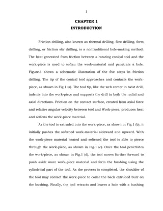
- 1. 1 CHAPTER 1 INTRODUCTION Friction drilling, also known as thermal drilling, flow drilling, form drilling, or friction stir drilling, is a nontraditional hole-making method. The heat generated from friction between a rotating conical tool and the work-piece is used to soften the work-material and penetrate a hole. Figure.1 shows a schematic illustration of the five steps in friction drilling. The tip of the conical tool approaches and contacts the work- piece, as shown in Fig.1 (a). The tool tip, like the web center in twist drill, indents into the work-piece and supports the drill in both the radial and axial directions. Friction on the contact surface, created from axial force and relative angular velocity between tool and Work-piece, produces heat and softens the work-piece material. As the tool is extruded into the work-piece, as shown in Fig.1 (b), it initially pushes the softened work-material sideward and upward. With the work-piece material heated and softened the tool is able to pierce through the work-piece, as shown in Fig.1 (c). Once the tool penetrates the work-piece, as shown in Fig.1 (d), the tool moves further forward to push aside more work-piece material and form the bushing using the cylindrical part of the tool. As the process is completed, the shoulder of the tool may contact the work-piece to collar the back extruded burr on the bushing. Finally, the tool retracts and leaves a hole with a bushing
- 2. 2 on the work-piece as shown in the Fig.1 (e). Friction drilling is a technique to create a bushing on sheet metal, tubing, or thin walled profiles for joining devices in a simple, efficient way. The bushing created in the process is usually two to three times as thick as the original work- piece. This added thickness can be threaded, providing a more solid connection for attachment than attempting to thread the original sheet. Figure 1.1 shows a cross section of the bushing produced for a tapped and untapped hole. All work-material from the hole contributes to form the bushing. In addition, no cutting fluid or lubricant is necessary, which makes friction drilling a totally clean, environmentally friendly process. (a) (b) (c) (d) (e) Figure 1. A schematic illustration of the five steps in friction drilling.
- 3. 3 Figure 1.1. Resulting hole and bushing. 1.2 Applications Potential automotive applications for friction drilling are shown in Fig. 1.2. These include seat frame, exhaust system parts, fuel rail, seat handle, foot pedal, oxygen sensor, and castings. It is believed that the friction drilling technique can be applied on a broader scale in automotive industry. Potential for substitution of a friction drilling fastening process will need to be evaluated on a case-by-case basis. Aluminum and magnesium castings require bolt bosses and thick flanges to accommodate fastening. In hydro formed components, punching holes and attaching weld nuts and clinch nuts are very difficult and/or expensive to accomplish. In certain cases, it appears that sheet metal components are made thicker than necessary for the sole purpose of providing more thread engagement for fasteners. In other cases a threaded hole is needed for attachment of an electrical ground, which requires little load carrying capability.
- 4. 4 Figure 1.2. Automotive applications of friction drilling including (a) seat frame, (b) exhaust O2 sensor boss, (c) exhaust part, (d) seat handle, (e) foot pedal, and (f)oxygen sensor. Advantages • Very quick process. • The process reshapes all material so that no material is lost. The sleeve that is about 3 times longer than the original diameter of the target material makes it possible to make very strong bolt joints in thin material. • Moreover, it is a clean process, because no litter (particles) is produced.
- 5. 5 Disadvantages • The friction drilling process is not possible in massive material. The melting metal must be able to flow somewhere. Yet it is possible to friction drilling holes in subjects up to 12 mm thick. • The target material must be able to withstand the added heat. Materials that have been painted, plastic coated, galvanized, or heat treated are often unsuitable for this process.
- 6. 6 CHAPTER 2 LITERATURE SURVEY The idea of rubbing two materials together to produce heat is as old as people learning to make fire in the stone age. However, applying the principle to drilling holes in metal is a more recent development. Most people who have worked in machine shops have at one time or another tried to drill a hole with a very dull bit. The result is a lot of smoke and heat. Jan Claude de Valliere, working on a little farm in the south of France some seventy-five years ago encountered the same problem. He recognized that if enough heat is generated he could melt and form a hole through the metal. With that thought in mind, he developed a special drill designed to increase friction. After many trials, he found a shape that worked. Jan Claude de Valliere's invention was not at the time commercially or practically viable. Publications on the subject of friction drilling are limited. France et al, Investigates the strength characteristics of friction drilled holes in metal tubing. Overy and Bak discussed the design aspect of the friction drilled holes. Kerkhofs et al, studied the performance of coated friction drilling tools. These publications describe friction drilling tools; equipment needed, and evaluate performance issues of the tool and bushing created. However, past work has approached friction drilling with a “black box” point of view. In depth study of the friction drilling
- 7. 7 process is the purpose of this research. A complete analysis of the friction drilling process was performed for basic understanding of mechanics and details. Friction drilling is similar in concept to friction stir welding (FSW). FSW is a solid state joining process invented in 1991 by The Welding Institute in Cambridge, UK. In this process a rotating tool is used to generate frictional heat and create forging to facilitate continuous solid state joints. The tool consists of a pin, which protrudes from the lower surface of the tool, and the relatively large-diameter shoulder. Welding is initiated by first plunging the pin into the work-pieces until the shoulder is in intimate contact with the component top surfaces. Friction heat is then generated as the shoulder rubs on the top surface under an apparent force. Once sufficient heat is generated and conducted into the work-piece, the tool is propelled forward. Material is softened by the heating action of the shoulder, and transported by the pin across the bond line, facilitating the joint. The only significant difference is that friction drilling heats and softens material to displace it and form a specific shape, while friction stir welding heats and softens material to mix and join it.
- 8. 8 CONCLUSIONS For Al380, the shape and quality of bushing were observed to improve at higher work-piece temperature. Less severe cracking and petal formation were observed on bushings formed at elevated work-piece temperature. This study implies that external heating can be beneficial to increase ductility and improve bushing formation on brittle materials. The high spindle speed did not affect the bushing formation for room temperature Al380. For room temperature MgAZ91D, high spindle speed was detrimental on the bushing shape. The work-piece preheating and high spindle speed was beneficial to reduce the thrust force, torque, energy, and power for friction drilling of brittle cast metals. Higher feed rate and shorter cycle time for hole drilling was feasible with the reduced thrust force and torque. Exploring the surface roughness using the Taguchi methods, a proper geometric shape of drill and parameters of drilling were found in order to obtain a quality hole surface. The optimal drilling condition was A1 (friction angle = 30◦), B1 (friction contacted area ratio = 50%), C2 (feed rate = 100 mm/min), D3 (drilling speed = 90m/min). Then four confirmatory runs were conducted and an average surface roughness value Ra = 0.96µm was obtained. The optimal geometric shape and friction contact area ratio of the friction drill was selected to conduct the experiments. Results showed that Tungsten carbide created a serious
- 9. 9 wear of the drill edge after three runs. However, the friction drill of this study showed little wear and was still able to drill the AISI 304 material after 60 runs. Therefore, the friction drill had a better performance such as avoiding serious tool wears, enhancing hole quality, and prolonging the tool life significantly.
- 10. 10 REFERENCES 1. Kurt lange,”Hand book of Metal forming”, Me Graw-Hill, 1987. 2. Mechanical Behavior of Materials by Thomas H. Courtney. 3. Taguchi Techniques for Quality Engineering by Phillip J.Ross. 4. Sciencedirect.com. 5. Howstuffworks.com.