1. White Paper
Implementing Traffic Managers in Stratix II
Devices
February 2004, ver. 1.0 1
WP-STXIITRFC-1.0
Introduction
Bundling voice, video, and data services provides carriers with a steady revenue stream while reducing
customer turnover. Delivering these services through a common infrastructure reduces a carrier’s
operational expenditures. In addition, “future-proofing” networks with flexible solutions that enable the
delivery of enhanced services down the road enables carriers to limit their long-term capital expenditures.
These factors are the motivation behind the increasing focus on guaranteeing Quality of Service (QoS)
through traffic management.
Altera’s Stratix™
II family continues the trend of using FPGAs for traffic managers because of the inherent
flexibility of FPGAs and because the Stratix II architecture has been optimized for performing traffic
management functions. In addition to the extensive internal memory and I/O pins, the Stratix II device
offers substantial density and performance improvements. These improvements are attributed to both
technology advancements and architectural optimizations.
This white paper discusses traffic management and the implementation of traffic management functions
within Stratix II devices. This white paper also provides an analysis of several of these functions, including
scheduling and queue management, and describes improvements within the Stratix II architecture that
optimize these functions. Additionally, because of the importance of memory management in traffic
management, this paper discusses memory and memory interfacing.
Traffic Management Background
Traffic management enables bandwidth management through the enforcement of service level agreements
(SLAs). SLAs define the criteria a network must meet for a specified design, including:
Guaranteed bandwidth, or throughput, including minimum, average, and peak guarantees of
bandwidth availability.
Packet loss the number or percentage of packets sent but not received, or received in error.
Latency the end-to-end delay of packets.
Jitter the delay variation between consecutive packets.
2. Implementing Traffic Managers in Stratix II Devices Altera Corporation
2
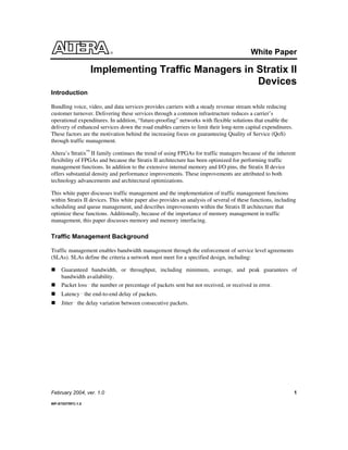
Figure 1 shows a typical line card. The packet processor classifies the ingress data traffic (data traveling
from the line side toward the switch) and determines which port the data should exit. The data header is
also modified by the packet processor, which adds the appropriate class. The traffic manager uses this
header to enforce the Service Level Agreement (SLA) that defines the criteria that must be met for a
specified customer or service. With egress traffic (data traveling from the switch to the line side), the
traffic manager smoothes large spikes in traffic, allowing the overall network to run more efficiently. A
traffic manager in the data path (as shown in Figure 1) is considered to be in “flow-through” mode. An
advantage of this mode is it reduces the complexity of the packet processor by offloading the packet
buffering. A traffic manager outside the data path is considered in “lookaside” mode. In this mode, the
packet processor communicates to the traffic manager through a “lookaside” interface and receives
scheduling information, but the packet processor is also the interface to the backplane transceiver. In this
mode the packet processor buffers the packets, and the traffic manager is responsible for maintaining the
descriptor tables..
Figure 1. A Typical Line Card Block Diagram
Figure 2 shows a block diagram of a generic traffic manager. Not all traffic managers implement all the
functions shown in the figure. Some of the functions in the diagram may also be implemented within the
packet processor.
The data arriving into the traffic manager can be complete variable-length packets or fixed-length cells.
Many traffic managers or packet processors segment packets into fixed-length cells, because switch fabrics
can be optimized for switching those fixed-sized cells. The modified header of incoming data traffic allows
traffic managers to prioritize and decide which packets should be dropped and retransmitted, when packets
should be sent to the switch fabric, and how traffic should be shaped when sending it to the network.
3. Altera Corporation Implementing Traffic Managers in Stratix II Devices
3
Figure 2. Generic Traffic Manager Block Diagram
Computationally Intensive Functions: Scheduling
This section includes details on the implementation of several scheduling functions found in traffic
managers and descriptions of the advantages gained from the Stratix II architecture.
A scheduler has four basic parameters:
The number of priority levels.
The type of service (work-conserving or nonwork conserving).
The degree of aggregation.
The service order within a priority level.
4. Implementing Traffic Managers in Stratix II Devices Altera Corporation
4
If a scheduler supports priorities, it serves a packet from a priority level only if there are no packets waiting
for service in an upper priority level. With such a scheme, connections that require QoS and are intolerant
of delays can be serviced with higher priority than others. A potential problem with a priority scheme is
that a user at a higher priority level may increase the delay and decrease the available bandwidth for
connections at all lower priority levels. An extreme case of this is starvation, where the scheduler never
serves a packet of a lower priority level because there is always something to send from a higher priority
level. In an integrated services network, at least three priority levels are desirable: a high priority level for
urgent messages, usually for network control; a medium priority level for guaranteed service traffic; and a
low priority level for best-effort traffic. The VoQ structure can also be implemented outside the FPGA in
SRAM, because the queue overflow generally occurs in the input stage of the switch . In this case,
scheduling must be fast, and the switch resource is not available.
There are two types of scheduling service: work conserving and nonwork conserving. A work-conserving
scheduler is idle only when there is no packet awaiting service. In contrast, a nonwork-conserving
scheduler is idle even if it has packets to serve so as to shape the outgoing traffic to reduce traffic
burstiness and the delay jitter. The work-conserving discipline is more suitable for best-effort traffic
(Internet Protocol (IP) traffic), and the nonwork-conserving discipline is better applied to guaranteed-
service traffic (voice and video). The new integrated network systems need schedulers that serve both
types of traffic. The flexibility of the Stratix II FPGA architecture allows the implementation of both types
of traffic.
The WRR Algorithm
The weighted round robin (WRR) scheme assigns different priorities to different queues. The selection
policy involves selecting the queues according to their priority and is based on the SLA agreement or type
of traffic. One way to implement this scheme is by maintaining urgency counters for each queue. Each
urgency counter maintains a value that represents the weighting of its queue. This section discusses the
implementation of this algorithm in Stratix II devices.
To perform the selection, the WRR algorithm increments the urgency counters of all the active queues by
their respective weights, or priority. The active queue with the highest value in the urgency counter is
selected, and then this urgency counter is decremented by the sum of all the weights of the active queues.
The algorithm for WRR is
1. Choose all the active queues
2. Update the counters of all the active queues Counti (active) =
Counti (active) + Wi
3. Select the maximum count , Counti (active) max
4. Normalize, Counti (active) max = Counti (active) max -
Wi(active)
Where Counti is the urgency counter value , Wi is the weight and
the index and "i" is the queue.
This paper analyzes in detail step 3, selecting the maximum urgency counter (Max Ci
), because it has the
highest arithmetic complexity. In this example, the entire list of active urgency counters must be sorted and
the maximum urgency counter must be selected.
5. Altera Corporation Implementing Traffic Managers in Stratix II Devices
5
This examples assumes 32 virtual output queues (VOQs) with 4 priority levels each, producing 128
priority queues (32 VOQs x 4 priorities = 128 priority queues). To determine the length of the urgency
counter, the queue ID and queue weights need to be computed. The queue ID for these 128 queues requires
7 bits (log2
128 = 7 bit Qid). In this example, each queue can have a weighting that ranges from 0 to 512,
which requires the queue weights (Qw) to be 9 bits (log2
512= 9 bit Qw). In addition, an extra bit should be
added to the urgency counter to handle negative values. The size of the urgency counter in this example is
9+7+1 bits, or 17-bits wide. Each scheduling decision requires the WRR scheduler to sort and select from
the 128 different 17-bit urgency counters.
There are several implementation possibilities for sorting these urgency counters. This example shows an
array architecture implementation. The array architecture for comparing the urgency counters uses a
128x17 matrix of 2-bit comparators, as shown in Figure 3. The matrix determines the maximum value of
the 128 urgency counters. The horizontal rows in the matrix represent a bit slice of the 17-bit urgency
counters. The vertical columns in the matrix represent the urgency counter values for each of the 128
urgency counters.
Each of the comparators takes three inputs, the urgency counter bit value, the bit slice result, and a disable
signal. The cells in the first row and column are all enabled, allowing each to participate in the comparison.
Once a cell is disabled, the disable signal propagates through the rest of the cells of the urgency counter
(for example, this urgency counter is essentially removed from comparison). The array architecture
performw the comparisons for all 128 bits of a bit slice in parallel, determining the maximum bit of the
enabled queues for that bit slice. Then the next bit slice begins comparison. The maximum urgency counter
is obtained after computing the maximum bit of the enabled queues at each of the 17 bit slices.
6. Implementing Traffic Managers in Stratix II Devices Altera Corporation
6
Figure 3. Array Architecture for Urgency Counter Implementation of WRR
Counter1 CounterN
(0,1)
n(0,1)
disable(0,1)
(0,2)
n(0,2)
disable(0,2)
(0,N)
n(0,N)
disable(0,n)
Bit0
M(0)
M(0,1)
M(0,N)
k-1,0
n(0,1)
disbl(k-1,1)
k-1,1
n(0,2)
dis(k-1,2)
k-1,N
n(0,N)
disbl(k-1,n)
Bitk-1
Mk-1
M(k-1,1)
M(0,N)
k-2,0
n(0,1)
dible(k-2,1)
k-2,1
n(0,2)
disbl(k-2,2)
k-2,N
n(0,N)
disbl(k-2,n)
Bitk-2
Mk-2
M(k-2,1)
M(0,N)
Counter2
As shown in Figure 3, the large number of comparators are essentially three-input functions. Designers can
configure the Stratix II adaptive logic module (ALM) to implement two look-up tables (LUTs) with the
same or different number of inputs. For example, when implementing a function of three or less variables
in a traditional four-input LUT structure, the unused portion of the LUT is wasted. For Stratix II devices,
the unused portion of the LUT can be reused, allowing the implementation of a separate function that has
up to five independent inputs. See Figure 4. This provides greater efficiency by allowing the combination
of comparator functions with other functions within the same LUT.
7. Altera Corporation Implementing Traffic Managers in Stratix II Devices
7
Figure 4. Stratix II Device LUT Packing
In addition, the Stratix II architecture is optimized for wider fan-in functions. For example, designers can
implement the 128 input AND gates required in the array architecture in 27 Stratix II LEs with three levels
of logic, as opposed to 53 LEs with four levels of logic using purely four-input LUTs.
The WRR algorithm described also requires computation of the sum of all the individual weights. For
example, this can be done by using a pipelined arithmetic addition scheme that uses the Wi
’s and the queue
activity status to calculate the ΣWi
(active). In the example, for N=128 with a 16 stage pipeline, each adder
must add eight weights that are 9-bits wide. The Stratix II architecture reduces the logic resources and
summation stages by allowing the usage of three input adders inside an ALM (see Figure 5).
Figure 5. Three-Input Adder Implementation
8. Implementing Traffic Managers in Stratix II Devices Altera Corporation
8
The Memory Bottleneck: External Memory
While communication link speeds have grown in 4x increments approximately every two years, memory
performance has only increased 10% per year. This has led to memory becoming a critical bottleneck in
communication systems. Current traffic managers require large amounts of embedded memory as well as
support for high-speed external memory sources.
The amount of external memory required is application dependent, but there are a few general guidelines.
Because data is written into and read out of memory, memory throughput must be at least two times the
line rate. If header information is added to data as it is processed, the throughput requirements increase up
to four times the line rate. The total size of memory in many cases is bounded by the round trip time (RTT)
of the transmission control protocol (TCP). This is the average round trip time between active hosts, and it
can range from 200-300 ms. For example, a 10 Gbps (Gigabits per second) interface requires two to three
Gbits of memory.
In many cases, a segmentation and reassembly (SAR) function is used to segment variable-length packets
into fixed-length cells. Also, switch fabric performance is improved when switching is done with fixed-
length cells. Assuming the switch fabric supports a fixed 64 bytes, the calculation for cells to process for
an OC-192 stream is
[10 x 109
bits per second] / [64 x 8 bits per Cell] = 19,531,250 cells per second.
Traffic management applications use different external memory. Table 1 compares different external
memories.
Table 1. External Memory Comparison
DRAM SRAM CAM
Latency High Low Very Low
Density High Low Low
Cost Low High Very High
Power Low Medium Very High
Applications Packet Buffer
Pointers, Flow
Tables, Rate Tables
Search, Classification
SDRAM is inexpensive and has high bandwidth but also higher latency compared to SRAM, so it is used
for functions with very high density needs. SDRAM buffers the data as it is being processed. SDRAM also
requires many pins. The example shown in Figure 6 shows the number of pins required to interface to a 64-
bit SDRAM. Many types of high-end networking equipment require several of these devices, leading to
very high pin requirements for traffic management devices.
9. Altera Corporation Implementing Traffic Managers in Stratix II Devices
9
Figure 6. SDRAM Pin Example
Part Description
Pin Name Function Total Pins
A[0-12] Address bits 13
BA[0-1] Bank Address 2
DQ[0-63] Data In/Out 64
DQS[0-7] Data Strobe 8
CK[0-2] Clock 3
!CK[0-2] !Clock 3
CKE[0-1] Clock Enable 2
CS[0-1] Chip Select 2
RAS Row Address 1
CAS Column Address 1
WE Write Enable 1
DM[0-7] Data - in mask 8
Total Pins 108
64-bitx128Mb
Stratix II FPGAs are available in advanced pin packages that provide board area savings as well as high
pin counts. For example, the Stratix II device is offered in the 1,508-pin Fineline BGA package with up to
1,150 user I/O pins. These high pin counts provide easy access to I/O pins for implementing with external
memory chips and other support devices in the system.
External Memory Bandwidth Analysis Example
When determining the appropriate memory requirements for buffering packets both the width and depth of
the memory should be considered (see Figure 7).
Figure 7. Width & Depth of the Memory Subsystem
The required width is dependent on the memory’s throughput. For example, if a 32-bit wide memory
device (data) has an access time of 20 ns (50 MHz), the throughput in terms of raw bits from this device is
32 x 50 x 106
bits per second, that is, 1.6 Gbps. It takes two cycles to access each 32-bit data word, one
cycle for the read_enable signal or the write_enable signal, and one cycle for the address latching. On the
third cycle one access reads a 32-bit data word. The overhead for each 32-bit word read/write for this
device is 40 ns. The total read or write cycle takes 60 ns, so the effective throughput from this device is 32
x 1/60 x 109
bits per second = 534 Mbps. Figure 8 shows this in the sample timing diagram.
MEMORY SUBSYSTEM
Depth = K words
Width = N words
10. Implementing Traffic Managers in Stratix II Devices Altera Corporation
10
Figure 8. Memory Timing Diagram Sample
The timing diagram in Figure 8 shows that it takes a maximum time equal to tRC + tHCZE to read a data
word from the port of this memory device. In burst access situations where more than one word is read
from or written to memory, the timing overhead is reduced for control signals such as CE (chip enables)
and read_enable or write_enable. However, there is a limitation in burst reads and writes. Consider the
addresses from which data is accessed. Typically, in a four-word burst, data is accessed from addressN
(base address), addressN+1
(base address + 1 word offset), addressN+2
(base address + 2 word offset),
addressN+3
(base address + 3 word offset), and so on.
The memory depth requirements are driven by the processing time required to forward each packet after
performing scheduling and the output time for traffic.
Estimate the depth of the memory and other characteristics with a combination of the following:
The arrival rate of each bit or word into the memory.
The departure rate of each bit or word out of memory.
If the word size for a memory subsystem is 16 bytes, the arrival rate is = 128/10 ns = 12.8 ns or .1 ns per
bit for a 10Gbps card. Similarly, if the processing time for the scheduler and the traffic manager is 1
microsecond, the bit that arrived must be buffered for 1000 ns or there must be a buffer large enough to
store 10,000 bits without dropping them from the ingress portion of the flow.
For sizing purposes the following applies:
Width of the memory subsystem = Packet Throughput / Frequency of operation
# of devices required of the given frequency :
Width of memory sub system / Data word width per device of the same frequency
11. Altera Corporation Implementing Traffic Managers in Stratix II Devices
11
Memory requirements are simplified for this example by assuming a 4x bandwidth increase in the line rate.
This increase includes the read and write cycles as well as other latencies associated with burst accesses.
The chart shows the required memory throughput for different line rates and memory bus widths.
Memory Bus Width
32-bit 64-bit 128-bit 256-bit 512-bit
OC-12 78 Mbps 39 Mbps 19 Mbps 10 Mbps 5 Mbps
OC-48 313 Mbps 156 Mbps 78 Mbps 39 Mbps 20 MbpsLine Rate
OC-192 1250 Mbps 625 Mbps 313 Mbps 156 Mbps 78 Mbps
Stratix II devices deliver memory throughput requirements for high bandwidth applications by supporting
advanced memory technologies, which are shown in Table 2.
Table 2. Stratix II External Memory Interface Support
Memory Technology I/O Std Max. Clock Max Data Rate
SDR SDRAM LVTTL 200 MHz 200 Mbps
DDR SDRAM SSTL 200 MHz 400 Mbps
DDR II SDRAM SSTL 1.8V I, II 266 MHz 533 Mbps
QDR II HSTL I, II 250 MHz 500 Mbps
RLDRAM-II HSTL I, II 300 MHz 600 Mbps
The Memory Bottleneck: Queue Manager
A queue manager buffers the incoming data traffic from the packet processor and creates tables of pointers
to the buffered data. These buffers typically are located off-chip in external memory, but with embedded
memories, portions of the queue manager buffers can be kept on-chip. This section discusses an
implementation of a queue manager utilizing the internal memory blocks of Stratix II devices.
Internal Memory in Stratix II Devices
The use of internal SRAM reduces pins, power, board space, cost, and latency. Stratix II devices provide
embedded TriMatrix™
memory that is capable of handling the traffic management memory requirements.
For example, Stratix II devices offer up to 9 Mbits of memory. The TriMatrix memory consists of three
types of memory blocks, M512, M4K, and M-RAM. The M512 block supports 512 bits of memory, the
M4K block supports 4Kbits, and the M-RAM block supports up to 512 Kbits of memory per block.
Queue Manager
To implement the queue manager, map the internal M-RAM memory to the external memory. This address
mapping can be done dynamically by creating a linked list structure in hardware. Or, memory can be
allocated statically by dividing the external memory into fixed sized submemory blocks. There are
advantages and disadvantages to both approaches. The dynamic approach is more flexible and allows for a
better utilization of memory, while the static approach does not incur the overhead of a linked-list structure
and allows simpler handling of status signals. The information in this section describes the static memory
allocation approach only. Refer to Figure 9 for an example of a statically allocated memory
implementation.
12. Implementing Traffic Managers in Stratix II Devices Altera Corporation
12
Figure 9. Static Memory Allocation
Memory Address
Pointers Stored
in M-RAM
Data Stored in External
RAM
Each queue/flow has a single entry, referred to as the queue entry, in the M-RAM. The following
information describes the queue:
Status flags Head pointer (read) Tail pointer (write)
The status flags contain empty, full, almost empty, and almost full flags for each queue/flow. The head
pointer stores the address location for the next read for the queue/flow in the external memory. The tail
pointer stores the address location for the next write for the queue/flow in the external memory. Depending
on the depth of the queue/flow required, the external memory is segmented into submemory blocks, which
are controlled by each entry in the M-RAM, representing a single queue/FIFO.
For example, with an address width of 25-bits, designers can configure the M-RAM in 8k x 64-bit wide
mode. The 64-bits would contain two 25-bit addresses and additional status flag bits. This configuration
can manage up to eight thousand queues/flows. Merging multiple M-RAMs builds larger queue managers.
The depth of the queues/flows are determined by the size of the external memory.
13. Altera Corporation Implementing Traffic Managers in Stratix II Devices
13
The following information provides an example of a read or write process to the multi-queue/flow FIFO.
The requirements for the example are
64 queues/flows
Frame size of 64 bytes
Queue/flow depth of 128 frames
The requirements shown in the list require each queue to be 8,192 bytes, and the entire memory to be
524,288 bytes, or 4 Mb. Memory is allocated to the first queue from 0-8,191 bytes, to the second queue
from 8,192-16,384 bytes, and so on. When the pointers reach the upper limit of the allocated memory
section, they loop back to the lower limit. The M-RAM is configured in the 8k x 64 mode to store a 64-bit
wide queue entry.
Read & Write Operations
When a packet arrives at the queue, the scheduler determines which queue the packet is to be stored in, for
example, queue 0-63. If a write to queue three is requested, the M-RAM accesses the queue entry at
address location three. After the first clock cycle, the tail pointer is masked and sent to the external
memory controller, along with the frame to be stored. The tail pointer is incremented by one frame size and
operations are performed on the head and tail pointers to update the status flags. The updated pointers and
status flag bits are written back into the M-RAM on the second cycle. The same occurs for a read request.
Therefore, read and write requests take two cycles in the M-RAM, one cycle to obtain the external address
to read or write from and one to update the pointers and status flags. The updated status flag bits for queue
three are also sent to the queue manager for processing.
Status-signal generation and processing occurs immediately after a read (see Figure 10) or write (see
Figure 11) request because status signals are embedded in the queue entry. (The alternative is to register
individual status signals for each queue, which is not efficient. For example, empty and full flags with
8,000 queues would require 16k registers.) After signal generation and processing, the next step is to
subtract the head pointer from the tail pointer and compute the absolute value. If the difference is zero, the
queue is empty. If the difference is equal to the maximum depth of the queue, the queue is full. The queue
manager must control the pointers so that the head (read) pointer never leads the tail (write) pointer and
manage the queues when they become full and empty. If the queue is empty, the queue manager should
ignore all reads from the external memory for that queue. Other intermediate status signals such as almost
full and almost empty flags may be generated as well.
14. Implementing Traffic Managers in Stratix II Devices Altera Corporation
14
Figure 10. Read Operation
Address
Counter
Status
Flags
Memory
Controller
External Memory
M-RAMPolicer/
Scheduler
Queue Address
Wr/Rd
Data
Frame
Queue Entry
Address
Data
1
2
3
4
5
6
8
7
Read Request
Wr/Rd
1. Read request to the scheduler or from within the scheduler.
2. Scheduler sends the appropriate queue address to read from the M-RAM.
3. The status flag is masked out and the head pointer is sent to the memory controller
4. Calculate appropriate status flags for the queue with pointer information.
5. Check the status flags to determine if immediate action is required, for example, the queue is empty,
and so on. If the queue is empty, a read from external memory is not required.
6. Send the head pointer to the address counter to increment to the next memory location.
7. Rebuild the queue entry and write the data into M-RAM.
15. Altera Corporation Implementing Traffic Managers in Stratix II Devices
15
Figure 11. Write Operation
Address
Counter
Status
Flags
Memory
Controller
External Memory
M-RAMPolicer/
Scheduler
Queue Address
Wr/Rd
Data
Frame
Queue Entry
Header
Address
Data
Incoming Data
1
2
3
4
9
5
6
8
7
Wr/Rd
1. Incoming data from traffic. Mask out the header to the scheduler and the frame to memory
controller.
2. The scheduler parses the header information and determines in which queue to place the frame.
3. Send a read request to M-RAM and the queue address to access.
4. Mask out the tail pointer that contains the address in the external memory and send the tail pointer
to the memory controller.
5. Send the tail pointer to the address counter to increment to the next memory location.
6. Calculate appropriate status flags for the queue with pointer information.
7. Check status flags to determine if immediate action is required, for example, the queue is full, and
so on.
8. Rebuild the queue entry and write the data into M-RAM.
16. Implementing Traffic Managers in Stratix II Devices Altera Corporation
16
Static Memory Allocation
For statically allocated memory, initialize the M-RAM with the submemory block starting addresses for
each queue before startup. The M-RAM requires an initialization circuit to write the starting addresses for
each queue/flow. This can be done using a state machine and a counter that increments by the depth of
each queue/flow. Once the M-RAM has been initialized, the state machine sends a flag to the queue
manager confirming that it is ready to operate as queue manager. Alternatively, use an external LUT to
initialize the M-RAM. The external LUT has the starting address for each queue, which is read into the M-
RAM to initialize the queue manager.
To determine the memory space for each queue (see Table 3), allocate memory space of 2x
for each queue,
where the memory space is divisible by the frame size. This simplifies the pointer address operations,
because the counter increments by the frame size, and when it reaches the upper memory space limit, it
automatically rolls over to zero or the lower limit. For example, if the frame size is 64 bytes (26
) and the
depth is 128 frames, each memory space is 8,192 bytes (213
). The address can then be broken up into two
parts, the static MSB portion that denotes which queue it belongs to and a dynamic LSB portion that
changes as the specific queue is filled.
Table 3. Pointer Address Example
Static Queue Identifier Dynamic Frame Counter/Pointer for Queue
000000000000 0000000000000
000000000001 0000000000000
… …
… …
111111111110 0000000000000
111111111111 0000000000000
The upper MSB bits remain the same for a specific queue; only the lower LSB bits change by the address
counter. This keeps the address counter operation small and uniform for all queues, and more efficient.
The alternative is to have a special function handle the pointers for each queue once it reached its upper
limit. For example, you can implement some sort of look up in logic, outside of the functions described, to
reset the pointer to the lower limit. For example, implement a look-up function in logic (outside of the
functions described) to reset the pointer to the lower limit.
Traffic Shaping
Traffic shaping is a mechanism that alters the traffic characteristics of a stream of packets/cells in order to
make them conform to a traffic descriptor. A traffic descriptor is a set of parameters that describes the
behavior of a data source. There are three parameters that describe the data source traffic:
The average rate
The peak rate
The burst size
Shaping the data source traffic to the above parameters means that the data source can send packets at the
long-term average rate or it can send bursts at the peak rate. Traffic shaping is performed at the entrance
nodes of the network, and the devices that shape the incoming traffic are called regulators.
17. Altera Corporation Implementing Traffic Managers in Stratix II Devices
17
Leaky Bucket Algorithm
The leaky bucket algorithm accumulates fixed-size tokens into a bucket at a defined rate. An incoming
packet is transmitted only if the bucket has enough tokens. Otherwise, the packet waits in a buffer until the
bucket has enough tokens for the length of the packet. Figure 12 illustrates the leaky bucket operation. As
the figure shows, tokens are added to the bucket at the average rate. On a packet departure, the leaky
bucket removes the appropriate number of tokens. If the incoming packets are segmented into fixed-size
units and one token is removed from the bucket for a packet departure, then the size of the bucket
corresponds to burst size.
By replenishing tokens in the bucket at the average rate and permitting the departure of contiguous packets
one can control two of the three traffic parameters: average rate and burst size. To control the peak rate,
add a second leaky bucket. If the token replenishment interval corresponds to the peak rate, and the token
bucket size is set to one token, the second leaky bucket is a peak-rate regulator. The second leaky bucket is
located before the first leaky bucket and is used to insert traffic that is conforming to peak rate. The second
leaky bucket does not have a buffer. Instead of dropping the nonconformant packets it marks them and
transmits them to the next leaky bucket. The marked packets are dropped in case of buffer overflow. If the
next leaky bucket does not have a buffer to keep the nonconforming packets, it is called a policer. A
policer drops the nonconforming or marked packets. A leaky bucket can be implemented as a calendar
queue (a standard implementation) or a slotted wheel. The next section describes an example of a calendar
queue.
Figure 12. Simple Leaky Bucket Model
Calendar Queue Implementation of Leaky Bucket
A calendar queue consists of a clock and an array of pointers, as shown in Figure 13. Each pointer
corresponds to the list of packets that are serviced during this slot. The “initial” duration of a slot equals the
calendar queue’s clock period. However, due to the variability in the number of the packets in each list, the
time slot duration is variable. When all the packets of a slot’s list are serviced, the next slot becomes active.
The pointer of the next slot indexes to its corresponding list of packets. A packet is inserted into the proper
slot after the scheduler assigns a slot tag to it. A packet that must be serviced during a slot in the current
round may be linked in the same list with a packet that must be serviced at the next round. The calendar
queue size is estimated as follows:
# of slots x calendar queue clock period > period of slowest connection
Arriving 64 Byte Cells
Token Pool
Departing 64 Byte Cells
Token Generator
18. Implementing Traffic Managers in Stratix II Devices Altera Corporation
18
This algorithm is implemented using the Stratix II MRAMs, following a structure similar to that described
in the section “The Memory Bottleneck: Queue Manager.” The memory structures of Stratix II devices
enable the shapter to maintain the list of pointers inside the device, eliminating the off-chip delays and
additional board space associated with external memories.
Figure 13. Simple Calendar Queue Mode
Statistics
Also called metering, statistics provide information on whether packets do not meet appropriate SLAs.
You can also use metering to enable dynamic billing based on usage.
High-speed counters perform traffic management metering at high speeds, and the results of these counters
are stored in memory. A hierarchical memory structure supports the large number of counters necessary for
keeping statistics. Figure 14 shows an example of this type of memory.
You can implement the high-speed counters in the Stratix II logic elements. Such counters are capable of
running at speeds of more than 300 MHz.
Calendar Days
1
2
3
N
A B C D
FE
Tasks
19. Altera Corporation Implementing Traffic Managers in Stratix II Devices
19
Another way to use internal memory is to create a hierarchical memory structure to support statistics
counters. The need for hierarchical memory again arises from the external DRAM memory bottleneck. The
throughput of current DRAM technologies cannot meet the requirements of updating numerous counters
per cell at line rate due to the inherent latency of DRAM. This inherent latency requires temporary counters
to be stored in SRAM; they are then used to update the external DRAM occasionally. In this case, the
DRAM latency is only incurred periodically, and is determined by the size of the SRAM counters. The
statistics engine updates the appropriate “small” counter values in SRAM as packets are received.
Periodically, the statistics engine then reads the “large” counter values from external DRAM and adds the
“small” counter values. Then it resets the “small” counter value to zero in the internal SRAM. The M4K
blocks within Stratix II devices can be configured to temporarily store the count values for each counter.
For example, for 64K flows, the M4K blocks can store up to three 8-bit counters for each flow. This
reduces the number of times the external DRAM needs to be accessed by up to 28
.
Figure 14. Hierarchical Memory for Statistics Engines
20. Implementing Traffic Managers in Stratix II Devices Altera Corporation
20
Conclusion
In today’s environment, ASIC or standard product solutions incur a significant amount of risk. Volumes
are uncertain, which leads to exorbitant nonrecurring engineering (NRE) costs, as well as a limited number
of ASSP providers that the market can support. FPGAs are a natural fit for implementing traffic managers
because of the limitation of this risk and the ability to differentiate a traffic management solution.
Additionally, you can use a reconfigurable solution to add and support new services in the future.
The advanced architecture of Stratix II devices coupled with the advantages of 90nm process technology
migration enable the devices to service high-end traffic manager requirements. The enhanced fabric is
optimized for the computationally intensive functions of traffic management. The support of flexible high-
speed memory allows memory management at today’s highest rates, with support for future memory
standards. The embedded memory structure of Stratix II devices enables storage of pointer tables into the
large M-RAM blocks and statistic caches in M4K blocks. Stratix II devices offer a complete solution for
implementing high-speed traffic management solutions.
21. Altera Corporation Implementing Traffic Managers in Stratix II Devices
21
References
[1] “Maintaining Statistics Counters in Router Line Cards”, Devavrat Shah, Sundar Iyer, Balaji
Prabhakar, Nick McKeown. 2002 IEEE.
[2] “Efficient Per-Flow Queuing in DRAM at OC-192 Line Rate using Out-Of-Order Execution
Techniques”, Aristides Nikologiannis and Manolis Katevenis.
[3] ATM Forum, “Traffic Management Specification Version 4,” Feb 1995.
[4] G. Kavipurapu, M. Nourani, “Switch Fabric Design and Performance Evaluation: Metrics and
Pitfalls,” 46th
MWSCAS, 2002.
[5] G. Kavipurapu, R. Gadiraju, M. Nourani, “System Requirements for Super Terabit Routing,” 45th
MWSCAS, 2001.
[6] C. Labovitz, G. Malan, and F. Jahanian, “Internet routing instability,” IEEE/ACM Transactions on
Networking, vol. 6, p.515-28, Oct. 1998.
[7] V. Paxson, “End-to-end routing behavior in the Internet,” IEEE/ACM Transactions on
Networking, vol. 6, p.601-15, Oct. 1997.
[8] D. Aldous and J. Fill: Reversible Markov Chains and Random Walks on Graphs. Unpublished
manuscript. http://stat- www.berkeley.edu/users/aldous/book.html (1999).
[9] M. Adler and C. Scheideler: Efficient Communication Strategies for Ad-Hoc Wireless Networks.
In Proc. 10th Annual Symposium on Parallel Algorithms and Architectures (SPAA’98) (1998).
[10] J. Broch, D. B. Johnson, and D. A. Maltz: The dynamic source routing protocol for mobile ad hoc
networks. IETF, Internet Draft, draft-ietf-manet-dsr-01.txt, Dec. 1998. (1998).
[11] I. Chatzigiannakis, S. Nikoletseas, and P. Spirakis: Analysis and Experimental Evaluation of an
Innovative and Efficient Routing Approach for Ad Hoc Mobile Networks. In Proc. 4th Annual
Workshop on Algorithmic Engineering, Sep. 2000. (WAE’00)(2000). Also see full paper at
http://helios.cti.gr/adhoc/routing.html
[12] S. Ross, “Applied Probability Models with Optimization Applications,” Dover 1970.
[13] Padhye, Firou et. al, “Modeling TCP throughput: A simple model and its empirical Validation,”
ACM SIGCOMM 1998.
[14] “Router Mechanisms to Support End-to-End Congestion Control”, Technical report,
ftp://ftp.ee.lbl.gov/papers/collapse.ps.
[15] N.Shacham, “Multipoint communication by hierarchically encoded data”, Proc. of IEEE
Infocom’92, (1992), pp.2107-2114.
22. Implementing Traffic Managers in Stratix II Devices Altera Corporation
22
[16] L.Vicisano, L.Rizzo, J.Crowcroft, “TCP-like congestion control for layered multicast data
transfer”, Research Note RN/97/67, UCL, July 1997.
http://www.cs.ucl.ac.uk/staff/L.Vicisano/rlc.ps .
[17] S. Jacobs and A. Eleftheriadis. Providing Video Services over Networks without Quality of
Service Guarantees. In World Wide Web Consortium Workshop on Real-Time Multimedia and the
Web, 1996.
[18] V. Jacobson. Congestion Avoidance and Control. SIGCOMM Symposium on Communications
Architectures and Protocols, pages 314–329, 1988. An updated version is available via
ftp://ftp.ee.lbl.gov/papers/congavoid.ps.Z.
[19] R. Jain. The Art of Computer Systems Performance Analysis. John Wiley and Sons, 1991.
[20] I. Rhee, V. Ozdemir, and Y. Yi. TEAR: TCP Emulation at Receivers – Flow Control for
Multimedia Streaming, Apr. 2000. NCSU Technical Report.
[21] G Kavipurapu, Y. Ragi, A. Chandra, Y. Ragi, “A low cost multi-threaded approach to a SIMD
router simulator.” Also available at http://www.iris-technologies.net/docs/irishipc.pdf
[22] George Kornarosy, Christoforos Kozyrakisz, Panagiota Vatsolakiy, and Manolis Katevenis,
“Pipelined Multi-Queue Management in a VLSI ATM Switch Chip with Credit Based Flow-
Control,” Proc. of 17th Conf. on Advanced Research in VLSI (ARVLSI’97), Univ. of Michigan,
Ann Arbor, USA, Sep. 1997
[23] Christoforos E. Kozyrakis , “The Architecture, Operation and Design of the Queue Management
Block in the ATLAS I ATM Switch,” Institute of Computer Science (ICS), Foundation for
Research and Technology – Hellas (FORTH) TR-172, July 1996.
[24] Balaji Prabhakar Nick McKeown and Ritesh Ahuja, “Multicast Scheduling for Input-Queued
Switches,” IEEE JSAC, May 1996.
[25] Sundar Iyer, Nick McKeown, “Making Parallel Packet Switches Practical,” Infocomm 2001
[26] S. Q. Zheng y, Mei Yang y, and Francesco Masettiz, “Hardware Scheduling in High-Speed, High-
Capacity IP Routers.”
[27] Nikos Chrysos , “Design Issues of Variable-Packet-Size, Multiple-Priority Buffered Crossbars.”
FORTH-ICS /TR-325 October 2003.
[28] Aggelos Ioannou_ and Manolis Katevenis, “Pipelined Heap (Priority Queue) Management for
Advanced Scheduling in High-Speed Networks,” ICC 2001.
[29] Georgios Passas, Performance Evaluation of Variable Packet Size Buffered Crossbar Switches”
FORTH-ICS /TR-328 November 2003
[30] J. Blanton, H. Badt, G. Damm, and P. Golla, “Iterative scheduling algorithms for optical packet
switches”, ICC 2001 Workshop, Helsinki, June 2001.
23. Altera Corporation Implementing Traffic Managers in Stratix II Devices
23
[31] G. Damm, J. Blanton, P. Golla, D. Verchere, and M. Yang, “Fast scheduler solutions to the
problems of priorities for polarized data traffic” Proc. of International Symposium on
Telecommunications (IST’01), Tehran, Iran, Sept. 2001.
[32] M. J. Karol, M. G. Hluchyj and S. P. Morgan, “Input vs. output queuing on a space-division
packet switch”, IEEE Transaction on Communications, Vol. 35, No. 12, pp. 1347-1356, 1987.
[33] W. J. Cook,W. R. Pulleyblank, A. S., and W. H. Cunningham, Combinatorial Optimization,
Wiley John & Sons Inc., Nov.1997.