
Recommended
More Related Content
Similar to Knee joint (Radiographic projection's)
Similar to Knee joint (Radiographic projection's) (20)
Recently uploaded
Recently uploaded (20)
Knee joint (Radiographic projection's)
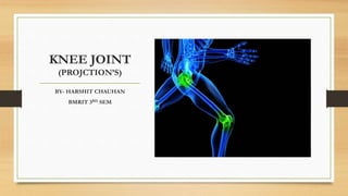
- 1. KNEE JOINT (PROJCTION’S) BY- HARSHIT CHAUHAN BMRIT 3RD SEM
- 3. VIEWS OF KNEE JOINT ROUTINE • AP view • Lateral view • Oblique view SPECIAL • AP bilateral weight-bearing • PA axial bilateral weight-bearing (ROSENBERG METHOD)
- 4. AP PROJECTION : KNEE JOINT Clinical Indications • Fractures lesions • Bony changes related to degenerative joint disease • Forigen body localization Technical Factors • Minimum SID—40 inches (102 cm) • IR size—24 × 30 (10 × 12 inches), portrait • Analog—65 to 75 kV range , mAs —7 - 10 • Digital systems—75 ± 5 kV range , mAs —7 – 10 Shielding Shield radiosensitive tissues outside region of interest. AP knee—CR perpendicular to IR
- 5. Patient Position • Place patient in supine position with no rotation of pelvis • Provide pillow for patient’s head • Leg should be fully extended. Part Position • Align and center leg and knee to CR and to midline of table or IR.. • Rotate leg internally 3° to 5° for true AP knee (or until interepicondylar line is parallel to plane of IR). • Place sandbags by foot and ankle to stabilize if needed. AP knee
- 6. CR • Align CR parallel to articular facets (tibial plateau); for average-size patient, CR is perpendicular to IR • Direct CR to a point 1 2 inch (1.25 cm) distal to apex of patella. Recommended Collimation Collimate on both sides to skin margins at ends to IR borders. AP knee
- 7. AP OBLIQUE PROJECTION— MEDIAL (INTERNAL) ROTATION: KNEE Clinical Indications • Pathology involving the proximal tibiofibular and femorotibial (knee) joint articulations • Fractures, lesions, and bony changes related to degenerative joint disease, especially on the anterior and medial or posterior and lateral portions of knee Technical Factors • Minimum SID—40 inches (102 cm) • IR size—24 × 30 cm (10 × 12 inches), portrait • Grid or bucky, >10 cm • Nongrid, tabletop, • Analog—65 to 75 kV range • Digital systems—75 ± 5 kV range AP medial oblique.
- 8. Shielding Shield radiosensitive tissues outside region of interest. Patient Position • Place patient in semisupine position, with entire body and leg rotated partially away from side of interest • Place support under elevated hip • Give pillow for head. Part Position • Align and center leg and knee to CR and to midline of table or IR. • Rotate entire leg externally 45° (intereepicondylar line should be 45° to plane of IR) • If needed, stabilize foot and ankle in this position with sandbags. AP medial oblique
- 9. CR Angle CR 0° on average patient distal to apex of patella. Recommended Collimation Collimate on both sides to skin margins, with full collimation at ends to IR borders to include maximum femur and tibia- fibula. AP medial oblique
- 10. AP OBLIQUE P ROJECTION—LATERAL (EXTERNAL) ROTATION: KNEE Clinical Indications • Pathology involving femorotibial (knee) articulation • Fractures • lesions, and bony changes related to degenerative joint disease, Technical Factors • Minimum SID—40 inches (102 cm) • IR size—24 × 30 cm (10 × 12 inches), portrait/ grid or bucky, >10 cm • Nongrid, tabletop, • Analog systems—65 to 75 kV range • Digital systems—75 ± 5 kV range AP lateral oblique.
- 11. Shielding Shield radiosensitive tissues outside region of interest. Patient Position • Place patient in semisupine position, with entire body and leg rotated partially away from side of interest • Place support under elevated hip • Give pillow for head. Part Position • Align and center leg and knee to CR and to midline of table or IR. • Rotate entire leg externally 45° (interepicondylar line should be 45° to plane of IR) • If needed, stabilize foot and ankle in this position with sandbags. AP lateral oblique.
- 12. CR • Angle CR 0° on average patient • Direct CR to midpoint of knee at a level 1 2 inch (1.25 cm) distal to apex of patella Recommended Collimation Collimate on both sides to skin margins, with full collimation at ends to IR borders to include maximum femur and tibia- fibula. AP lateral oblique
- 13. LATERAL—MEDIOLATERAL PROJECTION: KNEE Clinical Indications • Fractures • Lesions, and joint space abnormalities Technical Factors • Minimum SID—40 inches (102 cm) • IR size—18 × 24 cm (8 × 10 inches) or 24 × 30 cm (10 × 12 inches), portrait • Grid or bucky, >10 cm • Nongrid, tabletop Shielding Shield radiosensitive tissues outside region of interest Mediolateral knee
- 14. Patient Position • This position may be taken as a horizontal beam lateral or in the lateral recumbent position • Lateral Recumbent Projection This projection is designed for patients who are able to ex the knee 20° to 30°. • Take radiograph with patient in lateral recumbent position, affected side down • Provide pillow for patient’s head • Use a horizontal beam with IR placed beside knee • Place support under knee to avoid obscuring posterior soft tissue structures . Mediolateral knee
- 15. Part Position • Adjust rotation of body and leg until knee is in true lateral position (femoral epicondyles directly superimposed and plane of patella perpendicular to plane of IR). • Flex knee 20° to 30° for lateral recumbent projection. • Align and center leg and knee to CR and to midline of table or IR. CR • Angle CR 5° to 7° cephalad for lateral recumbent projection • Direct CR to a point 1 inch (2.5 cm) distal to medial epicondyle Mediolateral knee
- 16. SPECIAL • AP bilateral weight-bearing • PA axial bilateral weight-bearing (ROSENBERG METHOD)
- 17. AP WEIGHT-BEARING BILATERAL KNEE PROJECTION: KNEE Clinical Indications • Femorotibial joint spaces of the knees • Forigen body localization • Dislocation Technical Factors • Minimum SID—40 inches (102 cm) • IR size—35 × 43 cm (14 × 17 inches), landscape • Grid • Analog—70 ± 5 kV range • Digital systems—75 ± 5 kV range Shielding Shield radiosensitive tissues outside region of interest AP bilateral weight-bearing
- 18. Patient and Part Position • Position patient erect and standing on attached step or on step stool to place patient high enough for horizontal beam x-ray tube. • Position feet straight ahead with weight evenly distributed on both feet; provide support handles for patient stability. • Align and center bilateral legs and knees to CR and to midline of table and IR; IR height is adjusted to CR CR • CR perpendicular to IR (average-sized patient), or 5° to 10° caudad on thin patient, directed to midpoint between knee joints at a level 1 2 inch (1.25 cm) below apex of patellae. Recommended Collimation Collimate to bilateral knee joint region, including some distal femurs and proximal tibia for alignment purposes AP bilateral weight-bearing
- 19. PAAXIAL WEIGHT-BEARING BILATERAL KNEE PROJECTION: KNEE (ROSENBERG METHOD) Clinical Indications • Femorotibial joint spaces of the knees demonstrated • Knee joint spaces and intercondylar fossa demonstrated Technical Factors • Minimum SID—40 inches (102 cm) • IR size—35 × 43 cm (14 × 17 inches), landscape • Grid • Analog—70 ± 5 kV range • Digital systems—75 ± 5 kV range Shielding Shield radiosensitive tissues outside region of interest.
- 20. Patient and Part Position • Position patient erect, standing on attached step of x-ray table or on step stool if the upright bucky is used so that patient is placed high enough for 10° caudad angle. • Position feet straight ahead with weight evenly distributed on both feet and knees flexed to 45°; have patient use bucky device for support, with patella touching the upright bucky • Align and center bilateral legs and knees to CR and to midline of upright bucky and IR; IR height is adjusted to CR. CR • CR angled 10° caudad and centered directly to midpoint between knee joints at level 1 2 inch (1.25 cm) below apex of patellae when a bilateral study is performed Rosenberg method—bilateral PA axial projection
- 21. Recommended Collimation Collimate to bilateral knee joint region, including some distal femurs and proximal tibia for alignment purposes. Normal bilateral knee radiograph performed using the Rosenberg method. Both medial and lateral compartments show no significant narrowing. Abnormal bilateral knee radiograph performed using the Rosenberg method
- 22. THANK YOU