Download as PDF, PPTX

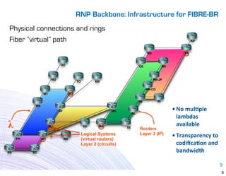
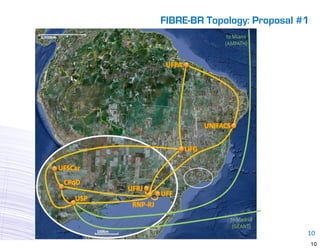
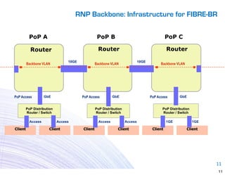
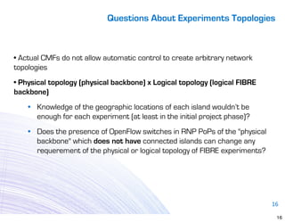
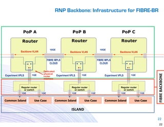
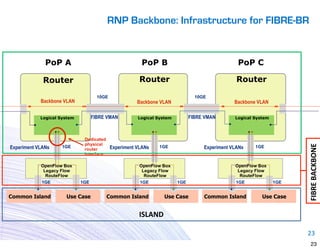
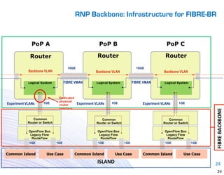

The document discusses the infrastructure for the FIBRE-BR testbed facility using RNP's backbone network. It proposes using a "virtual backbone" with logical topologies over the physical topology to provide dedicated resources for experiments. This would allow multiple experiments to run simultaneously without interference. Each experiment could select its own resources like servers and interfaces. Physical limitations require using the same equipment but virtualizing resources.


