Poka yoke implimentation on punching machine a case study

Abstract The paper represents a case study which focuses on Poka Yoke which is a concept coined by Japanese people. We have studied a system that eliminated the rework and increased productivity of the plant which results in achievement of 0 PPM as well; in the company based in Satpur, Nashik. There was a punching machine there in the plant which was punching a hole on a rear end cap of Mahindra Scorpio’s rear bumper. There were 4 metal clips which were fitted on that component before the part gets punched on punching machine. After some of the lots get punched, we observed that component is getting punched unless those clip fittings. At that time, company needs more time to fit metal clips on the component again which was time consuming. So this problem can be avoided by implementing Poka Yoke system to it. So, the aim of the project was avoid the mistake of missing of metal clip on it and make a system which will not allow to punch the hole unless and until all 4 metal clips are arranged on it. Keywords: Poka Yoke, Metal Clips
![IJRET: International Journal of Research in Engineering and Technology eISSN: 2319-1163 | pISSN: 2321-7308
_______________________________________________________________________________________
Volume: 04 Issue: 02 | Feb-2015, Available @ http://www.ijret.org 99
It makes use of some inductive proximity sensors to sense
the metal clips, whether they are there on its place or not.
All the sensors are used as a human eye which properly
checks the metal clip presence on the component.
By using some basic logics, that pneumatic punching
machine circuit was so arranged that; firstly, sensors will
sense the presence of the metal clips and then further
operation of the punching is done when we got the signal
from the electronic control panel which takes sensor output
as its input.
1.1 What is Poka Yoke?
Poka Yoke is a Japanese concept which means to avoid
(Yokeru) and mistakes (Poka). Main aim of Poka Yoke
concept is to make whole system error proof that means no
one can make mistake although some one wants to make
mistakes intentionally. It eliminates the defects or faults.
This term was coined by Shigeo Shingo in 1960s for the part
of Toyota Production System. The aim of poka-yoke is to
design the process so that mistakes can be detected and
corrected immediately, eliminating defects at the source. A
methodic approach to build up Poka-Yoke countermeasures
has been proposed by the APS methodology [1], which
consists in a three steps analysis of the risks to be managed:
1. Identification of the need
2. Identification of possible mistakes
3. Management of mistakes before satisfying the
need[1]
These steps are taken into consideration while thinking
about implementation of Poka Yoke system in any field
because this methodology remains same at all the situations
and conditions.
Fig -2: Poka Yoke Principle
Above figure shows the concept of the Poka Yoke system.
In upper diagram, size of both holes are same, therefore
there may be mistake of putting positive terminal into
negative hole but on the other hand, in lower figure, the
sizes of both the holes are different which results in
avoiding the misplacement of the terminal into wrong hole.
2. PROBLEM STATEMENT
The problem in this case was missing metal clips. That
component which was to be punch sometimes sent further
for punching operation without conforming all metal pins
are there on its place or not. These were results in wastage
of times which indirectly affect productivity of the plant.
This was the problem.
From below chart, we can conclude that in each lot of 50
components, we found 2 to 3 component such that metal
clips were missed so if we calculate total PPM of the
readings we got; that was too high which leads to wastage of
so much time.
0
0.5
1
1.5
2
2.5
3
3.5
4
4.5
1st 2nd 3rd 4th 5th 6th
Defects/50 components
Chart -1: Number of Defects/50 components (6 lots)](data:image/gif;base64,R0lGODlhAQABAIAAAAAAAP///yH5BAEAAAAALAAAAAABAAEAAAIBRAA7)
Recommended
Recommended
More Related Content
Viewers also liked
Similar to Poka yoke implimentation on punching machine a case study
Similar to Poka yoke implimentation on punching machine a case study (20)
More from eSAT Journals
More from eSAT Journals (20)
Recently uploaded
Recently uploaded (20)
Poka yoke implimentation on punching machine a case study
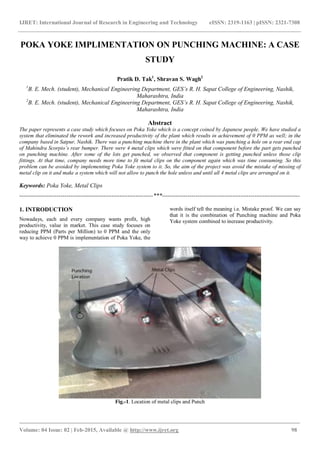
- 1. IJRET: International Journal of Research in Engineering and Technology eISSN: 2319-1163 | pISSN: 2321-7308 _______________________________________________________________________________________ Volume: 04 Issue: 02 | Feb-2015, Available @ http://www.ijret.org 98 POKA YOKE IMPLIMENTATION ON PUNCHING MACHINE: A CASE STUDY Pratik D. Tak1 , Shravan S. Wagh2 1 B. E. Mech. (student), Mechanical Engineering Department, GES’s R. H. Sapat College of Engineering, Nashik, Maharashtra, India 2 B. E. Mech. (student), Mechanical Engineering Department, GES’s R. H. Sapat College of Engineering, Nashik, Maharashtra, India Abstract The paper represents a case study which focuses on Poka Yoke which is a concept coined by Japanese people. We have studied a system that eliminated the rework and increased productivity of the plant which results in achievement of 0 PPM as well; in the company based in Satpur, Nashik. There was a punching machine there in the plant which was punching a hole on a rear end cap of Mahindra Scorpio’s rear bumper. There were 4 metal clips which were fitted on that component before the part gets punched on punching machine. After some of the lots get punched, we observed that component is getting punched unless those clip fittings. At that time, company needs more time to fit metal clips on the component again which was time consuming. So this problem can be avoided by implementing Poka Yoke system to it. So, the aim of the project was avoid the mistake of missing of metal clip on it and make a system which will not allow to punch the hole unless and until all 4 metal clips are arranged on it. Keywords: Poka Yoke, Metal Clips --------------------------------------------------------------------***---------------------------------------------------------------------- 1. INTRODUCTION Nowadays, each and every company wants profit, high productivity, value in market. This case study focuses on reducing PPM (Parts per Million) to 0 PPM and the only way to achieve 0 PPM is implementation of Poka Yoke, the words itself tell the meaning i.e. Mistake proof. We can say that it is the combination of Punching machine and Poka Yoke system combined to increase productivity. Fig.-1. Location of metal clips and Punch
- 2. IJRET: International Journal of Research in Engineering and Technology eISSN: 2319-1163 | pISSN: 2321-7308 _______________________________________________________________________________________ Volume: 04 Issue: 02 | Feb-2015, Available @ http://www.ijret.org 99 It makes use of some inductive proximity sensors to sense the metal clips, whether they are there on its place or not. All the sensors are used as a human eye which properly checks the metal clip presence on the component. By using some basic logics, that pneumatic punching machine circuit was so arranged that; firstly, sensors will sense the presence of the metal clips and then further operation of the punching is done when we got the signal from the electronic control panel which takes sensor output as its input. 1.1 What is Poka Yoke? Poka Yoke is a Japanese concept which means to avoid (Yokeru) and mistakes (Poka). Main aim of Poka Yoke concept is to make whole system error proof that means no one can make mistake although some one wants to make mistakes intentionally. It eliminates the defects or faults. This term was coined by Shigeo Shingo in 1960s for the part of Toyota Production System. The aim of poka-yoke is to design the process so that mistakes can be detected and corrected immediately, eliminating defects at the source. A methodic approach to build up Poka-Yoke countermeasures has been proposed by the APS methodology [1], which consists in a three steps analysis of the risks to be managed: 1. Identification of the need 2. Identification of possible mistakes 3. Management of mistakes before satisfying the need[1] These steps are taken into consideration while thinking about implementation of Poka Yoke system in any field because this methodology remains same at all the situations and conditions. Fig -2: Poka Yoke Principle Above figure shows the concept of the Poka Yoke system. In upper diagram, size of both holes are same, therefore there may be mistake of putting positive terminal into negative hole but on the other hand, in lower figure, the sizes of both the holes are different which results in avoiding the misplacement of the terminal into wrong hole. 2. PROBLEM STATEMENT The problem in this case was missing metal clips. That component which was to be punch sometimes sent further for punching operation without conforming all metal pins are there on its place or not. These were results in wastage of times which indirectly affect productivity of the plant. This was the problem. From below chart, we can conclude that in each lot of 50 components, we found 2 to 3 component such that metal clips were missed so if we calculate total PPM of the readings we got; that was too high which leads to wastage of so much time. 0 0.5 1 1.5 2 2.5 3 3.5 4 4.5 1st 2nd 3rd 4th 5th 6th Defects/50 components Chart -1: Number of Defects/50 components (6 lots)
- 3. IJRET: International Journal of Research in Engineering and Technology eISSN: 2319-1163 | pISSN: 2321-7308 _______________________________________________________________________________________ Volume: 04 Issue: 02 | Feb-2015, Available @ http://www.ijret.org 100 3. PROBLEM SOLUTION Fig -3: System Design (Problem solution) There is a very smart solution to this problem which is expressed in about circuit diagram. The main task we have to do is to stop the air flow from the compressor to pneumatic cylinder if any one of the metal clip is missing. Required components 4 Proximity Sensor Solenoid Valve DCV (Pedal operated) Double acting Cylinder Electronic Control Panel (PLC) Power Supply and Compressor Firstly, simple pneumatic circuit is made which can operate the cylinder according to its stroke. To integrate Poka Yoke system to this pneumatic system is by adding a solenoid valve between compressor and direction control valve. The solenoid valve gets opened when it will get signal from electronic control panel (PLC). Programmable Logic Controller will take input from Inductive proximity sensor and will process the signal accordingly and sent to solenoid valve and solenoid valve will send air to pass through cylinder. Inductive proximity Sensor Metal Clip Fig-4: Inductive Proximity Sensor working principle Its main function is to collect the information on system status and to feed it to the micro-processor(s) for controlling the whole system. Eddy current proximity sensors are used to detect non-magnetic but conductive material. They are comprised of a coil, an oscillator, a detector and a triggering circuit. Figure-4 shows the construction of eddy current proximity switch. When an alternating current is passed through this coil, an alternative magnetic field is generated. [3]. If a metal object comes in that proximity of the coil, then eddy currents are induced in the object due to the magnetic field. These eddy currents create their own magnetic field which distorts the magnetic field responsible for their generation. As a result, impedance of the coil changes and so the amplitude of alternating current varies. This can be used to trigger a switch at some pre-determined level of change in current.[3]. In this system, PLC, solenoid valve and Proximity sensor plays main role to implement Poka Yoke.
- 4. IJRET: International Journal of Research in Engineering and Technology eISSN: 2319-1163 | pISSN: 2321-7308 _______________________________________________________________________________________ Volume: 04 Issue: 02 | Feb-2015, Available @ http://www.ijret.org 101 Fig.-5. Fitting of Proximity Sensor according to metal clip Position Programmable Logic Controller Fig-6: Programmable Logic Control Block Diagram[4] PLC has 2 main compartments in it. These are Input interface, Data Processing unit (microprocessor) and Output interface as shown in above block diagram. 4 proximity sensors are connected to the input interface of PLC. It sends the data to the microprocessor. Power supply is given to microprocessor and memory is inside the processing unit to store the data it has got. Microprocessor is pre-programmed according to our need. In this case it is programmed that unless and until the entire metal clip set is not sensed; PLC will not send positive output i.e. it will not open the solenoid valve. PLCs are generally used for incorporating automation in open loop systems where processes are to be performed in a sequential manner. PLCs are used for automation of assembly lines in industries. They are generally designed for multiple input multiple output (MIMO) systems.[4]
- 5. IJRET: International Journal of Research in Engineering and Technology eISSN: 2319-1163 | pISSN: 2321-7308 _______________________________________________________________________________________ Volume: 04 Issue: 02 | Feb-2015, Available @ http://www.ijret.org 102 Fig.-7. PLC Position of Sensors: Fig-8: Modeling of Sensor positions Above modeling shows approximate position of four sensors for which detail dimensions are shown in below diagram. All the sensors should fit on its position so that all the sensors can sense the presence of the metal clips on its place.
- 6. IJRET: International Journal of Research in Engineering and Technology eISSN: 2319-1163 | pISSN: 2321-7308 _______________________________________________________________________________________ Volume: 04 Issue: 02 | Feb-2015, Available @ http://www.ijret.org 103 Fig-9: Dimensions according to metal clip position Fig-10: Actual Mountings of sensors
- 7. IJRET: International Journal of Research in Engineering and Technology eISSN: 2319-1163 | pISSN: 2321-7308 _______________________________________________________________________________________ Volume: 04 Issue: 02 | Feb-2015, Available @ http://www.ijret.org 104 Some of the other standard components in the system: Fig-11: Solenoid Valve Fig.12. 5/2 Direction Control Valve (Pedal operated)
- 8. IJRET: International Journal of Research in Engineering and Technology eISSN: 2319-1163 | pISSN: 2321-7308 _______________________________________________________________________________________ Volume: 04 Issue: 02 | Feb-2015, Available @ http://www.ijret.org 105 Fig.-13. Double acting cylinder Fig-14: Final Model 4. RESULT Table-1 Result Data Lots No. of Sample Missed pins component PPM (Before) PPM (After) (Result) 1 50 2 40000 0 2 50 1 20000 0 3 50 0 0 0 4 50 1 20000 0 5 50 4 80000 0 6 50 3 60000 0 Average 300 11 36666.66 0
- 9. IJRET: International Journal of Research in Engineering and Technology eISSN: 2319-1163 | pISSN: 2321-7308 _______________________________________________________________________________________ Volume: 04 Issue: 02 | Feb-2015, Available @ http://www.ijret.org 106 0 0.5 1 1.5 2 2.5 3 3.5 4 4.5 1st 2nd 3rd 4th 5th 6th Before After Chart-2: Result before and after From above table and chart we can see the result we obtained after implementation of the Poka Yoke concept to the punching machine. 5. CONCLUSION From this project we have got positive output which meets organizational requirement i.e. Increased productivity Achieved 0 PPM Eliminated rework time No chance for mistake A very simple technique is used to implement Poka Yoke to the punching machine which was so profitable. Poka Yoke eliminated mistakes and rework time. ACKNOWLEDGEMENTS We take this opportunity to express our deepest sense of gratitude and sincere thanks to those who have helped us in completing this task. We express our sincere thanks to our thanks to our guide Prof. S. V. Dawange Sir, Lecturer in Mechanical Engineering Department, who has given us valuable suggestions. We are very thankful to Prof. K. V. Chandratre Sir, Head of the Mechanical Engineering Department for cooperation and encouragement for collecting the information and preparation of data. We, also, thank to Mr. Mangesh Bachhav sir for helping us. REFERENCES [1]. Ivan Fantin (2014). Applied Problem Solving. Method, Application, root causes, countermeasures, Poka-Yoke and A3. How to make things happen to solve problems. Milan, Italy; Createspace, an Amazon company. ISBN 978- 1499122282 [2]. Dr. Shrikrishna N. Joshi, Mechantronics and Manufacturing Automation (Web), http://nptel.ac.in/courses/112103174/5 [3]. Dr. Shrikrishna N. Joshi, Mechantronics and Manufacturing Automation (Web), http://nptel.ac.in/courses/112103174/13 BIOGRAPHIES Pratik D. Tak, Pursuing Final Year in Bachelor of Mechanical Engineering degree from GES’s R.H.S.C.O.E, Nasik, under the affiliation of University of Pune, Maharashtra, India. Shravan S. Wagh, Pursuing Final Year in Bachelor of Mechanical Engineering degree from GES’s R.H.S.C.O.E, Nasik, under the affiliation of University of Pune, Maharashtra, India.