Optimizing the manufacturing of the nose cone of a race car

can be employed right from the mold making process to the actual manufacturing of a composite part. It focuses on developing a cost-effective, time-saving and reusable mold that can withstand relatively high pressures and temperatures and serve as an alternative to the current industry norms. The challenge lies in effectively eliminating the pattern making stage without compromising on the surface finish of the mold. Considering the high velocities that race cars travel with, nose cone geometry plays a critical role in dictating the aerodynamic design that provides minimum drag and ensures optimum performance of the car. The first step in achieving this goliath of a step has its foundation in making a coherent assembly of the nose cone while maintaining its structural integrity and strength. Based on the experimental data, the lamination strategy was worked out to adjudicate the carbon fiber prepreg layers on the nose cone mold. Key Words: Composites, Mold, Carbon fiber, Prepregs, Nose Cone, Joggle technique

Recommended
Recommended
More Related Content
What's hot
What's hot (18)
Similar to Optimizing the manufacturing of the nose cone of a race car
Similar to Optimizing the manufacturing of the nose cone of a race car (20)
More from eSAT Journals
More from eSAT Journals (20)
Recently uploaded
Recently uploaded (20)
Optimizing the manufacturing of the nose cone of a race car
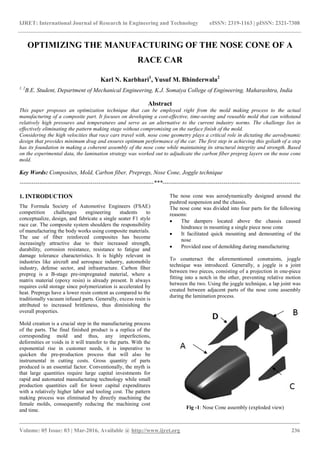
- 1. IJRET: International Journal of Research in Engineering and Technology eISSN: 2319-1163 | pISSN: 2321-7308 _______________________________________________________________________________________ Volume: 05 Issue: 03 | Mar-2016, Available @ http://www.ijret.org 236 OPTIMIZING THE MANUFACTURING OF THE NOSE CONE OF A RACE CAR Karl N. Karbhari1 , Yusuf M. Bhinderwala2 1, 2 B.E. Student, Department of Mechanical Engineering, K.J. Somaiya College of Engineering, Maharashtra, India Abstract This paper proposes an optimization technique that can be employed right from the mold making process to the actual manufacturing of a composite part. It focuses on developing a cost-effective, time-saving and reusable mold that can withstand relatively high pressures and temperatures and serve as an alternative to the current industry norms. The challenge lies in effectively eliminating the pattern making stage without compromising on the surface finish of the mold. Considering the high velocities that race cars travel with, nose cone geometry plays a critical role in dictating the aerodynamic design that provides minimum drag and ensures optimum performance of the car. The first step in achieving this goliath of a step has its foundation in making a coherent assembly of the nose cone while maintaining its structural integrity and strength. Based on the experimental data, the lamination strategy was worked out to adjudicate the carbon fiber prepreg layers on the nose cone mold. Key Words: Composites, Mold, Carbon fiber, Prepregs, Nose Cone, Joggle technique --------------------------------------------------------------------***---------------------------------------------------------------------- 1. INTRODUCTION The Formula Society of Automotive Engineers (FSAE) competition challenges engineering students to conceptualize, design, and fabricate a single seater F1 style race car. The composite system shoulders the responsibility of manufacturing the body works using composite materials. The use of fiber reinforced composites has become increasingly attractive due to their increased strength, durability, corrosion resistance, resistance to fatigue and damage tolerance characteristics. It is highly relevant in industries like aircraft and aerospace industry, automobile industry, defense sector, and infrastructure. Carbon fiber prepreg is a B-stage pre-impregnated material, where a matrix material (epoxy resin) is already present. It always requires cold storage since polymerization is accelerated by heat. Prepregs have a lower resin content as compared to the traditionally vacuum infused parts. Generally, excess resin is attributed to increased brittleness, thus diminishing the overall properties. Mold creation is a crucial step in the manufacturing process of the parts. The final finished product is a replica of the corresponding mold and thus, any imperfections, deformities or voids in it will transfer to the parts. With the exponential rise in customer needs, it is imperative to quicken the pre-production process that will also be instrumental in cutting costs. Gross quantity of parts produced is an essential factor. Conventionally, the myth is that large quantities require large capital investments for rapid and automated manufacturing technology while small production quantities call for lower capital expenditures with a relatively higher labor and tooling cost. The pattern making process was eliminated by directly machining the female molds, consequently reducing the machining cost and time. The nose cone was aerodynamically designed around the pushrod suspension and the chassis. The nose cone was divided into four parts for the following reasons: The dampers located above the chassis caused hindrance in mounting a single piece nose cone It facilitated quick mounting and demounting of the nose Provided ease of demolding during manufacturing To counteract the aforementioned constraints, joggle technique was introduced. Generally, a joggle is a joint between two pieces, consisting of a projection in one-piece fitting into a notch in the other, preventing relative motion between the two. Using the joggle technique, a lap joint was created between adjacent parts of the nose cone assembly during the lamination process. Fig -1: Nose Cone assembly (exploded view)
- 2. IJRET: International Journal of Research in Engineering and Technology eISSN: 2319-1163 | pISSN: 2321-7308 _______________________________________________________________________________________ Volume: 05 Issue: 03 | Mar-2016, Available @ http://www.ijret.org 237 2. MOLD MANUFACTURING 2.1 Design The nose cone was designed using SolidWorks. It was then scaled up by 2% to account for any shrinkage and cut extruded from a cuboid to create the required mold. For machining the nose cone mold on a CNC machine, it was divided into two parts along its length and subsequently aligned using dowel pins. Fig -2: Draft analysis of Nose Cone mold Initially, the pull direction for releasing the part was specified towards the left of the page. It can be seen that areas of the mold either require a draft or have a negative draft (Fig -2). To counteract this, the nose cone was manufactured in 4 parts using a single mold. Part C and part D were released first in the direction perpendicular to the page. Further, part B followed by part A were released in the direction towards the left of the page (Fig -3). This resolved the draft angle issue. Fig -3: Part demolding 2.2 Material Selection Material selection for mold is an extremely important step as it directly determines the finish of the part along with considerable cost savings. Most commonly used products are made from either timber based products or aluminium. Other available options include copper, steel, brass, etc. that can be used either in a combination or by themselves. The selection of the mold material primarily depends upon the operating pressure, temperature, and dimensional accuracy. Medium Density Fiber Board (MDF) is the most conventional material having a high machinability value and ease of use when it comes to cutting complex shapes. It also maintains stability at moderately high temperatures. Composite blocks can be made by gluing several blocks or sheets together. Once the molds are machined, it can be worked upon with fine grade dry and wet sandpapers followed by buffing to achieve the desired finish and smoothness. Aluminium molds are extensively used in the industry. CAD files are made which are directly uploaded to the 5 axes milling machine that does the work with great accuracy and detail. This reduces the production time and gives increased quality in the final finish of the work. When it comes to aluminium, the expense isn’t the material but the tooling time. So although aluminium molds displayed better quality of work and are ideal for multiple uses of the same mold, in the end, it burns down to the cost of the material and machining, and thus MDF was preferred. There were three choices for the material: 1. Interior grade Medium Density Fiberboard 2. Exterior grade Medium Density Fiberboard 3. High-Density Fiberboard To decide the material for the manufacturing of the molds, the materials were heated in a muffle furnace at temperatures of 80°C, 120°C and 140°C. Properties Plain Interior grade MDF Plain Exterior grade MDF High- Density Fiberboard Standard density (kg/m3 ) 650-700 720-800 880-1020 Cost per sqm $14.66 $18.14 $24.21 Ability to be machined Consistent structure, density and a very smooth surface Better finish, making it suitable for laser cutting and milling operations More wood fiber per cubic meter than MDF board Expansion in water after 24 hours 7-9% 6-7% 5% Heat Test Observation Started fuming and chipping at temperature above 80°C Could successfully withstand temperature up to 140°C Could successfully withstand temperature up to 180°C Considering the overall properties and cost, 8 feet x 4 feet x 25mm sheets of exterior grade MDF were selected.
- 3. IJRET: International Journal of Research in Engineering and Technology eISSN: 2319-1163 | pISSN: 2321-7308 _______________________________________________________________________________________ Volume: 05 Issue: 03 | Mar-2016, Available @ http://www.ijret.org 238 2.3 Mold Coatings The molds had to retain their shape and surface finish at 120°C and 4 bar pressure. Following are the layers which were applied via spraying to achieve a good finish: 1. Sealer coat: As the Exterior Grade MDF was porous, a sealer coat had to be applied to make it non-porous and provide a good bonding surface for other coats. Fig -4: Sealer coat 2. Primer coat: Primer coat acted as a base layer which could be easily sanded and smoothened to provide an almost flat layer for the top coat. The primer also provided a good adhesive bonding with the high gloss coats. MechsterTM 9000G-PM was selected, which is a specially formulated gel-coat based on Orthophthalate Polyester Resin. MechsterTM 9000G-PM is designed to have: [1]. Excellent surface finish [2]. Faster curing time (6 minutes at 30°C) [3]. Easier Vertical surface applications [4]. Minimal Sagging [5]. Easy sanding / polishing to smoothness Fig -5: Primer coat 3. High gloss coat: Mechster 8100 (FC), a specially formulated finishing coating for patterns was selected. It offered excellent coverage and a uniform coating which is hard and thermally stable, thus, making it suitable for use in the autoclave. After complete cure it was suitably polished, rubbed and buffed to achieve the desired gloss and surface finish. Fig -6: High gloss coat 3. PART MANUFACTURING 3.1 Strength Calculations The next step was to decide the number of layers for the lamination process. Various combinations of samples with 200GSM, 380GSM, and 630GSM Carbon Fiber plies with core materials like Lantor Soric XF and Rohacell were created. Using the ASTM D790 Flexural Bending Test, the maximum load the specimen could endure was calculated. Considering the specimen to be a simply supported beam. σ = 3PL/(2bd2 ) Where, σ = stress in the outer fibers at the midpoint, (MPa) P = load at a given point in the load-deflection curve, (N) b = width of beam tested, (mm) d = depth of beam tested, (mm) L = span length of beam tested, (mm) For the given test sample of a size of 200 x 10mm, the flexural stress turns out to be 62.64 MPa. Using this result, calculating the maximum load: Here, σ = 62.64 MPa b = 10 mm L = 112 mm d = 7.01 mm P = (2*62.64*10*(7.01) 2 / (3*785.2)) ∴ P=183.222 N 3.2 Carbon Fiber Prepreg Layup The joggle technique was employed for mating of the four different parts as well as to provide the structural rigidity of the assembly. The Polytetrafluoroethylene (PTFE) tape prevented the curing of two consecutive prepreg laminates when placed between them, enabling the manufacturing of the four parts from a single mold in one cycle. The goal was to achieve the same thickness throughout the nose cone assembly while implementing the joggle technique. The laminates in the joggle were so arranged that the thickness on the left-hand side of the PTFE tape and the right-hand
- 4. IJRET: International Journal of Research in Engineering and Technology eISSN: 2319-1163 | pISSN: 2321-7308 _______________________________________________________________________________________ Volume: 05 Issue: 03 | Mar-2016, Available @ http://www.ijret.org 239 side were almost equal (Fig 8). It ensured that when two parts mated, the total thickness at the joggle was the same as the total thickness of the nose cone. This warranted a flush assembly of the parts which was not only aesthetically pleasing but also constrained movement of adjacent parts. The front of the nose cone and its perimeter was reinforced with a total of 1610 GSM carbon fiber (Fig 7). This provided the impact resistance on the front and maintained overall structural integrity of the assembly. Fig -7: Joggle technique used in Nose Cone Referring to Fig -7, PREPREG 200 GSM THICKNESS = 0.22 mm PREPREG 380 GSM THICKNESS = 0.42 mm PREPREG 630 GSM THICKNESS = 0.66 mm TOTAL THICKNESS ON LHS = 0.22+0.42+0.22 = 0.86 mm TOTAL THICKNESS ON RHS = 0.66+0.22 = 0.88 mm Fig -8: Nose Cone layup guide Fig -7: Nose Cone CONCLUSION This paper successfully integrates designing, material selection, manufacturing process, and quality assurance. The paper contributes to advancements in cost effective manufacturing of composite parts. Methodology of making molds is discussed wherein the molds have negligible volume shrinkage, resist heat distortion, and are stress free. Results are presented that show the approach of the joggle technique during the lamination process of the part; in addition, the use and application of various gel coatings applied on the mold has been enumerated. The proposed method provides an intermediate path that ensures cost reduction along with striking a balance on providing a good surface finish to the mold. REFERENCES [1]. Nadir Ayrilmis. “Effect of panel density on dimensional stability of medium and high density fiberboards.” J Mater Sci (2007) 42:8551–8557 DOI 10.1007/s10853-007-1782-8 [2]. “Standard Test Methods for Flexural Properties of Unreinforced and Reinforced Plastics and Electrical Insulating Materials.” Designation: D 790 – 02 [3]. James Meredith, Edward Bilson, Richard Powe, Ed Collings, Kerry Kirwan. “A performance versus cost analysis of prepreg carbon fibre epoxy energy absorption structures.” www.elsevier.com/locate/compstruct [4]. Agarwal BD, Broutman LJ, Chandrashekhara K. “Analysis and performance of fiber composites.” 3rd ed. Wiley; 2006. BIOGRAPHIES Karl N. Karbhari The author is an undergraduate student of mechanical engineering at K. J. Somaiya College of Engineering, Mumbai, India. Yusuf M. Bhinderwala The author is an undergraduate student of mechanical engineering at K. J. Somaiya College of Engineering, Mumbai, India.