SlideShare a Scribd company logo
1 of 17
Download to read offline
Measuring the elastic modulus and the residual 
   stress of free‐standing thin films using 
   stress of free‐standing thin films using
        nanoindentation techniques


     E. G. Herbert1, W. C. Oliver1, M. P. De Boer2, G. M. Pharr3,
                   B. Peters1, and A. Lumsdaine1
     1Agilent Technologies, Inc., Nanomechanical Instruments Operations
     2Carnegie Mellon, Dept. of Mechanical Engineering and Sandia Natl. Lab
     3U i
      University of TN, Dept. of Materials Science and Engineering and ORNL
              it f TN D t f M t i l S i              dE i      i     d ORNL
MOTIVATION AND GOALS

MEMS:  mechanical characterization forms the basis to quickly and reliably 
simulate complex devices and thus avoids the need to incorporate 
simulate complex devices and thus avoids the need to incorporate
extensive prototyping.

Fundamental materials science: controlling the sample geometry and 
Fundamental materials science: controlling the sample geometry and
dimensions allows enhances our capability to systematically explore 
structure‐property relationships linked to microstructure, film thickness, 
fabrication, and deposition techniques.
fabrication and deposition techniques

Among the challenges:  generating reliable data (well understood, robust 
experiments that are an accurate reflection of the applied model) and 
     i   t th t               t    fl ti     f th     li d   d l) d
experimental verification. 
MOTIVATION AND GOALS
What we’re after:
 • The elastic modulus and the residual stress in free‐standing, metallic thin 
   films
What we set out to accomplish:
1. Simple mathematical model that is easy to implement experimentally
     • Uniaxial tension stretching not bending
                tension, stretching not bending
2. Controlling the sample geometry, consistent with assumptions of the model
    • Dimensional analysis identifies limitations of the model
3. Robust experiment
    • Stiffness‐displacement, NOT load‐displacement – minimize measurement 
      errors associated with thermal drift
      errors associated with thermal drift
4. Experimental verification
    • Material selection: Aluminum 5wt% copper
PROPOSED MODEL
                   l
                                                                                    z
                                 P
                                                                   F1                                      F2


                             P
                                                                         θ                       θ
     h    w                                                                                            y

                                                         support
                                                           post
support
                                     thin film bridge
  post                                                                                  P

              wedge indenter tip


                                                                        Δl                  2h
                                                                   ε=      =                          −1
                         +
                                                                                     ⎡      ⎛ 2h ⎞⎤
   F                                        P
                        ↑ ∑ Fz = 0 ⇒ F =
                                                                        l
σ = = Eε + σ r                                                                 l sin ⎢tan −1⎜ ⎟⎥
                                         2 sinθ
   A                                                                                        ⎝ l ⎠⎦
                                                                                     ⎣


   8 AEh 3 8 Aσ r h 3 4 Aσ r h                             dP 24 AEh 2 24 Aσ r h 2 4 Aσ r
P=        −          +                                  S=    =       −           +
        3       3                                                  3         3
                         l                                 dh                         l
      l       l                                                  l         l
THE EFFECT OF THERMAL DRIFT
                                                                                  80
                      100

          mple (μN)             Δh = dh/dt (time)
                      80
                                                                                  60
                                ΔP = dh/dt (time)(Ksprings)


                                                                                        Stiffne (N/m
                      60
                                                                                  40
Load On Sam


                                                                                              ess
                      40
                                                                                  20
                      20


                                                                                                   m)
                                                                                  0
                                                          length = 150 µm
                       0                                  width = 22 µm
                                                          thickness = 0.547 µm

                                                                                  -20
                      -20
                            0              1000               2000         3000
                                      Displacement (nm)
PROPOSED TECHNIQUE

ADVANTAGES:                          MODEL ASSUMPTIONS:
• minimizes the effect of thermal
  minimizes the effect of thermal    • center loading
                                       center loading
  drift                              • normal, elastic deformation
                                     • bending moments may be ignored
• improved signal to noise ratio
                                     • rigid support posts
• model is simple to implement 
                                     • the film is flat
  mathematically


                     DIMENSIONAL ANALYSIS:
                                            π 2 ⎛σr ⎞
                 π 4 ⎛t ⎞ π 2 σr
      3π 4                                               π 4 ⎛t ⎞
                2        2                                          2
             ⎛h⎞
 Sl                                            ⎜    ⎟ >>
    =        ⎜⎟+     ⎜⎟+                                     ⎜⎟
                                             2 ⎝E⎠
             ⎝l⎠  6 ⎝l ⎠                                   6 ⎝l ⎠
 AE    8                   2E
EXPERIMENTAL VERIFICATION
•   Al 5wt% Cu
                                                      • dc‐magnetron sputtered at 175 oC
•   length = 150, 300, and 500 µm
                                                      • posts are poly Si
•   width = 22 µm
                                                      • 50 nm TiN protective coating
                                                                   p                g
•   thickness  0.547 µm
    thickness = 0.547 µm
                                                      • wet etchant release with HF
•   nominal E = 70 GPa
                                                      • selective wet etch of TiN coating
•   est. via electrostatic, E = 74.4 GPa ± 2.8,    
σ r = 29.9 MPa ± 0.3
 = 
STIFFNESS‐DISPLACEMENT RESPONSE
                  40
                                                                 frequency = 20 Hz
                  35               Loading                       osc. amp. = 30 nm
                                   Unloading
                                                                 length = 150 µm
                  30
 tiffness (N/m)


                                                                 width = 22 µm
                  25                                             thickness = 0.571 µm
                                                                 strain = 0.04%
                  20
                  15
                                                               estimated by electrostatic
                                                               estimated by electrostatic
St


                  10
                                                               techniques:
                                                               E = 74.4 GPa ± 3.8%
                  5
                                                               σ r = 29.9 MPa ± 1%
                  0
                       -400    0      400 800 1200 1600 2000
                                   Displacement (nm)
STIFFNESS‐DISPLACEMENT RESPONSE
                  40
                                                                      frequency = 20 Hz
                  35                Loading                           osc. amp. = 30 nm
                                    Unloading
                                                                      length = 150 µm
                  30
 tiffness (N/m)


                                                                      width = 22 µm
                  25                                                  thickness = 0.571 µm
                              Misalignment,                           strain = 0.04%
                  20
                                  1.6o
                  15
                                                                    estimated by electrostatic
                                                                    estimated by electrostatic
St


                  10
                                                                    techniques:
                                              peak‐to‐peak =        E = 74.4 GPa ± 3.8%
                  5
                                                                    σ r = 29.9 MPa ± 1%
                                              2 2 ( rms ) = 85 nm
                  0
                       -400     0      400 800 1200 1600 2000
                                    Displacement (nm)
STIFFNESS‐DISPLACEMENT RESPONSE
                  40
                                                                                frequency = 20 Hz
                           E = 75.3 GPa +/- 1%
                  35                                                            osc. amp. = 30 nm
                           σr = 28.7 MPa +/ 0 6%
                                28 7     +/- 0.6%
                                                                                length = 150 µm
 tiffness (N/m)


                  30                                                            width = 22 µm
                                                                                thickness = 0.571 µm
                  25
                                                                                strain = 0.04%
                  20
                                                                  2
                                          y = 9.628 + 6.662E+12x R = 0.9992
                                                                              estimated by electrostatic
                                                                              estimated by electrostatic
                  15
St


                                                                  2
                                                                              techniques:
                                          y = 9.631 + 6.685E+12x R = 0.9992

                                                                              E = 74.4 GPa ± 3.8%
                                                                 2
                                          y = 9.651 + 6.74E+12x R = 0.9995
                  10
                                                                              σ r = 29.9 MPa ± 1%
                                                                  2
                                          y = 9.514 + 6.809E+12x R = 0.9994

                  5
                           1x10-12 2x10-12 3x10-12 4x10-12 5x10-12
                       0
                               Displacement2 (m2)
                                  p          (
STIFFNESS‐DISPLACEMENT RESPONSE
                  80
                            length = 150 μm
                  70        disp. = 3 μm, 3x
                            osc. amp. = 40 nm
                  60
Stiffness (N/m)


                                        length = 300 μm              frequency = 45 Hz
                  50
                                        disp. = 6 μm, 2x
                                                                     width = 22 µm
                                                                     width = 22 µm
        s


                                        osc. amp. = 60 nm
                  40
                                                                     thickness = 0.547 µm
                  30                                                 strain = 0.08%
                                                length = 500 μm
                                                disp. = 10 μm, 3
S


                                                di             3x
                  20
                                                osc. amp. = 120 nm
                  10

                  0
                           1.5x10⁻¹¹ 3x10-11 4.5x10⁻¹¹ 6x10-11
                       0
                             Displacement2 (m2)
EXPERIMENTAL VERIFICATION
                       GPa)


                              80
                                                                                40


                                                                                     Re
              sticity (G


                              70


                                                                                      esidual Stress (MPa)
                                                                                                             As expected, the modulus 
                                                                                                             is independent of length 
                              60
                                                                                30                           and bending behavior 
                              50
Modulus of Elas


                                                                                                             Residual stress, on the 
                                                                                                             other hand, is effected by:
                              40                                                20                           1.  CTE = 23x10‐6/K
                                           E, proposed technique
                                                                                                                 ΔT = 3 oC
                              30           E, electrostatic technique
                                                                                                                  σ = 5.2 MPa
                                           σr , proposed technique
                              20                                                                             2.  Bending behavior
                                                                                10
                                           σr , electrostatic technique
                              10
                                                                                0
                              0
                              100   200       300          400            500
                                    Bridge Length (μm)
                                        g     g (μ )
CLOSING REMARKS
• We have proposed a simple model to measure the elastic modulus and residual 
  stress of free‐standing metallic thin films
  ~ Based on the relationship between stiffness and displacement because it
    Based on the relationship between stiffness and displacement because it 
    minimizes the effects of thermal drift
  ~ Model assumes normal, elastic deformation of a flat film that does not support 
    bending moments and is rigidly mounted – the model is simple to implement 
    bd                  d      dl        dh           dl        l        l
    mathematically and dimensional analysis identifies the appropriate limits
• Experimental verification of the proposed technique was provided by measuring 
  the elastic modulus and residual stress of four Al/5wt% Cu free‐standing films
  ~ E matches within 2% of the result obtained by electrostatic actuation, 
    independent of the observed bending
    independent of the observed bending
  ~ σ r matches within 19.1% of the result obtained by electrostatic actuation, 
    discrepancy attributed to the CTE (ΔT = 3oC) and/or bending behavior –
    dimensional analysis predicted the overestimation

More Related Content

Similar to Elastic Modulus And Residual Stress Of Thin Films

Basic Nanoindentation Of Viscoelastic Solids
Basic Nanoindentation Of Viscoelastic SolidsBasic Nanoindentation Of Viscoelastic Solids
Basic Nanoindentation Of Viscoelastic Solidserikgherbert
 
국내외웹최신동향및발전방향 Sk컴즈 황현수
국내외웹최신동향및발전방향 Sk컴즈 황현수국내외웹최신동향및발전방향 Sk컴즈 황현수
국내외웹최신동향및발전방향 Sk컴즈 황현수경임 김
 
Fatigue behavior of welded steel
Fatigue behavior of welded steelFatigue behavior of welded steel
Fatigue behavior of welded steelAygMA
 
080926_Creative Environment
080926_Creative Environment080926_Creative Environment
080926_Creative Environmentmiyamura
 
CRF-Filters: Discriminative Particle Filters for Sequential State Estimation
CRF-Filters: Discriminative Particle Filters for Sequential State EstimationCRF-Filters: Discriminative Particle Filters for Sequential State Estimation
CRF-Filters: Discriminative Particle Filters for Sequential State Estimationcijat
 

Similar to Elastic Modulus And Residual Stress Of Thin Films (9)

Lesson8
Lesson8Lesson8
Lesson8
 
Basic Nanoindentation Of Viscoelastic Solids
Basic Nanoindentation Of Viscoelastic SolidsBasic Nanoindentation Of Viscoelastic Solids
Basic Nanoindentation Of Viscoelastic Solids
 
국내외웹최신동향및발전방향 Sk컴즈 황현수
국내외웹최신동향및발전방향 Sk컴즈 황현수국내외웹최신동향및발전방향 Sk컴즈 황현수
국내외웹최신동향및발전방향 Sk컴즈 황현수
 
Nano-IV(2005) Kanda et.al
Nano-IV(2005) Kanda et.alNano-IV(2005) Kanda et.al
Nano-IV(2005) Kanda et.al
 
Pll Basic
Pll BasicPll Basic
Pll Basic
 
Fatigue behavior of welded steel
Fatigue behavior of welded steelFatigue behavior of welded steel
Fatigue behavior of welded steel
 
Keys
Keys Keys
Keys
 
080926_Creative Environment
080926_Creative Environment080926_Creative Environment
080926_Creative Environment
 
CRF-Filters: Discriminative Particle Filters for Sequential State Estimation
CRF-Filters: Discriminative Particle Filters for Sequential State EstimationCRF-Filters: Discriminative Particle Filters for Sequential State Estimation
CRF-Filters: Discriminative Particle Filters for Sequential State Estimation
 

Recently uploaded

AI as an Interface for Commercial Buildings
AI as an Interface for Commercial BuildingsAI as an Interface for Commercial Buildings
AI as an Interface for Commercial BuildingsMemoori
 
Install Stable Diffusion in windows machine
Install Stable Diffusion in windows machineInstall Stable Diffusion in windows machine
Install Stable Diffusion in windows machinePadma Pradeep
 
Story boards and shot lists for my a level piece
Story boards and shot lists for my a level pieceStory boards and shot lists for my a level piece
Story boards and shot lists for my a level piececharlottematthew16
 
Streamlining Python Development: A Guide to a Modern Project Setup
Streamlining Python Development: A Guide to a Modern Project SetupStreamlining Python Development: A Guide to a Modern Project Setup
Streamlining Python Development: A Guide to a Modern Project SetupFlorian Wilhelm
 
Advanced Test Driven-Development @ php[tek] 2024
Advanced Test Driven-Development @ php[tek] 2024Advanced Test Driven-Development @ php[tek] 2024
Advanced Test Driven-Development @ php[tek] 2024Scott Keck-Warren
 
Gen AI in Business - Global Trends Report 2024.pdf
Gen AI in Business - Global Trends Report 2024.pdfGen AI in Business - Global Trends Report 2024.pdf
Gen AI in Business - Global Trends Report 2024.pdfAddepto
 
DevEX - reference for building teams, processes, and platforms
DevEX - reference for building teams, processes, and platformsDevEX - reference for building teams, processes, and platforms
DevEX - reference for building teams, processes, and platformsSergiu Bodiu
 
"Debugging python applications inside k8s environment", Andrii Soldatenko
"Debugging python applications inside k8s environment", Andrii Soldatenko"Debugging python applications inside k8s environment", Andrii Soldatenko
"Debugging python applications inside k8s environment", Andrii SoldatenkoFwdays
 
Developer Data Modeling Mistakes: From Postgres to NoSQL
Developer Data Modeling Mistakes: From Postgres to NoSQLDeveloper Data Modeling Mistakes: From Postgres to NoSQL
Developer Data Modeling Mistakes: From Postgres to NoSQLScyllaDB
 
Commit 2024 - Secret Management made easy
Commit 2024 - Secret Management made easyCommit 2024 - Secret Management made easy
Commit 2024 - Secret Management made easyAlfredo García Lavilla
 
SIP trunking in Janus @ Kamailio World 2024
SIP trunking in Janus @ Kamailio World 2024SIP trunking in Janus @ Kamailio World 2024
SIP trunking in Janus @ Kamailio World 2024Lorenzo Miniero
 
SAP Build Work Zone - Overview L2-L3.pptx
SAP Build Work Zone - Overview L2-L3.pptxSAP Build Work Zone - Overview L2-L3.pptx
SAP Build Work Zone - Overview L2-L3.pptxNavinnSomaal
 
"Federated learning: out of reach no matter how close",Oleksandr Lapshyn
"Federated learning: out of reach no matter how close",Oleksandr Lapshyn"Federated learning: out of reach no matter how close",Oleksandr Lapshyn
"Federated learning: out of reach no matter how close",Oleksandr LapshynFwdays
 
APIForce Zurich 5 April Automation LPDG
APIForce Zurich 5 April  Automation LPDGAPIForce Zurich 5 April  Automation LPDG
APIForce Zurich 5 April Automation LPDGMarianaLemus7
 
Are Multi-Cloud and Serverless Good or Bad?
Are Multi-Cloud and Serverless Good or Bad?Are Multi-Cloud and Serverless Good or Bad?
Are Multi-Cloud and Serverless Good or Bad?Mattias Andersson
 
Vertex AI Gemini Prompt Engineering Tips
Vertex AI Gemini Prompt Engineering TipsVertex AI Gemini Prompt Engineering Tips
Vertex AI Gemini Prompt Engineering TipsMiki Katsuragi
 
Automating Business Process via MuleSoft Composer | Bangalore MuleSoft Meetup...
Automating Business Process via MuleSoft Composer | Bangalore MuleSoft Meetup...Automating Business Process via MuleSoft Composer | Bangalore MuleSoft Meetup...
Automating Business Process via MuleSoft Composer | Bangalore MuleSoft Meetup...shyamraj55
 
Unraveling Multimodality with Large Language Models.pdf
Unraveling Multimodality with Large Language Models.pdfUnraveling Multimodality with Large Language Models.pdf
Unraveling Multimodality with Large Language Models.pdfAlex Barbosa Coqueiro
 
Tech-Forward - Achieving Business Readiness For Copilot in Microsoft 365
Tech-Forward - Achieving Business Readiness For Copilot in Microsoft 365Tech-Forward - Achieving Business Readiness For Copilot in Microsoft 365
Tech-Forward - Achieving Business Readiness For Copilot in Microsoft 3652toLead Limited
 
Nell’iperspazio con Rocket: il Framework Web di Rust!
Nell’iperspazio con Rocket: il Framework Web di Rust!Nell’iperspazio con Rocket: il Framework Web di Rust!
Nell’iperspazio con Rocket: il Framework Web di Rust!Commit University
 

Recently uploaded (20)

AI as an Interface for Commercial Buildings
AI as an Interface for Commercial BuildingsAI as an Interface for Commercial Buildings
AI as an Interface for Commercial Buildings
 
Install Stable Diffusion in windows machine
Install Stable Diffusion in windows machineInstall Stable Diffusion in windows machine
Install Stable Diffusion in windows machine
 
Story boards and shot lists for my a level piece
Story boards and shot lists for my a level pieceStory boards and shot lists for my a level piece
Story boards and shot lists for my a level piece
 
Streamlining Python Development: A Guide to a Modern Project Setup
Streamlining Python Development: A Guide to a Modern Project SetupStreamlining Python Development: A Guide to a Modern Project Setup
Streamlining Python Development: A Guide to a Modern Project Setup
 
Advanced Test Driven-Development @ php[tek] 2024
Advanced Test Driven-Development @ php[tek] 2024Advanced Test Driven-Development @ php[tek] 2024
Advanced Test Driven-Development @ php[tek] 2024
 
Gen AI in Business - Global Trends Report 2024.pdf
Gen AI in Business - Global Trends Report 2024.pdfGen AI in Business - Global Trends Report 2024.pdf
Gen AI in Business - Global Trends Report 2024.pdf
 
DevEX - reference for building teams, processes, and platforms
DevEX - reference for building teams, processes, and platformsDevEX - reference for building teams, processes, and platforms
DevEX - reference for building teams, processes, and platforms
 
"Debugging python applications inside k8s environment", Andrii Soldatenko
"Debugging python applications inside k8s environment", Andrii Soldatenko"Debugging python applications inside k8s environment", Andrii Soldatenko
"Debugging python applications inside k8s environment", Andrii Soldatenko
 
Developer Data Modeling Mistakes: From Postgres to NoSQL
Developer Data Modeling Mistakes: From Postgres to NoSQLDeveloper Data Modeling Mistakes: From Postgres to NoSQL
Developer Data Modeling Mistakes: From Postgres to NoSQL
 
Commit 2024 - Secret Management made easy
Commit 2024 - Secret Management made easyCommit 2024 - Secret Management made easy
Commit 2024 - Secret Management made easy
 
SIP trunking in Janus @ Kamailio World 2024
SIP trunking in Janus @ Kamailio World 2024SIP trunking in Janus @ Kamailio World 2024
SIP trunking in Janus @ Kamailio World 2024
 
SAP Build Work Zone - Overview L2-L3.pptx
SAP Build Work Zone - Overview L2-L3.pptxSAP Build Work Zone - Overview L2-L3.pptx
SAP Build Work Zone - Overview L2-L3.pptx
 
"Federated learning: out of reach no matter how close",Oleksandr Lapshyn
"Federated learning: out of reach no matter how close",Oleksandr Lapshyn"Federated learning: out of reach no matter how close",Oleksandr Lapshyn
"Federated learning: out of reach no matter how close",Oleksandr Lapshyn
 
APIForce Zurich 5 April Automation LPDG
APIForce Zurich 5 April  Automation LPDGAPIForce Zurich 5 April  Automation LPDG
APIForce Zurich 5 April Automation LPDG
 
Are Multi-Cloud and Serverless Good or Bad?
Are Multi-Cloud and Serverless Good or Bad?Are Multi-Cloud and Serverless Good or Bad?
Are Multi-Cloud and Serverless Good or Bad?
 
Vertex AI Gemini Prompt Engineering Tips
Vertex AI Gemini Prompt Engineering TipsVertex AI Gemini Prompt Engineering Tips
Vertex AI Gemini Prompt Engineering Tips
 
Automating Business Process via MuleSoft Composer | Bangalore MuleSoft Meetup...
Automating Business Process via MuleSoft Composer | Bangalore MuleSoft Meetup...Automating Business Process via MuleSoft Composer | Bangalore MuleSoft Meetup...
Automating Business Process via MuleSoft Composer | Bangalore MuleSoft Meetup...
 
Unraveling Multimodality with Large Language Models.pdf
Unraveling Multimodality with Large Language Models.pdfUnraveling Multimodality with Large Language Models.pdf
Unraveling Multimodality with Large Language Models.pdf
 
Tech-Forward - Achieving Business Readiness For Copilot in Microsoft 365
Tech-Forward - Achieving Business Readiness For Copilot in Microsoft 365Tech-Forward - Achieving Business Readiness For Copilot in Microsoft 365
Tech-Forward - Achieving Business Readiness For Copilot in Microsoft 365
 
Nell’iperspazio con Rocket: il Framework Web di Rust!
Nell’iperspazio con Rocket: il Framework Web di Rust!Nell’iperspazio con Rocket: il Framework Web di Rust!
Nell’iperspazio con Rocket: il Framework Web di Rust!
 

Elastic Modulus And Residual Stress Of Thin Films

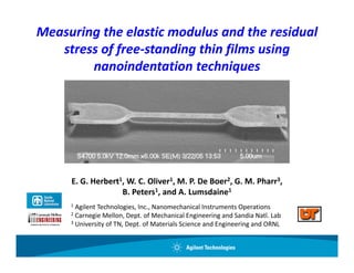
  • 1. Measuring the elastic modulus and the residual  stress of free‐standing thin films using  stress of free‐standing thin films using nanoindentation techniques E. G. Herbert1, W. C. Oliver1, M. P. De Boer2, G. M. Pharr3, B. Peters1, and A. Lumsdaine1 1Agilent Technologies, Inc., Nanomechanical Instruments Operations 2Carnegie Mellon, Dept. of Mechanical Engineering and Sandia Natl. Lab 3U i University of TN, Dept. of Materials Science and Engineering and ORNL it f TN D t f M t i l S i dE i i d ORNL
  • 2. MOTIVATION AND GOALS MEMS:  mechanical characterization forms the basis to quickly and reliably  simulate complex devices and thus avoids the need to incorporate  simulate complex devices and thus avoids the need to incorporate extensive prototyping. Fundamental materials science: controlling the sample geometry and  Fundamental materials science: controlling the sample geometry and dimensions allows enhances our capability to systematically explore  structure‐property relationships linked to microstructure, film thickness,  fabrication, and deposition techniques. fabrication and deposition techniques Among the challenges:  generating reliable data (well understood, robust  experiments that are an accurate reflection of the applied model) and  i t th t t fl ti f th li d d l) d experimental verification. 
  • 3. MOTIVATION AND GOALS What we’re after: • The elastic modulus and the residual stress in free‐standing, metallic thin  films What we set out to accomplish: 1. Simple mathematical model that is easy to implement experimentally • Uniaxial tension stretching not bending tension, stretching not bending 2. Controlling the sample geometry, consistent with assumptions of the model • Dimensional analysis identifies limitations of the model 3. Robust experiment • Stiffness‐displacement, NOT load‐displacement – minimize measurement  errors associated with thermal drift errors associated with thermal drift 4. Experimental verification • Material selection: Aluminum 5wt% copper
  • 4. PROPOSED MODEL l z P F1 F2 P θ θ h w y support post support thin film bridge post P wedge indenter tip Δl 2h ε= = −1 + ⎡ ⎛ 2h ⎞⎤ F P ↑ ∑ Fz = 0 ⇒ F = l σ = = Eε + σ r l sin ⎢tan −1⎜ ⎟⎥ 2 sinθ A ⎝ l ⎠⎦ ⎣ 8 AEh 3 8 Aσ r h 3 4 Aσ r h dP 24 AEh 2 24 Aσ r h 2 4 Aσ r P= − + S= = − + 3 3 3 3 l dh l l l l l
  • 5. THE EFFECT OF THERMAL DRIFT 80 100 mple (μN) Δh = dh/dt (time) 80 60 ΔP = dh/dt (time)(Ksprings) Stiffne (N/m 60 40 Load On Sam ess 40 20 20 m) 0 length = 150 µm 0 width = 22 µm thickness = 0.547 µm -20 -20 0 1000 2000 3000 Displacement (nm)
  • 6. PROPOSED TECHNIQUE ADVANTAGES: MODEL ASSUMPTIONS: • minimizes the effect of thermal minimizes the effect of thermal  • center loading center loading drift • normal, elastic deformation • bending moments may be ignored • improved signal to noise ratio • rigid support posts • model is simple to implement  • the film is flat mathematically DIMENSIONAL ANALYSIS: π 2 ⎛σr ⎞ π 4 ⎛t ⎞ π 2 σr 3π 4 π 4 ⎛t ⎞ 2 2 2 ⎛h⎞ Sl ⎜ ⎟ >> = ⎜⎟+ ⎜⎟+ ⎜⎟ 2 ⎝E⎠ ⎝l⎠ 6 ⎝l ⎠ 6 ⎝l ⎠ AE 8 2E
  • 7. EXPERIMENTAL VERIFICATION • Al 5wt% Cu • dc‐magnetron sputtered at 175 oC • length = 150, 300, and 500 µm • posts are poly Si • width = 22 µm • 50 nm TiN protective coating p g • thickness  0.547 µm thickness = 0.547 µm • wet etchant release with HF • nominal E = 70 GPa • selective wet etch of TiN coating • est. via electrostatic, E = 74.4 GPa ± 2.8,     σ r = 29.9 MPa ± 0.3 = 
  • 8. STIFFNESS‐DISPLACEMENT RESPONSE 40 frequency = 20 Hz 35 Loading osc. amp. = 30 nm Unloading length = 150 µm 30 tiffness (N/m) width = 22 µm 25 thickness = 0.571 µm strain = 0.04% 20 15 estimated by electrostatic estimated by electrostatic St 10 techniques: E = 74.4 GPa ± 3.8% 5 σ r = 29.9 MPa ± 1% 0 -400 0 400 800 1200 1600 2000 Displacement (nm)
  • 9. STIFFNESS‐DISPLACEMENT RESPONSE 40 frequency = 20 Hz 35 Loading osc. amp. = 30 nm Unloading length = 150 µm 30 tiffness (N/m) width = 22 µm 25 thickness = 0.571 µm Misalignment, strain = 0.04% 20 1.6o 15 estimated by electrostatic estimated by electrostatic St 10 techniques: peak‐to‐peak =   E = 74.4 GPa ± 3.8% 5 σ r = 29.9 MPa ± 1% 2 2 ( rms ) = 85 nm 0 -400 0 400 800 1200 1600 2000 Displacement (nm)
  • 10. STIFFNESS‐DISPLACEMENT RESPONSE 40 frequency = 20 Hz E = 75.3 GPa +/- 1% 35 osc. amp. = 30 nm σr = 28.7 MPa +/ 0 6% 28 7 +/- 0.6% length = 150 µm tiffness (N/m) 30 width = 22 µm thickness = 0.571 µm 25 strain = 0.04% 20 2 y = 9.628 + 6.662E+12x R = 0.9992 estimated by electrostatic estimated by electrostatic 15 St 2 techniques: y = 9.631 + 6.685E+12x R = 0.9992 E = 74.4 GPa ± 3.8% 2 y = 9.651 + 6.74E+12x R = 0.9995 10 σ r = 29.9 MPa ± 1% 2 y = 9.514 + 6.809E+12x R = 0.9994 5 1x10-12 2x10-12 3x10-12 4x10-12 5x10-12 0 Displacement2 (m2) p (
  • 11. STIFFNESS‐DISPLACEMENT RESPONSE 80 length = 150 μm 70 disp. = 3 μm, 3x osc. amp. = 40 nm 60 Stiffness (N/m) length = 300 μm frequency = 45 Hz 50 disp. = 6 μm, 2x width = 22 µm width = 22 µm s osc. amp. = 60 nm 40 thickness = 0.547 µm 30 strain = 0.08% length = 500 μm disp. = 10 μm, 3 S di 3x 20 osc. amp. = 120 nm 10 0 1.5x10⁻¹¹ 3x10-11 4.5x10⁻¹¹ 6x10-11 0 Displacement2 (m2)
  • 12. EXPERIMENTAL VERIFICATION GPa) 80 40 Re sticity (G 70 esidual Stress (MPa) As expected, the modulus  is independent of length  60 30 and bending behavior  50 Modulus of Elas Residual stress, on the  other hand, is effected by: 40 20 1.  CTE = 23x10‐6/K E, proposed technique ΔT = 3 oC 30 E, electrostatic technique σ = 5.2 MPa σr , proposed technique 20 2.  Bending behavior 10 σr , electrostatic technique 10 0 0 100 200 300 400 500 Bridge Length (μm) g g (μ )
  • 13.
  • 14.
  • 15.
  • 16.
  • 17. CLOSING REMARKS • We have proposed a simple model to measure the elastic modulus and residual  stress of free‐standing metallic thin films ~ Based on the relationship between stiffness and displacement because it Based on the relationship between stiffness and displacement because it  minimizes the effects of thermal drift ~ Model assumes normal, elastic deformation of a flat film that does not support  bending moments and is rigidly mounted – the model is simple to implement  bd d dl dh dl l l mathematically and dimensional analysis identifies the appropriate limits • Experimental verification of the proposed technique was provided by measuring  the elastic modulus and residual stress of four Al/5wt% Cu free‐standing films ~ E matches within 2% of the result obtained by electrostatic actuation,  independent of the observed bending independent of the observed bending ~ σ r matches within 19.1% of the result obtained by electrostatic actuation,  discrepancy attributed to the CTE (ΔT = 3oC) and/or bending behavior – dimensional analysis predicted the overestimation