Abrasive Jet Mechaning (Modern Manufacturing Process
•
0 likes•20 views

STUDY OF ABRASIVE JET MACHINING PROCESS

Recommended
Recommended
More Related Content
What's hot
What's hot (20)
Similar to Abrasive Jet Mechaning (Modern Manufacturing Process
Similar to Abrasive Jet Mechaning (Modern Manufacturing Process (20)
More from Dinesh Panchal
More from Dinesh Panchal (13)
Recently uploaded
Recently uploaded (20)
Abrasive Jet Mechaning (Modern Manufacturing Process
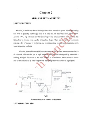
- 1. 11 Chapter 2 ABRASIVE JET MACHINING 2.1 INTRODUCTION Abrasive jet and Water Jet technologies have been around for years. Water jet cutting has been a specialty technology used in a large no. of industries since about 1970. Around 1993, big advances in the technology were introduced that have caused this technology to become very popular for machine shops. There are now a lot of companies making a lot of money by replacing and complementing conventional machining with water jet cutting methods. Abrasive jet machining (AJM) uses a stream of fine grained abrasives mixed with air or some other carrier gas at high pressure. This stream is designed by means of a suitably designed nozzle on to the work surface to be machined. Metal removal occurs due to erosion caused by abrasive particles impacting the work surface at high speed. Fig.2.1 Schematic diagram of Abrasive Jet Machining 2.2 VARIABLES IN AJM
- 2. 12 The variables that influence the Metal Removal Rate (MRR) & accuracy of machining in this process are discussed here as follows: 1. Carrier Gas 2. Type of Abrasive used 3. Size of Abrasive Grain 4. Jet Velocity 5. Work Material 6. Stand Off Distance (SOD) 7. Nozzle Design 8. Shape of Cut 9. Mean number of Abrasive Grains per unit volume of carrier gas. These variables are being discussed in detail as follows. 2.2.1 CARRIER GAS The carrier gas to be used in AJM must not flare excessively when discharged from nozzle into the atmosphere. Further, the gas should be non toxic, cheap easily available & capable of being dried and cleaned without difficulty. The gases that can be used are air, carbon dioxide or nitrogen. Air is most widely used owing to easy availability & little cost. All abrasive powders supplied by manufacturers can be run with clean shop air, provided air filters have been installed in the air lines. 2.2.2 TYPE OF ABRASIVES The choice of abrasive depends on the type of machining operations, for example, roughing, finishing etc., work material & cost. The abrasive should have a sharp & irregular shape & be fine enough to remain suspended in the carrier gas & should have excellent flow characteristics. The abrasives used for cutting are aluminum oxide & silicon carbide, whereas sodium bicarbonate, dolomite, glass beads, etc., are used for cleaning, etching, deburring & polishing. Re use of abrasives is not recommended
- 3. 13 because not only its cutting ability decrease, but contamination also clogs the orifice of nozzle. 2.2.3 GRAIN SIZE The rate of metal removal depends on the size of abrasive grains. Finer grains are less irregular in shape, & hence posses less cutting ability. Moreover, finer grains tend to stick together & clog the nozzle. The most favorable grain sizes ranges from 10 to 50 micrometers. Coarse grains are recommended for cutting, whereas finer grains are useful in polishing, deburrings, etc. 2.2.4 JET VELOCITY The kinetic energy of abrasive jet is utilized for metal removal by erosion. Finnie & Sheldon have shown that for the erosion to occur, the jet must impinge the work surface with certain minimum velocity. For erosion of gas by silicon carbide (grain size 25 micrometer), the minimum jet velocity has been found to be 150m/s.The jet velocity is a function of nozzle pressure, nozzle design, abrasive grain size & mean number of abrasives per unit volume of carrier gas. Fig.2.2 Fig.2.3 Effect of abrasive jet pressure on material Effect of material removal rate.
- 4. 14 Abrasive: Aluminum oxide, rate. Abrasive: aluminum Work Material: Glass. Oxide. Work material; cemented carbide. 2.2.5 WORK MATERIAL AJM is recommended for processing of brittle materials, such as glass, ceramics, refractories, etc. Most of ductile materials are practically unmachinable by AJM. The rate of metal removal has been found to be depending on Mohr’s hardness of the material to be machined. 2.2.6 STAND OFF DISTANCE (SOD) Stand off is defined as distance between the face of the nozzle & the working surface at work. SOD has been found to have considerable effect on the rate of metal removal as well as accuracy. A large SOD results in the flaring of jet which results in poor accuracy. Small metal removal rates at a low SOD is due to a large reduction nozzle pressure with decreasing distance, whereas a drop in metal removal rate at large SOD is due to a reduction in the jet velocity with increasing distance.
- 5. 15 Fig.2.4 Effect of Stand off Distance on the accuracy of shape produced Fig.2.5 Effect of stand off distance on material removal rate
- 6. 16 2.2.7 NOZZLE DESIGN The nozzle has to with stand the erosive action of abrasive particles, & hence, must be made of materials that can provide high resistance to wear. The common materials for nozzle are sapphire & tungsten carbide. The nozzles should be so esigned that pressure loss due to bends, friction etc. is as little as possible. Depending on the requirements, the nozzles may be either circular or rectangular cross sections. 2.2.8 SHAPE OF CUT The accuracy of machining is also dependent upon the shape of cut. It may not be possible to machine components with sharp corners because of stray cutting in this process. 2.2.9 EAN NUMBER OF ABRASIVE GRAINS PER UNIT VOLUME OF THE CARRIER GAS An idea about the mean no of abrasive grains per unit volume of the carrier gas can be obtained from the mixing ratio M. It is defined as follows: M = Volume flow rate of abrasive per unit time Volume flow rate of carrier gas per unit time A large value of M should result in higher rates of metal removal but a large abrasive flow rate has been found to adversely influence jet velocity, & may sometimes even clog the nozzle. Thus, for given conditions, there is an optimum mixing ratio that leads to a maximum metal removal rate. 2.3 APPLICATIONS
- 7. 17 Lavoie & Inguilli have both mentioned number of interesting applications of AJM. This process has been successfully applied for the following applications: 1. Removing flash & parting lines from injection molded parts. 2. Deburring & polishing plastic, nylon & Teflon components. 3. Cleaning metallic mould cavities which otherwise may be inaccessible. 4. Cutting thin section fragile components made of glass, refractories, ceramics, mica, etc. 5. Producing high quality surface. 6. Removing glue & paint from paintings & leather objects. 7. Reproducing designs on glass surface with help of masks made of rubber, copper, etc. 8. Frosting interior surfaces of glass tubes. 9. Etching markings on glass cylinders. 2.4 METAL REMOVAL RATE IN AJM Taking in to consideration the fact that metal removal is due to chipping of the work surface brought about by impacting the abrasive particles. Sarkar & Pandey proposed a mathematical model for the computation of metal removal rate in AJM. They have shown that rate of metal removal Q in AJM can be obtained by: Q = kNd^3. v ^3/2 ( ρ) ^3/4 12H Where Q = MRR in AJM K = constant N = no of abrasive particles impacting per unit time d = mean diameter of abrasive particles v = jet velocity ρ = density of abrasive particles
- 8. 18 H = hardness of work material 2.5 ADVANTAGES 1. The advantage of this process lies in its ability to machine brittle materials with thin sections especially in areas which are inaccessible by ordinary methods. 2. Absence of tool work contact & metal removal at microscopic scale leads to very little or no heat generation, resulting in insignificant surface damage. 3. The process is characterized by low capital investment & low power consumption 2.6 DISADVANTAGES 1. The ductile materials are practically unmachinable by AJM because of low MRR. 2. Sometimes the parts machined by this process have to undergo an additional operation of cleaning as there is a possibility of abrasive grains sticking to the surface. 3. The machining accuracy is poor. 4. The nozzle wear rate is high. 5. The process is not environment friendly.