SlideShare a Scribd company logo
1 of 1
Download to read offline
Analogue and Digital Systems


                                           Analogue systems

Analogue systems process analogue signals which can take any value within a range, for example the
output from an LDR (light sensor) or a microphone.
An audio amplifier is an example of an analogue system. The amplifier produces an output voltage which
                                                                                                            Analogue signal
can be any value within the range of its power supply.
An analogue meter can display any value within the range available on its scale. However, the precision
of readings is limited by our ability to read them. For example the meter on the right shows 1.25V
because the pointer is estimated to be half way between 1.2 and 1.3. The analogue meter can show any
value between 1.2 and 1.3 but we are unable to read the scale more precisely than about half a division. Analogue meter display
All electronic circuits suffer from 'noise' which is unwanted signal mixed in with the desired signal, for
example an audio amplifier may pick up some mains 'hum' (the 50Hz frequency of the UK mains electricity supply). Noise can be
difficult to eliminate from analogue signals because it may be hard to distinguish from the desired signal.

                                            Digital systems

Digital systems process digital signals which can take only a limited number of values (discrete steps),
usually just two values are used: the positive supply voltage (+Vs) and zero volts (0V).
Digital systems contain devices such as logic gates, flip-flops, shift registers and counters. A computer is
                                                                                                                   Digital (logic) signal
an example of a digital system.
A digital meter can display many values, but not every value within its range. For example the display on
the right can show 6.25 and 6.26 but not a value between them. This is not a problem because digital
meters normally have sufficient digits to show values more precisely than it is possible to read an
analogue display.                                                                                                  Digital meter display
                                              Logic signals
Most digital systems use the simplest possible type of signal which has just two values. This type of signal is
called a logic signal because the two values (or states) can be called true and false. Normally the positive
                                                                                                                         Logic states
supply voltage +Vs represents true and 0V represents false. Other labels for the true and false states are shown          True False
in the table on the right.
                                                                                                                             1        0
 Noise is relatively easy to eliminate from digital signals because it is easy to distinguish from the desired signal     High      Low
which can only have particular values. For example: if the signal is meant to be +5V (true) or 0V (false), noise of
up to 2.5V can be eliminated by treating all voltages greater than 2.5V as true and all voltages less than 2.5V as         +Vs       0V
                                                         false.
                                                                                                                           On        Off


                                                 Internet Backup information:

        Electronics Club Home Page                                              Frequently Asked Questions
        Site Map                                                                Links to other Electronics sites
        Example Projects
        Construction of Projects
        Soldering Guide
        Study Electronics                                                                    www.kpsec.freeuk.com
        Electronic Components
        Circuit Symbols

More Related Content

What's hot

Cdi t1 10_gen_unit3_revision_notes_eot
Cdi t1 10_gen_unit3_revision_notes_eotCdi t1 10_gen_unit3_revision_notes_eot
Cdi t1 10_gen_unit3_revision_notes_eotCDI Aljeer
 
Digital Electronics Notes
Digital Electronics Notes Digital Electronics Notes
Digital Electronics Notes Srikrishna Thota
 
The IoT Academy IoT training Arduino Part 4 Arduino interfaces
The IoT Academy IoT training Arduino Part 4 Arduino interfacesThe IoT Academy IoT training Arduino Part 4 Arduino interfaces
The IoT Academy IoT training Arduino Part 4 Arduino interfacesThe IOT Academy
 
Digital electronics nandhini kusuma
Digital electronics nandhini kusumaDigital electronics nandhini kusuma
Digital electronics nandhini kusumakusuma11
 
The fundemental of electronics ebook
The fundemental of electronics ebookThe fundemental of electronics ebook
The fundemental of electronics ebookLe Thanh Nhan
 
To measure the intensity of light using LDR sensor by calibrating voltage wit...
To measure the intensity of light using LDR sensor by calibrating voltage wit...To measure the intensity of light using LDR sensor by calibrating voltage wit...
To measure the intensity of light using LDR sensor by calibrating voltage wit...Ankita Tiwari
 
Lec1 - Analog and Digital systems
Lec1 - Analog and Digital systemsLec1 - Analog and Digital systems
Lec1 - Analog and Digital systemsMuhammad Salman
 
diccionary
diccionarydiccionary
diccionarymaxi1854
 
Analogue to digital conversion
Analogue to digital conversionAnalogue to digital conversion
Analogue to digital conversionsimonandisa
 
Free Electronics Projects Circuits and their Applications
Free Electronics Projects Circuits and their ApplicationsFree Electronics Projects Circuits and their Applications
Free Electronics Projects Circuits and their ApplicationsElectronics Hub
 
Electronics Project Book
Electronics Project BookElectronics Project Book
Electronics Project BookVarun Bansal
 

What's hot (16)

Cdi t1 10_gen_unit3_revision_notes_eot
Cdi t1 10_gen_unit3_revision_notes_eotCdi t1 10_gen_unit3_revision_notes_eot
Cdi t1 10_gen_unit3_revision_notes_eot
 
Analog vs digital
Analog vs digitalAnalog vs digital
Analog vs digital
 
Digital Electronics Notes
Digital Electronics Notes Digital Electronics Notes
Digital Electronics Notes
 
The IoT Academy IoT training Arduino Part 4 Arduino interfaces
The IoT Academy IoT training Arduino Part 4 Arduino interfacesThe IoT Academy IoT training Arduino Part 4 Arduino interfaces
The IoT Academy IoT training Arduino Part 4 Arduino interfaces
 
Digital electronics nandhini kusuma
Digital electronics nandhini kusumaDigital electronics nandhini kusuma
Digital electronics nandhini kusuma
 
The fundemental of electronics ebook
The fundemental of electronics ebookThe fundemental of electronics ebook
The fundemental of electronics ebook
 
To measure the intensity of light using LDR sensor by calibrating voltage wit...
To measure the intensity of light using LDR sensor by calibrating voltage wit...To measure the intensity of light using LDR sensor by calibrating voltage wit...
To measure the intensity of light using LDR sensor by calibrating voltage wit...
 
Lec1 - Analog and Digital systems
Lec1 - Analog and Digital systemsLec1 - Analog and Digital systems
Lec1 - Analog and Digital systems
 
Open Power Monitor
Open Power Monitor Open Power Monitor
Open Power Monitor
 
diccionary
diccionarydiccionary
diccionary
 
Analogue to digital conversion
Analogue to digital conversionAnalogue to digital conversion
Analogue to digital conversion
 
Free Electronics Projects Circuits and their Applications
Free Electronics Projects Circuits and their ApplicationsFree Electronics Projects Circuits and their Applications
Free Electronics Projects Circuits and their Applications
 
Electronics Project Book
Electronics Project BookElectronics Project Book
Electronics Project Book
 
Embedded unit ii
Embedded unit iiEmbedded unit ii
Embedded unit ii
 
Hasna
HasnaHasna
Hasna
 
6.4.3comparison2
6.4.3comparison26.4.3comparison2
6.4.3comparison2
 

Viewers also liked

¿Y DÓNDE LEEMOS?.
¿Y DÓNDE LEEMOS?. ¿Y DÓNDE LEEMOS?.
¿Y DÓNDE LEEMOS?. Marco Javes
 
555 and 556 timer circuits
555 and 556 timer circuits555 and 556 timer circuits
555 and 556 timer circuitsEdmund Merren
 
Ac, dc and electrical signals
Ac, dc and electrical signalsAc, dc and electrical signals
Ac, dc and electrical signalsEdmund Merren
 
Evaluacion alternativas
Evaluacion alternativasEvaluacion alternativas
Evaluacion alternativasleoalreves
 
Txartela GEHIAGO GUTXIAGO 4 ERAGIKETAK
Txartela  GEHIAGO GUTXIAGO  4 ERAGIKETAK Txartela  GEHIAGO GUTXIAGO  4 ERAGIKETAK
Txartela GEHIAGO GUTXIAGO 4 ERAGIKETAK idoialariz
 

Viewers also liked (8)

¿Y DÓNDE LEEMOS?.
¿Y DÓNDE LEEMOS?. ¿Y DÓNDE LEEMOS?.
¿Y DÓNDE LEEMOS?.
 
3000 w inverter
3000 w inverter 3000 w inverter
3000 w inverter
 
3 dslideshare
3 dslideshare3 dslideshare
3 dslideshare
 
555 and 556 timer circuits
555 and 556 timer circuits555 and 556 timer circuits
555 and 556 timer circuits
 
Ac, dc and electrical signals
Ac, dc and electrical signalsAc, dc and electrical signals
Ac, dc and electrical signals
 
Ds group
Ds groupDs group
Ds group
 
Evaluacion alternativas
Evaluacion alternativasEvaluacion alternativas
Evaluacion alternativas
 
Txartela GEHIAGO GUTXIAGO 4 ERAGIKETAK
Txartela  GEHIAGO GUTXIAGO  4 ERAGIKETAK Txartela  GEHIAGO GUTXIAGO  4 ERAGIKETAK
Txartela GEHIAGO GUTXIAGO 4 ERAGIKETAK
 

Similar to Analogue and digital systems

ICS 2205 Chapter 1 - Introduction.pptx
ICS 2205 Chapter 1 - Introduction.pptxICS 2205 Chapter 1 - Introduction.pptx
ICS 2205 Chapter 1 - Introduction.pptxssuser71a3af
 
Cs302 shortnoteslectures1to45
Cs302 shortnoteslectures1to45Cs302 shortnoteslectures1to45
Cs302 shortnoteslectures1to45javediqbalmirza
 
3110016_BE_GTU_Study_Material_e-Notes_6_02052020063009AM.pdf
3110016_BE_GTU_Study_Material_e-Notes_6_02052020063009AM.pdf3110016_BE_GTU_Study_Material_e-Notes_6_02052020063009AM.pdf
3110016_BE_GTU_Study_Material_e-Notes_6_02052020063009AM.pdfVirangPatel15
 
Digital Signal Conditioning
Digital Signal ConditioningDigital Signal Conditioning
Digital Signal ConditioningGhansyam Rathod
 
18cs33_module_1.pptx
18cs33_module_1.pptx18cs33_module_1.pptx
18cs33_module_1.pptxTLRTHR
 
Degital 1
Degital 1Degital 1
Degital 1hnaita
 
Data acquisition system
Data acquisition systemData acquisition system
Data acquisition systemgirishgandhi4
 
Digital Electronics Notes
Digital Electronics NotesDigital Electronics Notes
Digital Electronics NotesMathankumar S
 
How to Build a Digital Weighing Scale
How to Build a Digital Weighing ScaleHow to Build a Digital Weighing Scale
How to Build a Digital Weighing ScaleTacuna Systems
 
Programming
ProgrammingProgramming
Programmingaescotom
 
Programming
ProgrammingProgramming
Programmingaescotom
 
Concept of Digital measurement, block Diagram & study of Voltmeter
Concept of Digital measurement, block Diagram & study of VoltmeterConcept of Digital measurement, block Diagram & study of Voltmeter
Concept of Digital measurement, block Diagram & study of VoltmeterAbhishek Choksi
 
Unit IV DA & AD Convertors and Phase Locked Loop
Unit IV  DA & AD Convertors and Phase Locked LoopUnit IV  DA & AD Convertors and Phase Locked Loop
Unit IV DA & AD Convertors and Phase Locked LoopDr.Raja R
 
Design of Speed Optimized Analog to Digital Converter using VHDL
Design of Speed Optimized Analog to Digital Converter using VHDLDesign of Speed Optimized Analog to Digital Converter using VHDL
Design of Speed Optimized Analog to Digital Converter using VHDLIOSR Journals
 
The iot academy_embeddedsystems_training_basicselectronicspart2
The iot academy_embeddedsystems_training_basicselectronicspart2The iot academy_embeddedsystems_training_basicselectronicspart2
The iot academy_embeddedsystems_training_basicselectronicspart2The IOT Academy
 

Similar to Analogue and digital systems (20)

ICS 2205 Chapter 1 - Introduction.pptx
ICS 2205 Chapter 1 - Introduction.pptxICS 2205 Chapter 1 - Introduction.pptx
ICS 2205 Chapter 1 - Introduction.pptx
 
ADC & DAC
ADC & DACADC & DAC
ADC & DAC
 
Cs302 shortnoteslectures1to45
Cs302 shortnoteslectures1to45Cs302 shortnoteslectures1to45
Cs302 shortnoteslectures1to45
 
3110016_BE_GTU_Study_Material_e-Notes_6_02052020063009AM.pdf
3110016_BE_GTU_Study_Material_e-Notes_6_02052020063009AM.pdf3110016_BE_GTU_Study_Material_e-Notes_6_02052020063009AM.pdf
3110016_BE_GTU_Study_Material_e-Notes_6_02052020063009AM.pdf
 
Digital Signal Conditioning
Digital Signal ConditioningDigital Signal Conditioning
Digital Signal Conditioning
 
18cs33_module_1.pptx
18cs33_module_1.pptx18cs33_module_1.pptx
18cs33_module_1.pptx
 
Assiment
AssimentAssiment
Assiment
 
Degital 1
Degital 1Degital 1
Degital 1
 
Data acquisition system
Data acquisition systemData acquisition system
Data acquisition system
 
Digital voltmeter project
Digital voltmeter projectDigital voltmeter project
Digital voltmeter project
 
Digital Electronics Notes
Digital Electronics NotesDigital Electronics Notes
Digital Electronics Notes
 
How to Build a Digital Weighing Scale
How to Build a Digital Weighing ScaleHow to Build a Digital Weighing Scale
How to Build a Digital Weighing Scale
 
Programming
ProgrammingProgramming
Programming
 
Programming
ProgrammingProgramming
Programming
 
Arduino Programming.pdf
Arduino Programming.pdfArduino Programming.pdf
Arduino Programming.pdf
 
Concept of Digital measurement, block Diagram & study of Voltmeter
Concept of Digital measurement, block Diagram & study of VoltmeterConcept of Digital measurement, block Diagram & study of Voltmeter
Concept of Digital measurement, block Diagram & study of Voltmeter
 
Unit IV DA & AD Convertors and Phase Locked Loop
Unit IV  DA & AD Convertors and Phase Locked LoopUnit IV  DA & AD Convertors and Phase Locked Loop
Unit IV DA & AD Convertors and Phase Locked Loop
 
Class 12th Logic Gates
Class 12th Logic GatesClass 12th Logic Gates
Class 12th Logic Gates
 
Design of Speed Optimized Analog to Digital Converter using VHDL
Design of Speed Optimized Analog to Digital Converter using VHDLDesign of Speed Optimized Analog to Digital Converter using VHDL
Design of Speed Optimized Analog to Digital Converter using VHDL
 
The iot academy_embeddedsystems_training_basicselectronicspart2
The iot academy_embeddedsystems_training_basicselectronicspart2The iot academy_embeddedsystems_training_basicselectronicspart2
The iot academy_embeddedsystems_training_basicselectronicspart2
 

Analogue and digital systems

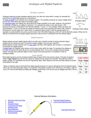
  • 1. Analogue and Digital Systems Analogue systems Analogue systems process analogue signals which can take any value within a range, for example the output from an LDR (light sensor) or a microphone. An audio amplifier is an example of an analogue system. The amplifier produces an output voltage which Analogue signal can be any value within the range of its power supply. An analogue meter can display any value within the range available on its scale. However, the precision of readings is limited by our ability to read them. For example the meter on the right shows 1.25V because the pointer is estimated to be half way between 1.2 and 1.3. The analogue meter can show any value between 1.2 and 1.3 but we are unable to read the scale more precisely than about half a division. Analogue meter display All electronic circuits suffer from 'noise' which is unwanted signal mixed in with the desired signal, for example an audio amplifier may pick up some mains 'hum' (the 50Hz frequency of the UK mains electricity supply). Noise can be difficult to eliminate from analogue signals because it may be hard to distinguish from the desired signal. Digital systems Digital systems process digital signals which can take only a limited number of values (discrete steps), usually just two values are used: the positive supply voltage (+Vs) and zero volts (0V). Digital systems contain devices such as logic gates, flip-flops, shift registers and counters. A computer is Digital (logic) signal an example of a digital system. A digital meter can display many values, but not every value within its range. For example the display on the right can show 6.25 and 6.26 but not a value between them. This is not a problem because digital meters normally have sufficient digits to show values more precisely than it is possible to read an analogue display. Digital meter display Logic signals Most digital systems use the simplest possible type of signal which has just two values. This type of signal is called a logic signal because the two values (or states) can be called true and false. Normally the positive Logic states supply voltage +Vs represents true and 0V represents false. Other labels for the true and false states are shown True False in the table on the right. 1 0 Noise is relatively easy to eliminate from digital signals because it is easy to distinguish from the desired signal High Low which can only have particular values. For example: if the signal is meant to be +5V (true) or 0V (false), noise of up to 2.5V can be eliminated by treating all voltages greater than 2.5V as true and all voltages less than 2.5V as +Vs 0V false. On Off Internet Backup information: Electronics Club Home Page Frequently Asked Questions Site Map Links to other Electronics sites Example Projects Construction of Projects Soldering Guide Study Electronics www.kpsec.freeuk.com Electronic Components Circuit Symbols