1. 1 (c) 2012 Z-Wave Europe GmbH, Goldbachstr. 13, 09337 Hohenstein-Ernstthal, Germany, www.zwaveeurope.com
DUW_054313
Wall Switch Set for Design Duwi Everlux
Firmware Version : 1.0
Quick Start
A This device is a Z-Wave actuator. Triple click one of the buttons on the device will include the device. A green blinking of LED
will indicate successful inclusion. The device is excluded by triple click to one of the buttons.
Please refer to the chapters below for detailed information about all aspects of the products usage.
Product description
The Duwi Switch Flush Mountable is a wireless actuator able to switch loads up to 2300 W. The device is delivered as a complete
set with flush mountable insert, paddle and mounting frame compatible to the design of the switching series Duwi Everlux white.
The paddle of the device is used to control the device itself . The status of the switch is indicated on a dual color LED for test
purposes. This device is designed for a 3 wire system and needs a neutral wire in the wall box.
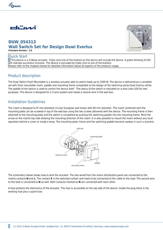
Installation Guidelines
The insert is designed to fit into standard circular European wall boxes with 60 mm diameter. The insert combined with the
mounting plate can be screwed in top of the wall box using the two screws delivered with the device. The mounting frame is then
attached to the mounting plate and the switch is completed by pushing the switching paddle into the mounting frame. Mind the
arrow on the inserts top side showing the mounting direction of the insert. It is also possible to mount the insert without any local
operation behind a cover or inside a lamp. The mounting plate, frame and the switching paddle become useless in such a scenario.
The schematics below shows how to wire the actuator. The two wired from the mains distribution panel are connected to the
inserts contacts N and L. The contact S is the switched contact and need to be connected to the cable to the load. The second wire
to the load is connected to N as well. Both contacts marked as N are connected with each other.
A fuse protects the electronics of the actuator. The fuse is accessible on the top side of the device. Inside the plug there is the
working fuse plus a spare fuse.
2. 2 (c) 2012 Z-Wave Europe GmbH, Goldbachstr. 13, 09337 Hohenstein-Ernstthal, Germany, www.zwaveeurope.com
Behavior within the Z-Wave network
I On factory default the device does not belong to any Z-Wave network. The device needs to join an existing wireless network to
communicate with the devices of this network. This process is called Inclusion. Devices can also leave a network. This process is
called Exclusion. Both processes are initiated by the primary controller of the Z-Wave network. This controller will be turned into
exclusion respective inclusion mode. Please refer to your primary controllers manual on how to turn your controller into inclusion
or exclusion mode. Only if the primary controller is in inclusion or exclusion mode, this device can join or leave the network.
Leaving the network - i.e. being excluded - sets the device back to factory default.
If the device already belongs to a network, follow the exclusion process before including it in your network. Otherwise inclusion of
this device will fail. If the controller being included was a primary controller, it has to be reset first.
Blinking red/green LED indicates that the device is in factory reset state. Once the controller is turned into inclusion mode triple
click one of the buttons on the device will include the device. A green blinking of LED will indicate successful inclusion that
will be turned off shortly afterwards. The device is excluded by triple click to one of the buttons when the controller is in
exclusion mode.
Operating the device
The actuator is operated by the local switching paddles or wirelessly using Z-Wave commands (communication patterns 1, 4, 5 and
7). If the insert is mounted correctly pushing the upper part of the paddle will turn on the load; pushing the lower part of the
paddle will turn off the electric load.
The device is also able to remotely operate other devices (communication pattern 5) by sending wireless Z-Wave commands. In
case the remote device is a switch as well the remote operation is similar to the local operation by pushing upper to lower part of
the switching paddle.
Child Protection
The device can be turn into a child protection mode. In this mode all local operation is disabled.
The child protection mode MUST be turned on wirelessly. However in protected by sequence mode it is possible to unlock the
device for local operation with a triple click. The unlock state will last for 5 seconds.
LED Control
Red and green blinking continuously: Device is not included in a Z-Wave networkq
3. 3 (c) 2012 Z-Wave Europe GmbH, Goldbachstr. 13, 09337 Hohenstein-Ernstthal, Germany, www.zwaveeurope.com
Red lights up for 3 seconds: Device was not included/excluded after being put into learn mode by triple press of up/down buttonq
Green lights up for 3 seconds: The inclusion/exclusion was successful or new association was saved successfullyq
Green or no light: depending on settings of configuration parameter for LED controlq
Associations
A Z-Wave devices control other Z-Wave devices. The relationship between one device controlling another device is called
association. In order to control a different device, the controlling device needs to maintain a list of devices that will receive
controlling commands. These lists are called association groups and they are always related to certain events (e.g. button
pressed, sensor triggers, ...). In case the event happens all devices stored in the respective association group will receive a
common wireless command.
Association Groups:
1 Basic On/Off Group (max. nodes in group: 5)
Technical Data
Power Supply 230V ~50-60 Hz
Attachable Loads up to 2300 W resistive load or up to 460 VA inductive load
Fuse Type: T 1.25 A H (Load 1.25 Ampere, high shutdown capacity), D: 5 mm, L: 20 mm
IP Rating IP 20
Frequency 868.42 MHz (SRD Band)
Wireless Range up to 100 m outside, on average up to 20 m inside buildings
Explorer Frame Support No
SDK 5.02 pl2
Device Type Slave with routing capabilities
Generic Device Class Binary Switch
Specific Device Class Binary Power Switch
Routing Yes
FLiRS No
Firmware Version 1.0